CN1553821A - Methods and devices for using percutaneous probes - Google Patents
Methods and devices for using percutaneous probes Download PDFInfo
- Publication number
- CN1553821A CN1553821A CNA028178491A CN02817849A CN1553821A CN 1553821 A CN1553821 A CN 1553821A CN A028178491 A CNA028178491 A CN A028178491A CN 02817849 A CN02817849 A CN 02817849A CN 1553821 A CN1553821 A CN 1553821A
- Authority
- CN
- China
- Prior art keywords
- housing
- skin surface
- electrode
- equipment
- receptor
- Prior art date
- Legal status (The legal status is an assumption and is not a legal conclusion. Google has not performed a legal analysis and makes no representation as to the accuracy of the status listed.)
- Granted
Links
Images


Classifications
-
- A—HUMAN NECESSITIES
- A61—MEDICAL OR VETERINARY SCIENCE; HYGIENE
- A61N—ELECTROTHERAPY; MAGNETOTHERAPY; RADIATION THERAPY; ULTRASOUND THERAPY
- A61N1/00—Electrotherapy; Circuits therefor
- A61N1/02—Details
- A61N1/04—Electrodes
-
- A—HUMAN NECESSITIES
- A61—MEDICAL OR VETERINARY SCIENCE; HYGIENE
- A61N—ELECTROTHERAPY; MAGNETOTHERAPY; RADIATION THERAPY; ULTRASOUND THERAPY
- A61N1/00—Electrotherapy; Circuits therefor
- A61N1/02—Details
- A61N1/04—Electrodes
- A61N1/05—Electrodes for implantation or insertion into the body, e.g. heart electrode
- A61N1/0502—Skin piercing electrodes
-
- A—HUMAN NECESSITIES
- A61—MEDICAL OR VETERINARY SCIENCE; HYGIENE
- A61N—ELECTROTHERAPY; MAGNETOTHERAPY; RADIATION THERAPY; ULTRASOUND THERAPY
- A61N1/00—Electrotherapy; Circuits therefor
-
- A—HUMAN NECESSITIES
- A61—MEDICAL OR VETERINARY SCIENCE; HYGIENE
- A61N—ELECTROTHERAPY; MAGNETOTHERAPY; RADIATION THERAPY; ULTRASOUND THERAPY
- A61N1/00—Electrotherapy; Circuits therefor
- A61N1/02—Details
- A61N1/04—Electrodes
- A61N1/05—Electrodes for implantation or insertion into the body, e.g. heart electrode
- A61N1/0551—Spinal or peripheral nerve electrodes
-
- A—HUMAN NECESSITIES
- A61—MEDICAL OR VETERINARY SCIENCE; HYGIENE
- A61N—ELECTROTHERAPY; MAGNETOTHERAPY; RADIATION THERAPY; ULTRASOUND THERAPY
- A61N1/00—Electrotherapy; Circuits therefor
- A61N1/18—Applying electric currents by contact electrodes
- A61N1/32—Applying electric currents by contact electrodes alternating or intermittent currents
- A61N1/36—Applying electric currents by contact electrodes alternating or intermittent currents for stimulation
- A61N1/36014—External stimulators, e.g. with patch electrodes
- A61N1/36021—External stimulators, e.g. with patch electrodes for treatment of pain
-
- A—HUMAN NECESSITIES
- A61—MEDICAL OR VETERINARY SCIENCE; HYGIENE
- A61N—ELECTROTHERAPY; MAGNETOTHERAPY; RADIATION THERAPY; ULTRASOUND THERAPY
- A61N1/00—Electrotherapy; Circuits therefor
- A61N1/18—Applying electric currents by contact electrodes
- A61N1/32—Applying electric currents by contact electrodes alternating or intermittent currents
- A61N1/36—Applying electric currents by contact electrodes alternating or intermittent currents for stimulation
- A61N1/36014—External stimulators, e.g. with patch electrodes
- A61N1/36017—External stimulators, e.g. with patch electrodes with leads or electrodes penetrating the skin
Landscapes
- Health & Medical Sciences (AREA)
- Life Sciences & Earth Sciences (AREA)
- General Health & Medical Sciences (AREA)
- Public Health (AREA)
- Animal Behavior & Ethology (AREA)
- Veterinary Medicine (AREA)
- Engineering & Computer Science (AREA)
- Biomedical Technology (AREA)
- Nuclear Medicine, Radiotherapy & Molecular Imaging (AREA)
- Radiology & Medical Imaging (AREA)
- Heart & Thoracic Surgery (AREA)
- Cardiology (AREA)
- Biophysics (AREA)
- Neurology (AREA)
- Orthopedic Medicine & Surgery (AREA)
- Neurosurgery (AREA)
- Pain & Pain Management (AREA)
- Electrotherapy Devices (AREA)
- Media Introduction/Drainage Providing Device (AREA)
- Finger-Pressure Massage (AREA)
- Measuring Pulse, Heart Rate, Blood Pressure Or Blood Flow (AREA)
- Measuring And Recording Apparatus For Diagnosis (AREA)
- Measurement Of The Respiration, Hearing Ability, Form, And Blood Characteristics Of Living Organisms (AREA)
- Electrical Discharge Machining, Electrochemical Machining, And Combined Machining (AREA)
Abstract
Description
技术领域technical field
本申请是1991年12月1日提交的美国申请No.09/452,477(代理人证号码33734.8004.US00)和2000年9月21日提交的美国申请No.09/666,931(代理人证号码33734.8001.US00)的部分继续申请,上述美国专利申请的全文均在此引用为参考文件。This application is U.S. Application No. 09/452,477 filed December 1, 1991 (Attorney Docket No. 33734.8004.US00) and U.S. Application No. 09/666,931 filed September 21, 2000 (Attorney Docket No. 33734.8001. US00), the entirety of the above-mentioned US patent application is hereby incorporated by reference.
本发明总的涉及用于固定、使用和取下经皮探针例如用于电神经刺激的经皮电极的方法和设备。The present invention generally relates to methods and apparatus for securing, applying and removing transcutaneous probes, such as transcutaneous electrodes for electrical nerve stimulation.
背景技术Background technique
电疗法早已被用于医学中来治疗疼痛和其他病症。例如,经皮的电神经刺激(TENS)系统通过放置在患者皮肤表面上的电极片输送电能来治疗在电极片区域下方和周围的组织上的疼痛。TENS系统所具有的一个问题是,它们不能为患者提供充分的疼痛缓解。Electrotherapy has long been used in medicine to treat pain and other conditions. For example, transcutaneous electrical nerve stimulation (TENS) systems deliver electrical energy through electrode pads placed on the surface of a patient's skin to treat pain in tissue under and around the pad area. One problem with TENS systems is that they do not provide adequate pain relief to the patient.
近年来,把电极经过患者的皮肤放入到目标组织中的技术已经被提出。利用经皮放置的电极的经皮神经调节疗法(“PNT”,有时也被称为经皮的电神经刺激或者“PENS”)所达到的疼痛缓解效果远好于利用皮肤表面电极的TENS疗法。该疗法在以下文献中有所说明,即,Ghoname等人的“Percutaneous Electrical Nerve Stimulation forLow Back Pain,”(“用于下腰痛的经皮电神经刺激”),JAMA281:818-23(1999);Ghoname等人的“The Effect of StimulusFrequency on the Analgesic Response to Percutaneous ElectricalNerve Stimulation in Patients with Chronic Low Back Pain,”(“关于慢性下腰痛病人对经皮的电神经刺激的止痛反应的刺激频率的效果”),Anesth.Analg.88:841-6(1999);Ahmed等人的“Percutaneous Electrical Nerve Stimulation(PENS):AComplementary Therapy for the Management of Pain Secondary toBony Metastasis,”(“经皮的电神经刺激(PENS):一种处理骨转移继发性疼痛的辅助疗法”),Clinical Journal of Pain 14:320-3(1998);以及Ahmed等人的“Percutaneous Electrical NerveStimulation:A Alternative to Antiviral Drugs for HerpesZoster,”(“经皮的电神经刺激:一种针对带状疱疹的抗病毒药物的替代物”),Anesth.Analg.87:911-4(1998)。这些参考文献的内容在这里引入作为参考。In recent years, techniques for placing electrodes into target tissues through the patient's skin have been proposed. Transcutaneous neuromodulation therapy ("PNT", sometimes referred to as transcutaneous electrical nerve stimulation or "PENS"), which utilizes electrodes placed percutaneously, achieves far greater pain relief than TENS therapy, which utilizes electrodes on the surface of the skin. This therapy is described in, "Percutaneous Electrical Nerve Stimulation for Low Back Pain," by Ghoname et al., JAMA 281: 818-23 (1999); "The Effect of Stimulus Frequency on the Analgesic Response to Percutaneous Electrical Nerve Stimulation in Patients with Chronic Low Back Pain," by Ghoname et al. , Anesth.Analg.88:841-6(1999); "Percutaneous Electrical Nerve Stimulation (PENS): A Complementary Therapy for the Management of Pain Secondary to Bony Metastasis," Ahmed et al. : An Adjunctive Therapy for Pain Secondary to Bone Metastases"), Clinical Journal of Pain 14:320-3 (1998); and "Percutaneous Electrical NerveStimulation: A Alternative to Antiviral Drugs for Herpes Zoster," by Ahmed et al. (" Transcutaneous Electrical Nerve Stimulation: An Alternative to Antiviral Drugs Against Herpes Zoster"), Anesth. Analg. 87:911-4 (1998). The contents of these references are hereby incorporated by reference.
一种施加经皮的神经刺激的方法是将刺针插入到患者的皮肤中并且通过电缆和鳄鱼夹使该针与波形发生器相连以输送经皮的电流。该方法的一个缺陷是,与针的电连接可能不够牢固和可靠。该方法存在的另一个缺陷是,可能难以使针精确定位。刺针所存在的另一个缺陷是,这样的针可能不会为以前没有使用过刺针的医生和患者提供充分的保证。因此,利用这样的刺针治疗的患者可能处于暴露在由重复使用的针所传播的病原体下的危险。One method of applying percutaneous nerve stimulation is to insert a needle into the patient's skin and connect the needle to a waveform generator through a cable and alligator clips to deliver a percutaneous electrical current. One drawback of this method is that the electrical connection to the pins may not be strong and reliable. Another drawback with this method is that it can be difficult to precisely position the needle. Another drawback that exists with lancets is that such needles may not provide adequate assurance to physicians and patients who have not previously used lancets. Accordingly, patients treated with such lancets may be at risk of being exposed to pathogens transmitted by the reused needles.
发明内容Contents of the invention
本发明涉及用于固定、使用和取下经皮探针的方法和设备。根据本发明的一个方面的设备包括在适当位置处支撑经皮电极以透过受者的皮肤表面的壳体。该设备还包括一个可脱开的附着元件,该元件具有与壳体相连的第一部分和第二部分,所述第二部分具有背向壳体的附着表面以与受者的皮肤表面接合。所述第二部分可通过一个可脱开的结合部分与第一部分相连,并且该可脱开的结合部分的强度可小于第一部分的撕裂强度以及小于第二部分的撕裂强度。例如,可脱开的结合部分可包括沿着在第一和第二部分之间的线布置的多个连接部分,并且所述连接部分被间隙分隔。The present invention relates to methods and devices for securing, using and removing percutaneous probes. A device according to one aspect of the invention includes a housing supporting a transcutaneous electrode in place to penetrate the skin surface of a recipient. The device also includes a releasable attachment member having a first portion coupled to the housing and a second portion having an attachment surface facing away from the housing for engagement with a skin surface of the recipient. The second part may be connected to the first part by a releasable bond, and the releasable bond may have a strength less than the tear strength of the first part and less than the tear strength of the second part. For example, the releasable joining portion may comprise a plurality of connection portions arranged along a line between the first and second portions, and the connection portions are separated by gaps.
在本发明的另一个方面中,支撑壳体可以包括被定位成与受者的皮肤表面接合的接合表面。经皮电极可在第一和第二位置之间沿轴向朝向和离开接合表面地相对于支撑壳体移动。所述设备还可以包括与壳体相连并且可在非限制位置和限制位置之间相对于壳体移动的止档元件。止档元件当处于非限制位置时可以通过操作与经皮电极分离,以使电极在第一位置和第二位置之间轴向移动。所述止档元件在处于限制位置时可以被定位成至少限制经皮电极的远离第二位置的移动。In another aspect of the invention, the support housing may include an engagement surface positioned to engage a skin surface of the recipient. The transcutaneous electrode is movable relative to the support housing axially toward and away from the engagement surface between first and second positions. The device may also include a stop member connected to the housing and movable relative to the housing between an unrestrained position and a constrained position. The stop member is operable to disengage the transcutaneous electrode when in the unrestrained position to move the electrode axially between the first position and the second position. The stop element may be positioned to at least limit movement of the transcutaneous electrode away from the second position when in the limiting position.
本发明还涉及一种用于一次性使用经皮电极的方法。在本发明的一个方面中,该方法可以包括:将一壳体定位成贴近皮肤表面;使壳体的附着部分与皮肤表面结合;通过使电极相对于壳体移动并且透过患者的皮肤表面而使用经皮电极;以及使电极从皮肤表面缩回并且缩入到壳体中。该方法还可以包括从皮肤表面取下壳体并且至少大大降低附着部分再次附着在同一或者不同受者上的能力。The invention also relates to a method for a single-use transcutaneous electrode. In one aspect of the invention, the method may include: positioning a housing proximate to the skin surface; engaging an attachment portion of the housing with the skin surface; using a percutaneous electrode; and retracting the electrode from the skin surface and into the housing. The method may also include removing the shell from the skin surface and at least substantially reducing the ability of the attachment portion to reattach to the same or a different recipient.
本发明还涉及被设计成一次性使用的经皮电极的重复使用方法。该方法可以包括:将壳体定位成贴近受者的皮肤表面;使壳体的附着部分与受者的皮肤表面结合;通过使电极相对于壳体移动并且经过受者的皮肤表面而使用经皮电极;以及使电极从皮肤表面缩回并且缩入到壳体中。该方法还可以包括从皮肤表面取下壳体并且至少大大降低附着部分再次附着在同一或者不同受者上的能力,以及将附着部分再次附着在同一或者不同受者的皮肤表面上。在本发明的另一个方面中,该方法可以包括至少大大降低经皮电极在同一或者不同受者的皮肤表面上使用的能力,以及随后使经皮电极在同一或者不同受者的皮肤表面上再次使用。The invention also relates to methods of reusing transcutaneous electrodes designed for single use. The method may include: positioning the housing proximate to the skin surface of the recipient; engaging an attachment portion of the housing with the skin surface of the recipient; an electrode; and retracting the electrode from the skin surface and into the housing. The method may also include removing the housing from the skin surface and at least substantially reducing the ability of the attachment portion to reattach to the same or a different recipient, and reattaching the attachment portion to the skin surface of the same or a different recipient. In another aspect of the invention, the method may comprise at least substantially reducing the ability of the transcutaneous electrode to be applied to the skin surface of the same or a different recipient, and subsequently reapplying the transdermal electrode to the skin surface of the same or a different recipient. use.
附图说明Description of drawings
图1是根据本发明的一个实施例的探针施加装置的一部分的分解轴侧视图。Figure 1 is an exploded isometric view of a portion of a probe application device according to one embodiment of the present invention.
图2是根据本发明的一个实施例的用图1示出施加装置来操作的致动器的分解轴侧视图。Figure 2 is an exploded isometric view of the actuator operating with the application device shown in Figure 1 in accordance with one embodiment of the present invention.
图3是根据本发明一个实施例的与图1所示施加装置和电源连接的图2所示致动器的局部剖开的示意侧视图。Fig. 3 is a schematic side view, partially cut away, of the actuator shown in Fig. 2 connected to the application device shown in Fig. 1 and a power source according to one embodiment of the present invention.
图4是根据本发明的一个实施例的施加装置的底座的顶部轴侧视图。Figure 4 is a top isometric view of the base of the applicator device according to one embodiment of the present invention.
图5是根据本发明的一个实施例的施加装置套筒的底部轴侧视图。5 is a bottom isometric view of an applicator sleeve according to one embodiment of the present invention.
图6是根据本发明的一个实施例的位于施加装置底座附邻的滑动器、组装工具和致动器的分解轴侧视图。Figure 6 is an exploded isometric view of the slider, assembly tool and actuator positioned adjacent to the base of the applicator according to one embodiment of the present invention.
图7是根据本发明的一个实施例的用于探针施加装置的附着元件的一部分的轴侧视图。Figure 7 is an isometric view of a portion of an attachment element for a probe application device according to one embodiment of the present invention.
图8A是根据本发明的另一个实施例的附着元件的一部分的侧剖面图。8A is a side cross-sectional view of a portion of an attachment element according to another embodiment of the invention.
图8B是根据本发明的又一个实施例的附着元件的一部分的侧剖面图。8B is a side cross-sectional view of a portion of an attachment element according to yet another embodiment of the invention.
图8C是根据本发明的再一个实施例的附着元件的一部分的侧剖面图。8C is a side cross-sectional view of a portion of an attachment element according to yet another embodiment of the invention.
图9是根据本发明的另一个实施例的具有附着元件的施加装置的顶部轴侧视图。9 is a top isometric view of an applicator device having an attachment element according to another embodiment of the present invention.
图10是根据本发明的一个实施例的由医生握持的图9中所示施加装置的顶部轴侧视图。10 is a top isometric view of the applicator device shown in FIG. 9 held by a physician in accordance with one embodiment of the present invention.
图11是根据本发明的一个实施例的从皮肤表面取下的施加装置的轴侧视图。Figure 11 is an isometric view of the applicator device removed from the skin surface according to one embodiment of the present invention.
图12是根据本发明的另一个实施例的施加装置组件的局部示意性分解轴侧视图。Figure 12 is a partially schematic exploded isometric view of an applicator assembly according to another embodiment of the present invention.
图13是根据本发明的又一个实施例的施加装置的局部示意性轴侧视图。Figure 13 is a partial schematic isometric view of an application device according to yet another embodiment of the present invention.
图14A是根据本发明的一个实施例的具有止档元件的施加装置的轴侧视图。Figure 14A is an isometric view of an applicator device having a stop element according to one embodiment of the present invention.
图14B是图14A中所示施加装置的侧剖面图。Figure 14B is a side cross-sectional view of the applicator shown in Figure 14A.
图15A是医生移动根据本发明的一个实施例的施加装置的止档元件的轴侧视图。15A is an isometric view of a physician moving a stop element of an applicator device according to one embodiment of the present invention.
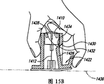
图15B是图15A中所示施加装置的侧剖面图。Figure 15B is a side cross-sectional view of the applicator shown in Figure 15A.
具体实施方式Detailed ways
在附图中,相同的附图标记表示相同或者极其类似的元件。为了便于对任何特定的元件的描述,附图标记中最显著的标号指的是该元件被首次引入的附图的图号(例如,元件304是在图3中被首次引入和描述的,元件1002是在图10中被首次引入和描述的)。In the figures, the same reference numbers designate the same or very similar elements. To facilitate the description of any particular element, the most prominent designation in a reference number refers to the figure number in which that element was first introduced (e.g., element 304 was first introduced and described in FIG. 3,
现将结合图1-15B对本发明的某些实施例的许多具体细节进行描述,以便全面地理解这些实施例。但是,本领域中的技术人员应该理解的是,本发明可具有其他的实施例,或者可在没有下面描述的几种具体细节的情况下实现本发明。另外,下面未审定的美国专利申请的全部内容被引入这里作为参考:09/452,663;09/452,508;09/451,795;09/451,799;09/452,510;09/451,800;09/451,796;09/451,547;09/667,183(代理人证号为33734.8002US00);以及29/130,210(代理人证号为33734.8001.US01)。Numerous specific details of certain embodiments of the invention will now be described in conjunction with FIGS. 1-15B in order to provide a comprehensive understanding of these embodiments. It will be understood, however, by those skilled in the art that the present invention is capable of other embodiments or of being practiced without several of the specific details described below. Additionally, the entire contents of the following copending U.S. patent applications are incorporated herein by reference: 09/452,663; 09/452,508; 09/451,795; 09/451,799; 09/452,510; 09/667,183 (Attorney ID 33734.8002US00); and 29/130,210 (Attorney ID 33734.8001.US01).
本发明描述了用于附着、使用和取下通过刺入覆盖组织的皮肤而将电流输送到患者的组织区域的探针,诸如电疗电极的方法和设备。电流由患者体外的控制单元产生并且通常具有特定的波形特征,诸如频率、振幅和脉冲宽度。根据将进行的处理和治疗,可采用一个包含阴极和阳极的一个电极或者其中至少一个用作阴极且至少一个用作阳极的多个电极。The present invention describes methods and apparatus for attaching, using and removing probes, such as electrotherapy electrodes, that deliver electrical current to an area of tissue of a patient by penetrating the skin overlying the tissue. The electrical current is generated by a control unit outside the patient's body and typically has specific waveform characteristics such as frequency, amplitude, and pulse width. Depending on the treatment and therapy to be performed, one electrode comprising a cathode and an anode or a plurality of electrodes, at least one of which acts as a cathode and at least one of which acts as an anode, may be employed.
图1-6和相关的说明大体上涉及一种根据本发明的一个实施例的施加装置。图7-13和相关的说明大体上涉及用于附着和取下根据本发明的实施例的施加装置的方法和装置。图14A-15B和相关的说明大体上涉及用于防止先前已经被插入过的经皮探针再次插入的方法和设备。1-6 and the associated description generally relate to an application device according to an embodiment of the present invention. 7-13 and the associated description generally relate to methods and devices for attaching and detaching applicator devices according to embodiments of the present invention. 14A-15B and the associated description generally relate to methods and apparatus for preventing reinsertion of a percutaneous probe that has been previously inserted.
图1是根据本发明第一实施例的包括壳体102的探针施加装置100的分解顶部轴侧视图。壳体102包括一个搁置在患者皮肤上的底座104、一个使底座104附着于皮肤上的附着元件106(诸如粘结垫)以及一个被装在底座104中的套筒108。底座104包括皮肤接合表面和罩壳。例如,皮肤接合表面可以为环形唇部105,而罩壳可以是一个以所需的角度从唇部105伸出的管107。滑动器110装配在套筒108中并且支撑探针112而相对于底座104移动。探针112包括电极、诊断探针、药物输送针、抽液针或者其他经过皮肤或者经皮装置。1 is an exploded top isometric view of a probe application device 100 including a housing 102 according to a first embodiment of the present invention. Housing 102 includes a base 104 that rests on the patient's skin, an attachment element 106 , such as an adhesive pad, to attach base 104 to the skin, and a sleeve 108 received within
在操作中,滑动器110可在套筒108内上下滑动以插入和收回探针112。滑动器110和套筒108可作为一个整体相对于底座104转动到所选择的位置。在该实施例的一个方面中,滑动器110、套筒108和底座104都与壳体102的中心轴线114是同轴的,而探针112相对于中心轴线114偏置或者偏心。因此,当滑动器110和套筒108作为一个整体相对于底座104一起转动时,探针112围绕中心轴线114转动到一个相对于患者皮肤表面的新的位置。在一个替代实施例中,滑动器110和套筒108不必相对于壳体102转动,并且探针112可沿着中心轴线114轴向移动。在另一个替代实施例中,可省去套筒108并且壳体102可单独引导滑动器110。In operation, the slider 110 can slide up and down within the sleeve 108 to insert and retract the stylet 112 . Slider 110 and sleeve 108 are rotatable as a unit relative to base 104 to a selected position. In one aspect of this embodiment, slider 110 , sleeve 108 , and
图2是根据本发明一个实施例的接合滑动器110(图1)且移动该滑动器110和探针112(图1)的致动器200的分解顶部轴侧视图。在该实施例的一个方面中,致动器200包括一个可脱开地接合滑动器110并且使滑动器110在套筒108(图1)内轴向位移的柱塞202。致动器200还包括一个被触点支撑件206支撑并且被弹簧210偏压在探针112上的接触板204。电线(在图2中未示出)与接触板204相连并且穿过环管208和盖子212,用以使接触板204与电源相连。FIG. 2 is an exploded top isometric view of an actuator 200 engaging slider 110 ( FIG. 1 ) and moving the slider 110 and probe 112 ( FIG. 1 ), according to one embodiment of the invention. In one aspect of this embodiment, the actuator 200 includes a plunger 202 that releasably engages the slider 110 and axially displaces the slider 110 within the sleeve 108 (FIG. 1). Actuator 200 also includes a contact plate 204 supported by contact support 206 and biased against probe 112 by spring 210 . Electrical wires (not shown in FIG. 2 ) are connected to the contact plate 204 and passed through the grommet 208 and the cover 212 for connecting the contact plate 204 to a power source.
图3是根据本发明一个实施例的参照图1和图2的上述设备100在位于患者或者受者皮肤300的表面上时的侧向剖视图。在该实施例的一个方面中,底座104具有平坦的下表面,并且利用附着元件106可脱开地附着在皮肤300上。因此,底座104稳固地安装在皮肤300上,并且底座104的唇部105被构造成能够以直角将探针112引入到皮肤300中。或者根据本发明的另一个实施例,底座104的唇部105可被构造成以另一个角度将探针112引入到皮肤300中。探针管302向下突出到底座104的下方并且包括一个能够使探针112穿过的管通道304。因此,探针管302在底座104下方压迫和拉伸皮肤300,同时使皮肤300在管通道304内略微向上凸出。结果,患者在探针112进入皮肤300的过程中几乎不会感觉到和/或感到恐慌。FIG. 3 is a side cross-sectional view of the apparatus 100 described above with reference to FIGS. 1 and 2 when positioned on the surface of a patient's or recipient's skin 300 according to one embodiment of the present invention. In one aspect of this embodiment,
通过握持致动器200的盖子212并且下压柱塞202直至滑动器110接触探针管302的顶部而使探针112插入到皮肤300中。如果需要使探针112改变在皮肤300中的位置,那么提升柱塞202直至滑动器110与套筒108的套筒边缘306对准,如图3中所示。接着,医生握持套筒边缘306并且在底座104内围绕中心轴线114将套筒108、滑动器110和柱塞202转动到一个相对于皮肤表面300的新位置上。当滑动器110绕轴线114转动时,偏心的探针112和探针管302绕轴线114转动到该新位置上。一旦套筒108处于新位置上,医生就压下柱塞202以将探针112重新插入该新位置中。The probe 112 is inserted into the skin 300 by holding the cap 212 of the actuator 200 and depressing the plunger 202 until the slider 110 contacts the top of the probe tube 302 . If it is desired to reposition the probe 112 in the skin 300, the plunger 202 is raised until the slider 110 is aligned with the sleeve edge 306 of the sleeve 108, as shown in FIG. Next, the physician grasps the sleeve edge 306 and rotates the sleeve 108 , slider 110 and plunger 202 within the
当探针112包括一个用于经皮的电神经刺激的电极时,医生接着将导线308连接在探针112和能够为探针112提供电能的控制单元310之间。在一个实施例中,控制单元310提供具有高达20毫安的振幅、大约4Hz至大约5Hz的频率以及大约50微秒至大约1毫秒的脉冲宽度的经过电流调节和电流平衡的波形。在其他实施例中,控制单元310可提供具有其他特性的波形。在另一些实施例中,除了或者代替控制电流外,控制单元310可控制供给探针112的电压。When the probe 112 includes an electrode for percutaneous electrical nerve stimulation, the physician then connects the wire 308 between the probe 112 and the control unit 310 capable of providing electrical power to the probe 112 . In one embodiment, the control unit 310 provides a current regulated and current balanced waveform having an amplitude of up to 20 mA, a frequency of about 4 Hz to about 5 Hz, and a pulse width of about 50 microseconds to about 1 millisecond. In other embodiments, the control unit 310 may provide waveforms with other characteristics. In other embodiments, the control unit 310 may control the voltage supplied to the probe 112 in addition to or instead of controlling the current.
在一个实施例中,壳体102在整个治疗过程中在患者皮肤300上保持定位,在该实施例的一个方面中这可持续30分钟。当完成治疗时,可通过首先使探针112从皮肤300中缩回,接着按照相反的顺序执行上述步骤来取下壳体102。然后,可在使附着元件106脱离皮肤300后使壳体102从皮肤300上抬起。在该实施例的一个方面中,附着元件106可包括一个无粘性的舌片部分312和一个有助于取下附着元件106的带孔狭缝314。对于每一个后续治疗,可以将一个新壳体102附着在患者上。或者,壳体102可在多个疗程保持附着在患者上。In one embodiment, the housing 102 remains in place on the patient's skin 300 throughout the treatment, which in one aspect of this embodiment can last up to 30 minutes. When the treatment is complete, the housing 102 can be removed by first retracting the probe 112 from the skin 300, and then performing the above steps in reverse order. The housing 102 may then be lifted off the skin 300 after the attachment element 106 is detached from the skin 300 . In one aspect of this embodiment, the attachment element 106 can include a non-adhesive tab portion 312 and a perforated slot 314 to facilitate removal of the attachment element 106 . For each subsequent treatment, a new housing 102 may be attached to the patient. Alternatively, housing 102 may remain attached to the patient for multiple sessions.
图4是图1和图3中所示底座104的一个实施例的顶部轴侧视图。图5是图2和图3中所示套筒108的一个实施例的底部轴侧视图。现参见图4和图5,底座104可以包括一个尺寸可适于转动地接收套筒108的中空接收筒402。接收筒402可具有内表面404,该内表面404具有由沟槽壁407限定的并且尺寸适于接收套筒108的相应套筒定位器舌片502的多个轴向底座沟槽406。在该实施例的一个方面中,套筒108可包括两个相对朝向的套筒定位器舌片502(图5中可看到其中一个),并且底座104包括两对相对朝向的轴向沟槽406。在其他的实施例中,套筒108可具有不同数量的套筒定位器舌片502,和/或底座104可具有不同数量的轴向底座沟槽406。在任何一个实施例中,医生可通过握持设置在套筒边缘306周围的手指扣牢部504并且顺时针或者逆时针地拧转套筒108而使套筒108相对于底座104转动,以迫使套筒定位器舌片502从一对轴向底座沟槽406中脱出并且进入下一对轴向底座沟槽406中。FIG. 4 is a top isometric view of one embodiment of the base 104 shown in FIGS. 1 and 3 . FIG. 5 is a bottom isometric view of one embodiment of the sleeve 108 shown in FIGS. 2 and 3 . Referring now to FIGS. 4 and 5 , the
在图4和图5中所示的一个实施例的一个方面,医生至少受到在底座104中从内表面404径向向内突出并且被接收在套筒108中的对应保持沟槽506中的保持唇部408的限制(或者防止)使得套筒108不能相对于底座104轴向移动。保持唇部408可具有向下渐缩的侧表面,在安装过程中,当套筒108初始被插入到底座104中时,该向下渐缩的侧表面咬合在保持沟槽506中。保持唇部408也可具有朝下的台阶表面,该表面与保持沟槽506的相应的朝上表面接合,以防止套筒108相对于底座104进一步轴向移动,同时使套筒108能够相对于底座104转动(在图3中也示出)。In one aspect of one embodiment shown in FIGS. 4 and 5 , the physician is retained at least by corresponding retention grooves 506 projecting radially inwardly in the base 104 from the
在一个实施例中,套筒108具有两个套筒轴向引导沟槽508,当套筒舌片502位于另一对轴向底座沟槽406中时,该套筒轴向引导沟槽508与底座104中的相应的一对轴向底座沟槽406对准。每一个套筒轴向引导沟槽508包括与一个轴向底座沟槽406共同延伸的下部510和在轴向底座沟槽406上方的边缘306中的上部512。该构造可防止医生使探针112(图3)相对于患者皮肤300(图3)同时轴向和横向移动。如下面将参照图6所述的,该构造也可防止医生使探针112相对于皮肤300横向移动直至探针112从皮肤300完全缩回。In one embodiment, the sleeve 108 has two sleeve axial guide grooves 508 that align with the sleeve tongue 502 when the sleeve tongue 502 is seated in the other pair of
图6是根据本发明一个实施例的位于已经被插入到施加装置100的底座104中的套筒108上方的滑动器110的顶部轴侧视图。在该实施例的一个方面中,在组装过程中通过操作组装工具600使滑动器110安装在壳体102中。一旦被安装好之后,医生可使滑动器110相对于壳体102移动,医生可使滑动器110与致动器200接合。下面将对组装工具600和致动器200的操作进行说明。FIG. 6 is a top isometric view of slider 110 positioned over sleeve 108 that has been inserted into
在一个实施例中,组装工具600包括以可拆卸的方式被容放在滑动器110中的相应圆形沟槽604中的薄壁筒602。组装工具600还可包括被容放在滑动器110的相应栓槽608中的两个组装栓606(图6中可看到其中一个)。每一个栓槽608包括一个轴向部分610和一个横向部分612。横向部分612可具有形状适于接收组装栓606的弯曲的上表面614。为了使组装工具600与滑动器110接合,安装人员使组装工具600的组装栓606与栓槽608的轴向部分610对准。接着,安装人员将组装工具600下降到滑动器110的圆形沟槽604中。当组装栓606到达栓槽608的轴向部分610的底部时,安装人员顺时针转动组装工具600直至组装栓606到达栓槽608的横向部分612的顺时针端部。然后,安装人员可在组装工具600上施加向下的压力以使弹簧210(图3)将组装栓606向上偏压在栓槽608的上表面614上,并且保持滑动器110与工具600接合。在该实施例的一个方面中,每一个组装栓606与滑动器110的外表面620平齐或者从该表面620下凹,以便不干涉在套筒108中的滑动器110的运动,这将在下面进行描述。In one embodiment, the assembly tool 600 includes a thin-walled barrel 602 removably received in a corresponding circular groove 604 in the slider 110 . The assembly tool 600 may also include two assembly pegs 606 (one of which is visible in FIG. 6 ) that are received in corresponding peg slots 608 of the slider 110 . Each keyway 608 includes an axial portion 610 and a transverse portion 612 . Lateral portion 612 may have a curved upper surface 614 shaped to receive assembly peg 606 . To engage assembly tool 600 with slider 110 , the installer aligns assembly peg 606 of assembly tool 600 with axial portion 610 of key slot 608 . Next, the installer lowers the assembly tool 600 into the circular groove 604 of the slider 110 . When the assembly key 606 reaches the bottom of the axial portion 610 of the key slot 608 , the installer turns the assembly tool 600 clockwise until the assembly key 606 reaches the clockwise end of the lateral portion 612 of the key slot 608 . The installer can then apply downward pressure on assembly tool 600 to cause spring 210 ( FIG. 3 ) to bias assembly peg 606 upward against upper surface 614 of peg slot 608 and keep slider 110 engaged with tool 600 . In one aspect of this embodiment, each assembly pin 606 is flush with the outer surface 620 of the slider 110 or is recessed from the surface 620 so as not to interfere with the movement of the slider 110 in the sleeve 108, which will be Described below.
在一个实施例中,滑动器110包括两个引导件618(图6中可看到其中一个)。套筒108的边缘306具有一个平的横向唇部615,它带有相对朝向的孔616(图6中可看到其中一个),每一个孔616的尺寸适于接收一个引导件618。在该实施例的一个方面中,一个引导件618可大于另一个引导件,并且一个孔616可大于另一个孔,从而可以使滑动器110仅沿一个方向被插入到套筒108中。因此,探针112将自动地与探针管302(图3)对准。或者,两个引导件618可以具有基本上相同的尺寸。在任何一个实施例中,组装工具600和滑动器110作为一个整体朝壳体102下降,直至引导件618被接收在边缘306的孔616中。In one embodiment, slider 110 includes two guides 618 (one of which is visible in FIG. 6 ). The edge 306 of the sleeve 108 has a flat transverse lip 615 with oppositely facing holes 616 (one of which can be seen in FIG. 6 ), each sized to receive a guide 618 . In one aspect of this embodiment, one guide 618 can be larger than the other guide, and one hole 616 can be larger than the other hole, so that slider 110 can only be inserted into sleeve 108 in one direction. Thus, the probe 112 will automatically align with the probe tube 302 (FIG. 3). Alternatively, the two guides 618 may have substantially the same size. In either embodiment, the assembly tool 600 and slider 110 are lowered as a unit toward the housing 102 until the guide 618 is received in the hole 616 of the rim 306 .
套筒108的边缘306可具有在每一个孔616和一个套筒轴向引导沟槽508的相应上部512之间延伸的横向引导沟槽622。每一个横向引导沟槽622部分地由沟槽底板624限定并且包括一个能够限制滑动器110的逆时针转动的转动止档626。横向引导沟槽622还可以包括一个从唇部306轴向向下地延伸到横向引导沟槽622中以限制滑动器110转动的套筒转动限制元件627。套筒轴向限制元件628轴向向下地偏离边缘615并且可径向向内地延伸以接合引导件618并限制滑动器110轴向运动。因此,如下面将更加详细描述的那样,套筒转动限制元件627与滑动器110的滑动器转动限制元件630相互合作,并且套筒轴向限制元件628与滑动器110的滑动器轴向限制元件632相合作。The rim 306 of the sleeve 108 may have a lateral guide groove 622 extending between each bore 616 and a corresponding upper portion 512 of one of the sleeve axial guide grooves 508 . Each lateral guide groove 622 is defined in part by a groove floor 624 and includes a rotation stop 626 capable of limiting counterclockwise rotation of the slider 110 . The lateral guide groove 622 may also include a sleeve rotation limiting member 627 extending axially downward from the lip 306 into the lateral guide groove 622 to limit the rotation of the slider 110 . Sleeve axial limiting element 628 is offset axially downward from rim 615 and is extendable radially inward to engage guide 618 and limit slider 110 axial movement. Thus, as will be described in more detail below, the sleeve rotation limiting element 627 cooperates with the slider rotation limiting element 630 of the slider 110 and the sleeve axial limiting element 628 cooperates with the slider axial limiting element of the slider 110. 632 cooperate with each other.
当滑动器110和组装工具600被下降到孔616中时,组装栓606被接收在套筒边缘306的横向引导沟槽622中,并且其中一个组装栓606在位置“A”处(在图6中由虚线所示)。引导件618也位于与组装栓606相邻的横向引导沟槽622中。当安装人员顺时针转动组装工具600时,滑动器转动限制元件630经过转动止档626的斜面634并且接着抵靠着套筒转动限制元件628地卡扣定位。组装栓606现在处于位置“B”处,并且在滑动器110中的栓槽608的轴向部分610与孔616对准。由于转动止档626的后表面636是平坦的,并且直接面对滑动器转动限制元件630,所以防止了滑动器110逆时针转过转动止档626。这时,滑动器转动限制元件630与套筒转动止档626接合,并且滑动器轴向限制元件632沿着处于边缘615正下方的套筒轴向限制元件628的上表面设置。现在将滑动器110安装在壳体102中,并且通过轻微下压工具600以使组装栓606与栓槽608的上表面614脱开而取下组装工具600。接着,安装人员逆时针转动组装工具600,直至组装栓606在位置“A”处与栓槽608的轴向部分610对准,并且提升组装工具600离开滑动器110和壳体102。在该实施例的一个方面中,现在可以将装有滑动器110的壳体102与独立的致动器200一起提供给最终使用者或者医生。When the slider 110 and assembly tool 600 are lowered into the holes 616, the assembly pegs 606 are received in the lateral guide grooves 622 of the sleeve edge 306, and one of the assembly pegs 606 is at position "A" (in FIG. shown by the dotted line). Guide 618 is also located in lateral guide groove 622 adjacent assembly peg 606 . As the installer turns assembly tool 600 clockwise, slider rotation limiting element 630 passes ramp 634 of rotation stop 626 and then snaps into place against sleeve rotation limiting element 628 . Assembly peg 606 is now in position “B” and axial portion 610 of peg slot 608 in slider 110 is aligned with bore 616 . Since the rear surface 636 of the rotation stop 626 is flat and directly faces the slider rotation limiting member 630, the slider 110 is prevented from rotating counterclockwise past the rotation stop 626. At this point, the slider rotation limiting element 630 is engaged with the sleeve rotation stop 626 and the slider axial limiting element 632 is disposed along the upper surface of the sleeve axial limiting element 628 directly below the edge 615 . The slider 110 is now installed in the housing 102 and the assembly tool 600 is removed by depressing the tool 600 slightly to disengage the assembly peg 606 from the upper surface 614 of the peg slot 608 . Next, the installer turns assembly tool 600 counterclockwise until assembly key 606 aligns with axial portion 610 of key slot 608 at position “A” and lifts assembly tool 600 off slider 110 and housing 102 . In one aspect of this embodiment, the housing 102 housing the slider 110 can now be provided to an end user or physician together with a separate actuator 200 .
为了操作探针施加装置100,如上面参照图3所述的,医生将施加装置100附着在患者的皮肤300上。然后,医生通过使致动器栓640与壳体102的边缘306中的孔616对准并且将致动器栓640下降到孔616中而使图6所示致动器200与滑动器110接合。医生转动致动器200,直至致动器栓640接合滑动器110。此时,一个致动器栓640位于在横向引导沟槽622中的位置“B”处。随后,医生继续顺时针转动致动器200,迫使每一个引导件618经过相应的套筒转动限制元件627,直至一个致动器栓640处于位置“C”上。这时,引导件618和致动器栓640与套筒轴向引导沟槽508的上部512和底座轴向沟槽406对准。当引导件618的滑动器转动限制元件630“卡嗒”地经过套筒转动限制元件627时,医生接收到表示滑动器110已处于能够使探针112插入患者的合适的转动位置的机械和/或声音反馈。To operate probe application device 100 , the physician attaches application device 100 to the patient's skin 300 as described above with reference to FIG. 3 . The physician then engages the actuator 200 shown in FIG. . The physician turns the actuator 200 until the actuator pin 640 engages the slider 110 . At this point, one actuator peg 640 is located at position “B” in the lateral guide groove 622 . The physician then continues to rotate the actuator 200 clockwise, forcing each guide 618 past the corresponding sleeve rotation limiting element 627 until one of the actuator pins 640 is in position "C". At this point, guide 618 and actuator peg 640 are aligned with upper portion 512 of sleeve axial guide groove 508 and base
为了将探针112插入患者,医生在致动器200上施加一向下的作用力,将滑动器轴向限制元件632压在套筒轴向限制元件628上,直至滑动器轴向限制元件632“卡嗒”经过套筒轴向限制元件628,提供给医生表示滑动器110处于能够继续插入的合适位置上的额外的机械式反馈。于是,医生下压致动器200,向下迫使滑动器110通过套筒108,并且其机械阻力小于在套筒轴向限制元件628上方卡扣连接滑动器轴向限制元件632所需的机械阻力。滑动器110通过套筒108的向下移动使探针112向下移动通过探针管302。在该实施例的一个方面中,滑动器110的重量足以使其自由下降,并且仅由医生施加的作用力作为将探针112插入患者所需的作用力。当滑动器110向下移动时,套筒轴向引导沟槽508沿着一个轴向路径引导所述引导件618,并且底座轴向沟槽406沿着一个平行的轴向路径接收和引导致动器栓640。To insert stylet 112 into the patient, the physician applies a downward force on actuator 200, pressing slider axial limiter 632 against sleeve axial limiter 628 until slider axial limiter 632" The "click" past the sleeve axial restraint element 628 provides the physician with additional mechanical feedback that the slider 110 is in the proper position for continued insertion. The physician then depresses the actuator 200, forcing the slider 110 downwardly through the sleeve 108 with less mechanical resistance than would be required to snap engage the slider axial limiting element 632 over the sleeve axial limiting element 628 . Downward movement of slider 110 through sleeve 108 moves probe 112 down through probe tube 302 . In one aspect of this embodiment, the weight of the slider 110 is sufficient to allow it to fall freely, and only the force applied by the physician is required to insert the stylet 112 into the patient. As the slider 110 moves downward, the sleeve axial guide groove 508 guides the guide 618 along an axial path, and the base
如果需要重新定位探针112,则医生利用引导所述引导件618的套筒轴向引导沟槽508和引导致动器栓640的底座轴向沟槽406使致动器200和滑动器110向上移动,以确保探针112仅在轴向上移动。如果医生试图在滑动器110已经完全收回之前转动边缘306从而使滑动器轴向限制元件632在套筒轴向限制元件628上方卡扣到位,那么致动器栓640将支撑在底座轴向沟槽406的沟槽壁407(图4)上,防止这样的转动。医生继续提升致动器200和滑动器110,直至滑动器轴向限制元件632在套筒轴向限制元件628上方回咬,以确保一个致动器栓640在横向引导沟槽622中处于位置“C”。此时,探针112已经完全从皮肤300(图3)缩回并且套筒轴向限制元件628可阻止滑动器110和探针112向下滑动,直至医生准备重新插入探针112。如上面参照图3所述的,接着医生通过握住筒108的边缘306并使边缘306相对于底座104转动,使滑动器110、探针112、致动器200和套筒108作为一个整体转动。一旦探针112已经转动到新位置上,医生就重新插入探针112。因此,套筒轴向沟槽508、底座轴向沟槽406和边缘306的横向沟槽622依次相对于皮肤300轴向地和横向地引导探针112。If the stylet 112 needs to be repositioned, the physician brings the actuator 200 and slider 110 upward using the sleeve axial guide groove 508 which guides the guide 618 and the base
如上面参照图1-6所述的探针施加装置100的一个实施例的一个特征为,壳体102、滑动器110和致动器200的布置使得医生能够相对于患者的皮肤横向地重新定位探针112(通过使探针112围绕中心轴线114转动),并且允许医生轴向地移动探针112(用于探针插入和缩回),但防止医生横向地移动探针112直至探针112完全从患者身上取出。该特征的一个优点是,医生几乎不能通过在探针112仍然插入患者时横向地移动探针112而伤害患者。One feature of one embodiment of the probe applying device 100 as described above with reference to FIGS. probe 112 (by rotating the probe 112 about the central axis 114), and allows the physician to move the probe 112 axially (for probe insertion and retraction), but prevents the physician from moving the probe 112 laterally until the probe 112 Remove completely from patient. One advantage of this feature is that the physician can hardly injure the patient by moving the stylet 112 laterally while the stylet 112 is still inserted into the patient.
参照图1-6的上述施加装置100的一个实施例的另一个优点为,医生可相对于患者皮肤300重新定位探针112且不用使整个壳体102脱离患者身体。例如,当探针112是电刺激针时,医生可将壳体102紧固在处于需要接收电刺激的神经区域的大致部位上方的皮肤300上,接着通过在壳体102保持附着在患者皮肤300上的同时使探针112相对于壳体102转动而对位置进行微调。在一个实施例中,探针112可相对于中心轴线114偏移0.09英寸,并且可定位于四个预选位置中的一个上,而且每一个预选位置与相邻的位置大约相距0.127英寸的距离。在其他的实施例中,探针112可移动到更多或者更少的预选位置,并且预选位置之间可保持更大或者更小的间距。Another advantage of an embodiment of the applicator 100 described above with reference to FIGS. 1-6 is that the physician can reposition the probe 112 relative to the patient's skin 300 without detaching the entire housing 102 from the patient's body. For example, when the probe 112 is an electrical stimulation needle, the physician may fasten the housing 102 to the skin 300 over approximately the area of the nerve that needs to receive electrical stimulation, and then by maintaining the housing 102 attached to the patient's skin 300 At the same time, the probe 112 is rotated relative to the housing 102 to fine-tune the position. In one embodiment, the probe 112 can be offset 0.09 inches from the central axis 114 and can be positioned at one of four preselected locations, each preselected location being approximately 0.127 inches from an adjacent location. In other embodiments, the probe 112 can be moved to more or fewer preselected positions, and the preselected positions can be kept at a greater or lesser spacing.
图7是根据本发明一个实施例的与参照图1和图3的上述实施例大致类似的附着元件106的一部分的轴侧视图。在该实施例的一个方面中,附着元件106可包括一个可压缩的泡沫体,它具有通过可脱开的结合部分707与第二部分704相连的第一部分702。该可脱开的结合部分707可与一条撕开线712对准,该撕开线在施加装置100(图1)用后允许使医生将第二部分704的至少一部分从第一部分702上撕下。FIG. 7 is an isometric view of a portion of an attachment element 106 generally similar to the embodiment described above with reference to FIGS. 1 and 3 , according to one embodiment of the present invention. In one aspect of this embodiment, the attachment element 106 may comprise a compressible foam having a first portion 702 connected to a second portion 704 by a releasable joint 707 . The releasable joining portion 707 can be aligned with a tear line 712 that allows a physician to tear at least a portion of the second portion 704 from the first portion 702 after the application device 100 ( FIG. 1 ) has been used. .
在该实施例的一个方面中,附着元件106可以包括一个延伸过第一部分702和第二部分704的面朝下的粘合表面714。例如,附着元件106可包括由加利福尼亚州的Scapa Medical of Inglewood生产的带有丙烯酸片状粘结剂的聚乙烯泡沫。因此,通过使第一部分702的面朝下的粘合表面714与唇部105的面朝上的表面接合,可使第一部分702粘结到壳体102(图1)的环形唇部105(图1)上。在其他的实施例中,可利用其他装置将第一部分702附着在唇部105上。在任何一个上述实施例中,第二部分704的粘合表面714可被粘结到患者皮肤上。在该实施例的一个方面中,覆层705(诸如涂覆纸片)最初可附着在第二部分704的粘合表面714上,并且可在使粘合表面714与患者皮肤接合之前被取下。In one aspect of this embodiment, the attachment element 106 can include a downwardly facing adhesive surface 714 extending across the first portion 702 and the second portion 704 . For example, attachment element 106 may comprise polyethylene foam with acrylic sheet adhesive produced by Scapa Medical of Inglewood, California. Thus, the first portion 702 can be bonded to the annular lip 105 ( FIG. 1) on. In other embodiments, other means may be used to attach the first portion 702 to the lip 105 . In any of the above embodiments, the adhesive surface 714 of the second portion 704 can be bonded to the patient's skin. In one aspect of this embodiment, the covering 705, such as a coated paper sheet, can initially be attached to the adhesive surface 714 of the second portion 704 and can be removed prior to engaging the adhesive surface 714 with the patient's skin. .
在一个实施例中,可脱开的结合部分707包括一个具有能够使第一部分702与第二部分704相连的连接部分708的带孔狭缝314,并且在连接部分708之间具有间隙710。例如,第一部分702可与第二部分704整体地形成,并且可通过沿着撕开线712在间隔开的位置上对附着元件106穿孔而形成间隙710。或者,第一部分702最初可与第二部分704分离且可与例如由液体粘合剂点滴形成的连接部分708相连。在其他实施例中,可脱开的结合部分707的结构可具有其他构造形式,诸如下面参照图8A-图8C所述的那些。在这些实施例中的任何一个中,附着元件106趋于在可脱开的结合部分707处并且沿着撕开线712优先分离,这是由于可脱开的结合部分707的撕裂强度小于第一部分702和第二部分704的撕裂强度。In one embodiment, the releasable joining portion 707 includes a perforated slit 314 having connecting portions 708 for connecting the first portion 702 to the second portion 704 with gaps 710 therebetween. For example, first portion 702 may be integrally formed with second portion 704 and gap 710 may be formed by perforating attachment element 106 at spaced apart locations along tear line 712 . Alternatively, the first portion 702 may initially be separated from the second portion 704 and may be connected with a connection portion 708 formed, for example, by a drop of liquid adhesive. In other embodiments, the configuration of the releasable coupling portion 707 may have other configurations, such as those described below with reference to FIGS. 8A-8C . In any of these embodiments, the attachment element 106 tends to separate preferentially at the releasable bonding portion 707 and along the tear line 712 because the tear strength of the releasable bonding portion 707 is less than that of the releasable bonding portion 707. The tear strength of the first part 702 and the second part 704.
图8A是根据本发明另一个实施例的附着元件806a的一部分的侧剖面图。在该实施例的一个方面,附着元件806a可包括其形状分别与上面参照图7所述的第一部分702和第二部分704基本类似的第一部分802a和第二部分804a。附着元件806a还可包括在第一部分802a和第二部分804a之间的可脱开的结合部分807a。在该实施例的一个方面中,第一部分802a和第二部分804a可具有大于可脱开的结合部分807a的厚度T2的材料厚度T1。因此,当相反的作用力施加在第一部分802a和第二部分804a上时,附着元件806a将会在可脱开的结合部分807a处分离。Figure 8A is a side cross-sectional view of a portion of an attachment element 806a according to another embodiment of the invention. In one aspect of this embodiment, the attachment element 806a can include a first portion 802a and a second portion 804a that are substantially similar in shape to the first portion 702 and the second portion 704, respectively, described above with reference to FIG. 7 . The attachment element 806a may also include a releasable joint portion 807a between the first portion 802a and the second portion 804a. In one aspect of this embodiment, the first portion 802a and the second portion 804a can have a material thickness T1 greater than the thickness T2 of the releasable joining portion 807a. Thus, when opposing forces are applied to the first portion 802a and the second portion 804a, the attachment element 806a will separate at the releasable joint portion 807a.
图8B是根据本发明又一个实施例的附着元件806b的一部分的侧剖面图。在该实施例的一个方面中,附着元件806b可以包括与可脱开的结合部分807b相连的第一部分802b和第二部分804b。第一部分802b和第二部分804b分别可包括多个叠置的层809。在可脱开的结合部分807b的区域中,可取消一个或者多个层809,在相邻的层809之间留有间隙810。因此,可脱开的结合部分807b将弱于第一部分802b和第二部分804b,并当医生将相反的作用力施加在第一部分802b和第二部分804b上时,可脱开的结合部分807b将会被撕开。Figure 8B is a side cross-sectional view of a portion of an
图8C是根据本发明再一个实施例的具有由可脱开的结合部分807c与第二部分804c连接的第一部分802c的附着元件806c的一部分的侧剖面图。在该实施例的一个方面中,形成可脱开的结合部分807c的材料可具有与形成第一部分802c和第二部分804c的材料大致相同的厚度,但可具有低于第一部分802c或者第二部分804c的撕裂强度。因此,当相反的作用力施加在第一部分802c和第二部分804c上时,第二部分804c的至少一部分会在可脱开的结合部分807c处与第一部分802c分离。8C is a side cross-sectional view of a portion of an
图9-11示意性地示出了用于取下根据本发明的一个实施例的施加装置900的步骤。首先参见图9,施加装置900可包括与上面参照图1-6所述基本类似的壳体102。具有固定在壳体102上的内部902和附着在患者皮肤表面930上的外部904的附着元件906可脱离地使施加装置900与患者相连。例如,附着元件906可具有与患者皮肤表面930接合的粘合下表面914。在该实施例的一个方面中,第二部分904可包括一个可便于医生握持的向上突出的舌片916。或者,第二部分904可包括一个基本上与患者皮肤930共面的舌片,如图1和图3中所示。在任何一个实施例中,附着元件906可包括会沿着撕开线912分离的可脱开的结合部分907。9-11 schematically illustrate steps for removing an
如图10中所示,医生1000可将舌片916抓在大拇指1002和食指1004之间并且向上拉动舌片916。附着元件906的第二部分904会沿着撕开线912与第一部分902分离。当第二部分904与第一部分902分离时,它也破坏了粘合下表面914与患者皮肤930之间的粘结,使施加装置900能够与患者分离。图11示出了在已经与患者皮肤930脱开后的施加装置900,并且第二部分904至少部分地与第一部分902分离。As shown in FIG. 10 ,
参照图1-11的上述施加装置的实施例的一个特征是,当使施加装置与患者皮肤分离时,附着元件的第二部分可以至少部分地与第一部分分离或者被撕下。该特征的一个优点为,撕开的附着元件清楚地表明,该施加装置先前已经附着在患者身上,可因此向医生发出信号不能再次使用该施加装置。因此,医生几乎不可能传播由重复使用的经皮探针来传递的病原体。One feature of the embodiments of the applicator described above with reference to FIGS. 1-11 is that the second part of the attachment element can be at least partially detached from the first part or torn off when the applicator is detached from the patient's skin. One advantage of this feature is that the tearing of the attachment element clearly indicates that the applicator has been previously attached to the patient and can thus signal to the physician that the applicator cannot be used again. Thus, it is nearly impossible for physicians to spread pathogens delivered by reusable percutaneous probes.
该构造的另一个优点是,撕开的附着元件可以使医生难以将施加装置重新附着在同一或者不同的患者身上。例如,现在参照图11,很难仅利用附着元件906将施加装置900牢固地支撑在患者皮肤上,这是由于附着元件906的第二部分904的大部分与第一部分902分离。因此,第二部分904的分离部分不能为施加装置900提供支撑,即使该分离部分具有可重新附着在患者身上的足够的剩余粘结强度。另外,第二部分904的粘结强度在使用一次后被削弱,这是由于(a)一部分粘结剂留在患者皮肤300上;和/或(b)留在第二部分904上的粘结剂可能因已经粘上来自于患者皮肤的物质(诸如死皮肤细胞)而不太粘了。Another advantage of this configuration is that a torn attachment element can make it difficult for the physician to reattach the applicator device to the same or a different patient. For example, referring now to FIG. 11 , it is difficult to securely support
尽管施加装置900已经清楚地表明它已经被使用过,并且重新附着用过的施加装置900是困难的,但是,医生仍然有可能将施加装置900重新附着到同一或者另一个受者身上(在施加装置900已经被取下后)。例如,医生可在第二部分704的撕裂部分和第一部分702或者壳体102之间涂覆单独的粘结剂(诸如粘合膜或者液体粘结剂)。接着,医生可将第二部分904的粘合下表面914重新附着在皮肤表面上。因此,医生可在施加装置900和同一或者另一个患者之间重新建立牢固的连接。在其他的实施例中,医生可利用其他方法重新附着施加装置900。Although the
图12是根据本发明另一个实施例的可脱开地附着在受者的皮肤表面1230上的施加装置1200的局部示意性轴侧视图。在该实施例的一个方面中,施加装置1200可以包括一个具有凸缘1205的壳体1202和最初与壳体1202分离的附着元件1206。附着元件1206可具有一个粘合下表面1208和一个粘合上表面1209。下覆层1211最初抵靠着粘合下表面1208,上覆层1210最初抵靠着粘合上表面1209。附着元件1206可任选地包括通过如图12中的虚线所示的可脱开的结合部分1207与第二部分1204相连的第一部分1202。Figure 12 is a partial schematic isometric view of an applicator device 1200 releasably attached to a skin surface 1230 of a recipient according to another embodiment of the present invention. In one aspect of this embodiment, the applicator device 1200 can include a housing 1202 having a flange 1205 and an attachment element 1206 initially separate from the housing 1202 . Attachment element 1206 may have a lower adhesive surface 1208 and an upper adhesive surface 1209 . The lower cover layer 1211 is initially against the adhesive lower surface 1208 and the upper cover layer 1210 is initially against the adhesive upper surface 1209 . Attachment element 1206 may optionally include a first portion 1202 connected to a second portion 1204 by a releasable joining portion 1207 as shown in phantom in FIG. 12 .
在操作中,医生(未示出)将下覆层1211从下表面1208上取下(如箭头A所示)并且将下表面1208附着在皮肤表面1230上。接着,医生可将上覆层1210从附着元件1206的上表面1209上取下(如箭头B所示)并且将施加装置1200的凸缘1205附着在现已露出的上表面1209上。为了使施加装置1200从皮肤表面1230上取下,医生可使附着元件1206的下表面1208与皮肤表面1230分离,同时使附着元件1206保持附着在凸缘1205上。因此,附着元件1206的上表面1209对于凸缘1205的亲和力可强于下表面1208对于皮肤表面1230的亲和力。或者,医生可首先将凸缘1205从附着元件1206的上表面1209上取下,接着将附着元件1206从皮肤表面1230上取下。因此,上表面1209对于凸缘1205的亲和力可小于下表面1208对于皮肤表面1230的亲和力。In operation, a physician (not shown) removes the underlying covering 1211 from the lower surface 1208 (as indicated by arrow A) and attaches the lower surface 1208 to the skin surface 1230 . Next, the physician may remove the overlay 1210 from the upper surface 1209 of the attachment element 1206 (as indicated by arrow B) and attach the flange 1205 of the applicator 1200 to the now exposed upper surface 1209 . To remove applicator device 1200 from skin surface 1230 , the physician may detach lower surface 1208 of attachment element 1206 from skin surface 1230 while leaving attachment element 1206 attached to flange 1205 . Accordingly, upper surface 1209 of attachment element 1206 may have a stronger affinity for flange 1205 than lower surface 1208 for skin surface 1230 . Alternatively, the physician may first remove flange 1205 from upper surface 1209 of attachment element 1206 and then remove attachment element 1206 from surface 1230 of the skin. Accordingly, the affinity of the upper surface 1209 for the flange 1205 may be less than the affinity of the lower surface 1208 for the skin surface 1230 .
在任何一个上述实施例中,附着元件1206可大大减少重新附着在相同或者不同的受者上的可能性。例如,当附着元件1206包括一个打孔的可脱开的结合部分1207时,附着元件的第二部分1204可以与上面参照图7-11所述的基本类似的方式与第一部分1202至少部分分离。或者,由于上面参照图7-11描述的一些原因,附着元件1206的下表面1208上的粘结剂的重新附着能力可大大降低。In any of the above-described embodiments, the attachment element 1206 can greatly reduce the likelihood of reattachment to the same or a different recipient. For example, when the attachment element 1206 includes a perforated releasable coupling portion 1207, the second portion 1204 of the attachment element can be at least partially separated from the first portion 1202 in a manner substantially similar to that described above with reference to FIGS. 7-11. Alternatively, the reattachment ability of the adhesive on the lower surface 1208 of the attachment element 1206 may be greatly reduced for several reasons described above with reference to FIGS. 7-11.
图13是根据本发明另一个实施例的可脱开地与受者皮肤表面1330相连的施加装置1300的局部示意性轴侧视图。在该实施例的一个方面中,施加装置1300可包括一个具有凸缘1305的壳体1302。医生可例如利用按钮式喷雾施加器或者泵动喷射施加装置1320将可脱开的粘结剂1306施加在凸缘1305的下表面上。接着,医生可使凸缘1305与皮肤表面1330接合。为了使施加装置1300与皮肤表面1330分离,医生可在凸缘1305和皮肤表面1330之间的结合处或其附近设置一种剥离剂1325。例如,医生可利用喷射施加装置1330散开剥离剂1325的射流。在一个实施例中,粘结剂1306可以包括诸如氰基丙烯酸或者氰基丙烯酸酯的胶粘剂,剥离剂1325可以包括酮。在其他实施例中,粘结剂1306和剥离剂1325可以包括其他化学成分。在这些实施例中的任何一个中,以化学的方式使施加装置1300和皮肤表面1330之间的粘结脱开的一个优点是,该技术可在受者的皮肤1330上施加很小的机械作用力,这可使具有敏感皮肤的受者感到更舒适。Figure 13 is a partial schematic isometric view of an
图14A是具有至少限制在开始使用后的经皮探针的运动的止档元件1422的施加装置1400的轴侧视图。在该实施例的一个方面中,施加装置1400可以包括一个利用大致根据上述实施例的粘结剂附着元件1406(位于基本上平坦的附着平面1436中)附着在患者上的壳体1402。在该实施例的一个方面中,壳体1402可包括一个从环形唇部1405向上伸出的管1407。管1407可具有一个孔1420,其中设置止档元件1422。止档元件1422可包括一个被构造成将由医生的手指1004接合的舌片部分1424和一个被构造成至少限制经皮探针的运动的接合部分1426,下面将参照图14B-15B进行更详细的描述。14A is an isometric view of an
图14B是上面参照图14A所述的施加装置1400的局部示意性侧剖视图。如图14B中所示,施加装置1400可以包括一个具有一经皮探针1412的滑动器1410。滑动器1410可相对于壳体1402滑动(并且任选地可转动),从而以与上述基本类似的方式使用和收回经皮探针1412。在该实施例的一个方面中,管孔1420的下边缘1430可向下倾斜并且平行于接合部分1426的上边缘1428。在该实施例的另一个方面中,下边缘1430的最靠内的点1432可位于上边缘1428的最靠上的点1424下方。因此,下边缘1430可将上边缘1428锁定在所选择的一个位置上,下面将参照图15A-15B进行更详细的描述。Figure 14B is a partial schematic side cross-sectional view of the
现在参照图15A,医生1000可使管1407与大拇指1002接合并且使舌片部分1424与食指1004接合。然后,医生可使舌片部分1424朝管1407转动以使环形唇部1405的一部分和粘结剂附着元件1406沿着折线1413折叠。当止档元件1422向内转动时,接合部分1426从一个非限制位置(与管1407的壁共面)移动到一个限制位置(在管1407的壁内侧并且在滑动器1410的正下方)。现在参照图15B,由止档元件1422限制滑动器1410和探针1412向下移动到使用位置。至少阻止止档元件1422移动到其非限制位置,这是因为接合部分1426的最靠上的点1434现在“卡嗒”移动到一个处于孔下边缘1430的最靠内的点1432上方并且位于内部的一个位置。Referring now to FIG. 15A ,
上面参照图14A-15B描述的施加装置1400的一个实施例的一个特征是,当止档元件1422处于其限制位置时,止档元件1422可防止滑动器1410和探针1412使用。另一个特征是,当施加装置1400正脱离皮肤表面时,止档元件1422可从非限制位置移动到限制位置。这些特征的一个优点是,施加装置1400的构造可在收回探针1412之前对试图取下施加装置的医生发出警告。例如,如果滑动器1410处于其向下位置,并且探针1412在患者皮肤中使用,那么滑动器1410将干涉接合部分1426的向内动作,并且医生将不能使接合部分1426“卡嗒”移动到孔1420中。One feature of one embodiment of the
这些特征的另一个优点是,一旦止档元件1422移动到其限制位置以防止滑动器1410向下移动(如图15B中所示),施加装置1400就不会被轻易地重复使用。另外,部分折叠的环形唇部1405和向内转动的止档元件1422可为医生提供表明施加装置1400已被用过并且不适于重复使用的视觉指示。因此,止档元件1422可减小通过重复使用的施加装置和经皮探针1412传输病原体的可能性。Another advantage of these features is that once the
上述特征的又一个优点是,当医生将舌片部分1424枢转到管1407中时,舌片部分1424可向上拉动部分附着元件1406。因此,舌片部分1424可起动附着元件1406与患者皮肤的分离并且使施加装置1400的继续分离变得更容易。Yet another advantage of the above features is that when the physician pivots the
上述特征的再一个优点是,可阻止医生将初次使用过的施加装置1400重新附着在另一个受者上。例如,当止档元件1422的接合部分1426移动到其限制位置时,舌片部分1424可向上拉动部分附着元件1406并且使附着元件1406的该部分偏离基本上平坦的附着平面1436。限制舌片部分1424使附着元件1406的该部分移动返回附着平面1436,这是因为由孔1420的下端1432限制接合部分1426向外转动。当部分附着元件1406偏离附着平面1436时,施加装置1400不会那么容易且牢固地附着在患者上。Yet another advantage of the above features is that it prevents the physician from reattaching the first-
尽管施加装置1400已经清楚地表明它已经被使用过,并且设有止档元件1422,但是,医生仍然能够重复使用施加装置1400。例如,医生可在舌片部分1424上施加向下作用力以迫使止档元件1422的最靠上的点1434向外经过孔下边缘1430的最靠内的点1432。在其他实施例中,医生可以其他方式避开止档元件1422。Even though the
根据上面的内容,应该理解的是,为了说明而在这里描述了一些具体的实施例,但在不脱离本发明的精神和保护范围的情况下可做出各种变化。因此,本发明不限于此,而是由附属的权利要求限定。From the foregoing it should be appreciated that specific embodiments have been described herein for purposes of illustration, but that various changes may be made without departing from the spirit and scope of the invention. Accordingly, the invention is not limited thereto but only by the appended claims.
Claims (72)
Applications Claiming Priority (2)
| Application Number | Priority Date | Filing Date | Title |
|---|---|---|---|
| US09/928,044 US6904324B2 (en) | 1999-12-01 | 2001-08-11 | Method and apparatus for deploying a percutaneous probe |
| US09/928,044 | 2001-08-11 |
Publications (2)
| Publication Number | Publication Date |
|---|---|
| CN1553821A true CN1553821A (en) | 2004-12-08 |
| CN100368035C CN100368035C (en) | 2008-02-13 |
Family
ID=25455627
Family Applications (1)
| Application Number | Title | Priority Date | Filing Date |
|---|---|---|---|
| CNB028178491A Expired - Fee Related CN100368035C (en) | 2001-08-11 | 2002-08-09 | Methods and devices for using percutaneous probes |
Country Status (10)
| Country | Link |
|---|---|
| US (1) | US6904324B2 (en) |
| EP (1) | EP1418979B1 (en) |
| JP (1) | JP4194039B2 (en) |
| KR (1) | KR20040058175A (en) |
| CN (1) | CN100368035C (en) |
| AT (1) | ATE389434T1 (en) |
| AU (1) | AU2002324675B2 (en) |
| CA (1) | CA2456760A1 (en) |
| DE (1) | DE60225696D1 (en) |
| WO (1) | WO2003015867A2 (en) |
Cited By (3)
| Publication number | Priority date | Publication date | Assignee | Title |
|---|---|---|---|---|
| CN107773843A (en) * | 2016-08-31 | 2018-03-09 | 艾科漫医疗设备公司 | For the acupuncture needle for the improvement for sensing and stimulating |
| CN108135746A (en) * | 2016-01-14 | 2018-06-08 | 泰尔茂株式会社 | Affixed component and medical instrument |
| CN115868973A (en) * | 2021-09-27 | 2023-03-31 | 上海移宇科技股份有限公司 | Analyte detection device mounting unit |
Families Citing this family (37)
| Publication number | Priority date | Publication date | Assignee | Title |
|---|---|---|---|---|
| ATE352334T1 (en) * | 2001-05-18 | 2007-02-15 | Deka Products Lp | INFUSION DEVICE FOR A LIQUID PUMP |
| US8034026B2 (en) | 2001-05-18 | 2011-10-11 | Deka Products Limited Partnership | Infusion pump assembly |
| ES2450465T3 (en) * | 2001-10-18 | 2014-03-24 | Uroplasty, Inc. | Nerve Electrostimulation System |
| US8812114B2 (en) | 2001-10-18 | 2014-08-19 | Uroplasty, Inc. | Lead set for nerve stimulator and method of operation thereof |
| US7104965B1 (en) * | 2003-06-06 | 2006-09-12 | The General Hospital Corporation | Interactive system and method for peripheral nerve mapping and blocking |
| US8467875B2 (en) | 2004-02-12 | 2013-06-18 | Medtronic, Inc. | Stimulation of dorsal genital nerves to treat urologic dysfunctions |
| US7120499B2 (en) * | 2004-02-12 | 2006-10-10 | Ndi Medical, Llc | Portable percutaneous assemblies, systems and methods for providing highly selective functional or therapeutic neuromuscular stimulation |
| US8086318B2 (en) * | 2004-02-12 | 2011-12-27 | Ndi Medical, Llc | Portable assemblies, systems, and methods for providing functional or therapeutic neurostimulation |
| JP2007531562A (en) * | 2004-02-12 | 2007-11-08 | エヌディーアイ メディカル, エルエルシー | Portable assembly, system and method for providing functional or therapeutic neuromuscular stimulation |
| US7283867B2 (en) | 2004-06-10 | 2007-10-16 | Ndi Medical, Llc | Implantable system and methods for acquisition and processing of electrical signals from muscles and/or nerves and/or central nervous system tissue |
| US9205255B2 (en) | 2004-06-10 | 2015-12-08 | Medtronic Urinary Solutions, Inc. | Implantable pulse generator systems and methods for providing functional and/or therapeutic stimulation of muscles and/or nerves and/or central nervous system tissue |
| US8165692B2 (en) | 2004-06-10 | 2012-04-24 | Medtronic Urinary Solutions, Inc. | Implantable pulse generator power management |
| US9308382B2 (en) | 2004-06-10 | 2016-04-12 | Medtronic Urinary Solutions, Inc. | Implantable pulse generator systems and methods for providing functional and/or therapeutic stimulation of muscles and/or nerves and/or central nervous system tissue |
| US20070066995A1 (en) * | 2004-06-10 | 2007-03-22 | Ndi Medical, Llc | Implantable pulse generator systems and methods for providing functional and/or therapeutic stimulation of muscles and/or nerves and/or central nervous system tissue |
| US8195304B2 (en) | 2004-06-10 | 2012-06-05 | Medtronic Urinary Solutions, Inc. | Implantable systems and methods for acquisition and processing of electrical signals |
| US7761167B2 (en) | 2004-06-10 | 2010-07-20 | Medtronic Urinary Solutions, Inc. | Systems and methods for clinician control of stimulation systems |
| USD558882S1 (en) * | 2006-03-14 | 2008-01-01 | Unomedical Limited | Biomedical electrode for attachment to skin |
| US9480846B2 (en) | 2006-05-17 | 2016-11-01 | Medtronic Urinary Solutions, Inc. | Systems and methods for patient control of stimulation systems |
| US7668598B2 (en) * | 2006-05-18 | 2010-02-23 | Uroplasty, Inc. | Method and apparatus for stimulating a nerve of a patient |
| US20080097549A1 (en) | 2006-09-01 | 2008-04-24 | Colbaugh Michael E | Electrode Assembly and Method of Using Same |
| US8121696B2 (en) * | 2007-02-02 | 2012-02-21 | Rommel P. Vallero | Topical analgesia using electrical and vibration stimuli |
| US7962206B2 (en) * | 2008-01-10 | 2011-06-14 | Arkady Glukhovsky | Methods for implanting electronic implants within the body |
| JP5676445B2 (en) * | 2008-08-01 | 2015-02-25 | エヌディーアイ メディカル, エルエルシー | Portable assembly, system and method for providing functional or therapeutic neural stimulation |
| US8223028B2 (en) | 2008-10-10 | 2012-07-17 | Deka Products Limited Partnership | Occlusion detection system and method |
| US8267892B2 (en) | 2008-10-10 | 2012-09-18 | Deka Products Limited Partnership | Multi-language / multi-processor infusion pump assembly |
| US8262616B2 (en) | 2008-10-10 | 2012-09-11 | Deka Products Limited Partnership | Infusion pump assembly |
| US8708376B2 (en) | 2008-10-10 | 2014-04-29 | Deka Products Limited Partnership | Medium connector |
| US8016789B2 (en) | 2008-10-10 | 2011-09-13 | Deka Products Limited Partnership | Pump assembly with a removable cover assembly |
| US8066672B2 (en) | 2008-10-10 | 2011-11-29 | Deka Products Limited Partnership | Infusion pump assembly with a backup power supply |
| US9180245B2 (en) | 2008-10-10 | 2015-11-10 | Deka Products Limited Partnership | System and method for administering an infusible fluid |
| WO2012046231A2 (en) * | 2010-10-04 | 2012-04-12 | Nervomatrix Ltd. | Electrode for finding points of low impedance and applying electrical stimulation thereto |
| US8750956B2 (en) * | 2011-09-21 | 2014-06-10 | Edward Allen Riess | Method and devices for its employ for reducing disease-transfer risks |
| US9153900B2 (en) * | 2011-10-14 | 2015-10-06 | Biomet Manufacturing Corp. | Implantable subcutaneous electrical socket and percutaneous plug |
| KR101778268B1 (en) | 2016-03-28 | 2017-09-13 | 서울대학교산학협력단 | Medical-treatment electrode assembly |
| KR102583347B1 (en) * | 2016-05-31 | 2023-09-27 | 한국전자기술연구원 | Tibial Nerve Stimulation Signal Generation Device and Method |
| KR20210080415A (en) | 2018-10-22 | 2021-06-30 | 메드트로닉 좀드 인코퍼레이티드 | Stimulation probe assembly and method of use |
| CN117838534B (en) * | 2023-04-10 | 2025-01-14 | 唐俊 | Acupuncture point acupuncture locator |
Family Cites Families (90)
| Publication number | Priority date | Publication date | Assignee | Title |
|---|---|---|---|---|
| US3090151A (en) * | 1958-02-14 | 1963-05-21 | Stewart Trigg | Underwater spear gun |
| US3030959A (en) * | 1959-09-04 | 1962-04-24 | Praemeta | Surgical lancet for blood sampling |
| US3208452A (en) * | 1960-09-08 | 1965-09-28 | Panray Parlam Corp | Surface treating device |
| US3943935A (en) * | 1973-09-07 | 1976-03-16 | Cameron Robert C | Disposable earlobe piercing apparatus |
| US3938526A (en) * | 1974-05-20 | 1976-02-17 | Anderson Weston A | Electrical acupuncture needle heater |
| US3983881A (en) * | 1975-05-21 | 1976-10-05 | Telectronics Pty. Limited | Muscle stimulator |
| DE2657053C3 (en) * | 1975-12-19 | 1980-01-31 | Societe D'etudes Et D'applications Techniques S.E.D.A.T., Irigny, Rhone (Frankreich) | Device comprising an acupuncture needle and a device for piercing the same |
| US4153059A (en) | 1977-10-25 | 1979-05-08 | Minnesota Mining And Manufacturing Company | Urinary incontinence stimulator system |
| DE2800039C2 (en) * | 1978-01-02 | 1984-06-20 | Horst Dr.Med. 6700 Ludwigshafen Kief | Acupuncture device |
| US4207903A (en) * | 1978-04-28 | 1980-06-17 | Medtronic, Inc. | Device for screwing body tissue electrode into body tissue |
| US4256116A (en) * | 1978-07-03 | 1981-03-17 | Technion Research And Development Foundation, Limited | Transcutaneous pain reliever |
| US4431000A (en) * | 1978-11-29 | 1984-02-14 | Gatron Corporation | Transcutaneous nerve stimulator with pseusorandom pulse generator |
| US4281659A (en) * | 1979-03-12 | 1981-08-04 | Roche Medical Electronics Inc. | Applying and securing percutaneous or transcutaneous probes to the skin especially for fetal monitoring |
| US4284856A (en) | 1979-09-24 | 1981-08-18 | Hochmair Ingeborg | Multi-frequency system and method for enhancing auditory stimulation and the like |
| FR2473882A1 (en) * | 1980-01-21 | 1981-07-24 | Deloffre Auguste | APPARATUS FOR DETECTING ACUPUNCTURE POINTS OF A PATIENT AND FOR APPLYING ELECTRICAL STIMULATION SIGNALS TO DETECT POINTS |
| US4381012A (en) | 1980-09-24 | 1983-04-26 | Wallant International Trade, Inc. | Electrode placement device |
| FR2500309A3 (en) | 1981-02-25 | 1982-08-27 | Faiveley Sa | Electrical pulse generator producing analgesic effect - applies short rise time pulses, which are amplitude modulated and passed through wobbulator to affect human tissues |
| FR2500745B1 (en) | 1981-03-02 | 1986-07-04 | Dervieux Dominique | DETECTION AND STIMULATION APPARATUS FOR ACUPUNCTURE TREATMENT |
| US4437467A (en) * | 1981-12-11 | 1984-03-20 | American Home Products Corporation | Apparatus for monitoring fetal heartbeat and the like |
| US4512351A (en) * | 1982-11-19 | 1985-04-23 | Cordis Corporation | Percutaneous lead introducing system and method |
| CA1215128A (en) * | 1982-12-08 | 1986-12-09 | Pedro Molina-Negro | Electric nerve stimulator device |
| US4556064A (en) * | 1983-01-25 | 1985-12-03 | Bruce Pomeranz | Electrotherapy acupuncture apparatus and method |
| GB8406509D0 (en) * | 1984-03-13 | 1984-04-18 | Bio Medical Res Ltd | Electrical stimulation of muscle |
| US4583549A (en) * | 1984-05-30 | 1986-04-22 | Samir Manoli | ECG electrode pad |
| FR2567762B1 (en) | 1984-07-20 | 1989-04-14 | Simonin Philippe | DEVICE FOR THE AESTHETIC TREATMENT OF THE SKIN |
| US4979508A (en) | 1984-10-09 | 1990-12-25 | Beck Stephen C | Apparatus for generating phosphenes |
| DE3502913C1 (en) * | 1985-01-29 | 1986-07-03 | Günter Prof. Dr.rer.nat. 5100 Aachen Rau | Sensor for non-invasive detection of electrophysiological values |
| US4765310A (en) * | 1985-11-01 | 1988-08-23 | Dynatens Research Corporation | Electrical and magnetic pain treatment device |
| US4686996A (en) * | 1985-12-24 | 1987-08-18 | Paul Ulbrich | Electrode assembly for sensing heart activity |
| USD297047S (en) * | 1986-12-01 | 1988-08-02 | Hon Edward H | Sensor support plate for use with an external medical monitor device |
| US5117826A (en) * | 1987-02-02 | 1992-06-02 | Staodyn, Inc. | Combined nerve fiber and body tissue stimulation apparatus and method |
| USD318330S (en) * | 1987-10-15 | 1991-07-16 | Doty James R | Unipolar spiral coil electrode for monitoring the electrical activity of the brain |
| US5012811A (en) * | 1988-02-09 | 1991-05-07 | American Home Products Corporation | Fetal electrode product with protective cap |
| US4934371A (en) * | 1988-02-09 | 1990-06-19 | American Home Products Corporation | Fetal electrode product |
| US4895154A (en) * | 1988-02-19 | 1990-01-23 | Staodynamics, Inc. | Electronic stimulating device for enhanced healing of soft tissue wounds |
| US4949734A (en) * | 1988-08-25 | 1990-08-21 | Gerald Bernstein | Shield for electrosurgical device |
| US5094242A (en) * | 1988-11-07 | 1992-03-10 | Regents Of The University Of California | Implantable nerve stimulation device |
| US5211175A (en) * | 1988-11-07 | 1993-05-18 | Regents Of The University Of California | Method for implanting electra-acupuncture needle |
| GB8904998D0 (en) * | 1989-03-04 | 1989-04-19 | Matthews Tony | Anaesthetising apparatus |
| US4953564A (en) * | 1989-08-23 | 1990-09-04 | Medtronic, Inc. | Screw-in drug eluting lead |
| US5036850A (en) * | 1989-08-25 | 1991-08-06 | Staodyn, Inc. | Biphasic pulse output stage for electronic stimulating device |
| GB8924559D0 (en) * | 1989-11-01 | 1989-12-20 | Capel Ifor D | Method for transcranial electrotherapy |
| US5054486A (en) * | 1990-05-31 | 1991-10-08 | Mamoru Yamada | Remedial techniques for the treatment of painful disorders such as intervertebral disc hernia and the like |
| CN2086141U (en) * | 1991-03-06 | 1991-10-09 | 鲁兆麟 | Cementation safe moxibustion medicine |
| CN2090259U (en) * | 1991-04-13 | 1991-12-11 | 杨一工 | Convenient intervallic moxibustion |
| GB2255719A (en) | 1991-05-11 | 1992-11-18 | Tony Matthews | Electro-therapy apparatus |
| US5851223A (en) | 1991-05-21 | 1998-12-22 | Medi Consultants, Inc. | Combination non-intrusive analgesic neuroaugmentive system and method triple-modulated gigatens with optional bipolar spike |
| US5246014A (en) * | 1991-11-08 | 1993-09-21 | Medtronic, Inc. | Implantable lead system |
| US5255691A (en) * | 1991-11-13 | 1993-10-26 | Medtronic, Inc. | Percutaneous epidural lead introducing system and method |
| SE9201453L (en) * | 1992-05-08 | 1993-07-12 | Jens Schouenborg | MEDICAL DEVICE FOR RELIEFING THE PAIN CONDITION INCLUDING AN ELECTRIC PLATE |
| US5281218A (en) * | 1992-06-05 | 1994-01-25 | Cardiac Pathways Corporation | Catheter having needle electrode for radiofrequency ablation |
| DE4244690C2 (en) * | 1992-08-26 | 1995-03-16 | Hewlett Packard Gmbh | Insertion mechanism for a fetal scalp electrode |
| FR2703253B1 (en) * | 1993-03-30 | 1995-06-23 | Centre Nat Rech Scient | APPLICATOR OF ELECTRIC PULSES FOR TREATING BIOLOGICAL TISSUES. |
| US5439440A (en) * | 1993-04-01 | 1995-08-08 | Genetronics, Inc. | Electroporation system with voltage control feedback for clinical applications |
| US5702359A (en) * | 1995-06-06 | 1997-12-30 | Genetronics, Inc. | Needle electrodes for mediated delivery of drugs and genes |
| US5417719A (en) * | 1993-08-25 | 1995-05-23 | Medtronic, Inc. | Method of using a spinal cord stimulation lead |
| USD357069S (en) * | 1993-08-25 | 1995-04-04 | Quinton Instrument Company | Medical electrode |
| US5593429A (en) * | 1994-06-28 | 1997-01-14 | Cadwell Industries, Inc. | Needle electrode with depth of penetration limiter |
| US5810762A (en) * | 1995-04-10 | 1998-09-22 | Genetronics, Inc. | Electroporation system with voltage control feedback for clinical applications |
| AU6507096A (en) * | 1995-07-28 | 1997-02-26 | Cardiotronics International, Inc. | Disposable electro-dermal device |
| US5682233A (en) * | 1995-09-08 | 1997-10-28 | Integ, Inc. | Interstitial fluid sampler |
| US5649936A (en) * | 1995-09-19 | 1997-07-22 | Real; Douglas D. | Stereotactic guide apparatus for use with neurosurgical headframe |
| US5948008A (en) * | 1995-12-28 | 1999-09-07 | S.L.T. Japan Co., Ltd. | Apparatus for treatment of lumbar disc herniation |
| US6032064A (en) * | 1996-10-11 | 2000-02-29 | Aspect Medical Systems, Inc. | Electrode array system for measuring electrophysiological signals |
| US5873849A (en) * | 1997-04-24 | 1999-02-23 | Ichor Medical Systems, Inc. | Electrodes and electrode arrays for generating electroporation inducing electrical fields |
| US5861015A (en) * | 1997-05-05 | 1999-01-19 | Benja-Athon; Anuthep | Modulation of the nervous system for treatment of pain and related disorders |
| US5968063A (en) * | 1997-05-14 | 1999-10-19 | Jennifer Chu | Intramuscular stimulation therapy facilitating device and method |
| US5941845A (en) * | 1997-08-05 | 1999-08-24 | Irvine Biomedical, Inc. | Catheter having multiple-needle electrode and methods thereof |
| US6050992A (en) * | 1997-05-19 | 2000-04-18 | Radiotherapeutics Corporation | Apparatus and method for treating tissue with multiple electrodes |
| US5968011A (en) | 1997-06-20 | 1999-10-19 | Maersk Medical A/S | Subcutaneous injection set |
| US6055453A (en) * | 1997-08-01 | 2000-04-25 | Genetronics, Inc. | Apparatus for addressing needle array electrodes for electroporation therapy |
| US6208893B1 (en) * | 1998-01-27 | 2001-03-27 | Genetronics, Inc. | Electroporation apparatus with connective electrode template |
| US6009347A (en) * | 1998-01-27 | 1999-12-28 | Genetronics, Inc. | Electroporation apparatus with connective electrode template |
| US6035236A (en) * | 1998-07-13 | 2000-03-07 | Bionergy Therapeutics, Inc. | Methods and apparatus for electrical microcurrent stimulation therapy |
| US6355021B1 (en) | 1998-07-14 | 2002-03-12 | Maersk Medical A/S | Medical puncturing device |
| US6122547A (en) * | 1998-10-20 | 2000-09-19 | Benja-Athon; Anuthep | Consolidated electrical-lead acupuncture needle |
| US6269270B1 (en) | 1998-10-26 | 2001-07-31 | Birinder Bob Boveja | Apparatus and method for adjunct (add-on) therapy of Dementia and Alzheimer's disease utilizing an implantable lead and external stimulator |
| US6304785B1 (en) * | 1998-10-27 | 2001-10-16 | Huntington Medical Research Institute | Electrode insertion tool |
| US6117077A (en) | 1999-01-22 | 2000-09-12 | Del Mar Medical Systems, Llc | Long-term, ambulatory physiological recorder |
| US6341237B1 (en) * | 1999-10-25 | 2002-01-22 | Arthur F. Hurtado | Device for administrating electro-muscle stimulation and method of use |
| US6549797B1 (en) * | 1999-12-01 | 2003-04-15 | Vertis Neuroscience, Inc. | Electrode remover for a percutaneous electrical therapy system |
| US6539264B1 (en) * | 1999-12-01 | 2003-03-25 | Vertis Neuroscience, Inc. | Percutaneous electrical therapy system with sharp point protection |
| US6516226B1 (en) * | 1999-12-01 | 2003-02-04 | Vertis Neuroscience, Inc. | Percutaneous electrical therapy system for minimizing electrode insertion discomfort |
| US6529776B1 (en) | 1999-12-01 | 2003-03-04 | Vertis Neuroscience, Inc. | Method and apparatus for repositioning a percutaneous probe |
| US6560491B1 (en) * | 1999-12-01 | 2003-05-06 | Vertis Neuroscience, Inc. | Percutaneous electrical therapy system providing electrode axial support |
| US6493592B1 (en) * | 1999-12-01 | 2002-12-10 | Vertis Neuroscience, Inc. | Percutaneous electrical therapy system with electrode position maintenance |
| US6549810B1 (en) * | 1999-12-01 | 2003-04-15 | Vertis Neuroscience, Inc. | Percutaneous electrical therapy system with electrode depth control |
| US6556869B1 (en) * | 1999-12-01 | 2003-04-29 | Vertis Neuroscience, Inc. | Electrode introducer for a percutaneous electrical therapy system |
| USD443063S1 (en) * | 2000-08-25 | 2001-05-29 | Nexan Limited | Chest multisensor array |
| US6418046B1 (en) * | 2001-01-30 | 2002-07-09 | Motorola, Inc. | MRAM architecture and system |
-
2001
- 2001-08-11 US US09/928,044 patent/US6904324B2/en not_active Expired - Fee Related
-
2002
- 2002-08-09 JP JP2003520820A patent/JP4194039B2/en not_active Expired - Fee Related
- 2002-08-09 CN CNB028178491A patent/CN100368035C/en not_active Expired - Fee Related
- 2002-08-09 AU AU2002324675A patent/AU2002324675B2/en not_active Ceased
- 2002-08-09 KR KR10-2004-7002080A patent/KR20040058175A/en not_active Abandoned
- 2002-08-09 AT AT02759333T patent/ATE389434T1/en not_active IP Right Cessation
- 2002-08-09 EP EP02759333A patent/EP1418979B1/en not_active Expired - Lifetime
- 2002-08-09 DE DE60225696T patent/DE60225696D1/en not_active Expired - Lifetime
- 2002-08-09 CA CA002456760A patent/CA2456760A1/en not_active Abandoned
- 2002-08-09 WO PCT/US2002/025551 patent/WO2003015867A2/en not_active Ceased
Cited By (4)
| Publication number | Priority date | Publication date | Assignee | Title |
|---|---|---|---|---|
| CN108135746A (en) * | 2016-01-14 | 2018-06-08 | 泰尔茂株式会社 | Affixed component and medical instrument |
| US10894122B2 (en) | 2016-01-14 | 2021-01-19 | Terumo Kabushiki Kaisha | Application member and medical instrument |
| CN107773843A (en) * | 2016-08-31 | 2018-03-09 | 艾科漫医疗设备公司 | For the acupuncture needle for the improvement for sensing and stimulating |
| CN115868973A (en) * | 2021-09-27 | 2023-03-31 | 上海移宇科技股份有限公司 | Analyte detection device mounting unit |
Also Published As
| Publication number | Publication date |
|---|---|
| WO2003015867A2 (en) | 2003-02-27 |
| EP1418979B1 (en) | 2008-03-19 |
| HK1071858A1 (en) | 2005-08-05 |
| CN100368035C (en) | 2008-02-13 |
| US20030195599A1 (en) | 2003-10-16 |
| US6904324B2 (en) | 2005-06-07 |
| AU2002324675B2 (en) | 2007-10-04 |
| ATE389434T1 (en) | 2008-04-15 |
| DE60225696D1 (en) | 2008-04-30 |
| JP2004538107A (en) | 2004-12-24 |
| JP4194039B2 (en) | 2008-12-10 |
| CA2456760A1 (en) | 2003-02-27 |
| KR20040058175A (en) | 2004-07-03 |
| WO2003015867A3 (en) | 2003-11-06 |
| EP1418979A2 (en) | 2004-05-19 |
Similar Documents
| Publication | Publication Date | Title |
|---|---|---|
| CN100368035C (en) | Methods and devices for using percutaneous probes | |
| AU2002324675A1 (en) | Method and apparatus for deploying a percutaneous probe | |
| US8303982B2 (en) | Self-locating, multiple application, and multiple location medical patch systems and methods therefor | |
| RU2278623C2 (en) | Micro-protruding member's holder for power applicator | |
| US6129929A (en) | Patch applicator | |
| JP7775379B2 (en) | System for nerve regeneration therapy | |
| EP2032198B1 (en) | Transdermal therapeutic system reinforced by ultrasounds | |
| EP2308553B1 (en) | Electro-nerve stimulator system | |
| DE69401938T2 (en) | DEVICE FOR ELECTRIC TRANSFER DELIVERY OF ACTIVE SUBSTANCE | |
| CN1753704A (en) | Controls the depth of transdermal application | |
| US20030088276A1 (en) | Easy-to-use electrode and package | |
| JP6458958B2 (en) | Versatile defibrillation electrode pad assembly for adult and pediatric subjects | |
| CN103476455B (en) | There is the defibrillator electrode pad that two are peeled off tab | |
| MX2008015247A (en) | Mounting pad. | |
| JP2004538107A5 (en) | ||
| JP2003527891A (en) | Transcutaneous electrotherapy device and electrodes | |
| US11577074B2 (en) | Apparatus and method for nerve stimulation and/or monitoring | |
| US7308318B2 (en) | Percutaneous apparatus with electrical coupling | |
| HK1071858B (en) | Method and apparatus for deploying a percutaneous probe | |
| JP5089691B2 (en) | Transdermal patch | |
| CN105530915A (en) | Device with transdermal therapeutic system and positioning and penetration aid | |
| JP2024523360A5 (en) | ||
| CN1747763A (en) | Percutaneous apparatus with electrical coupling | |
| CN115804623A (en) | Remove smallpox device paster and contain device that removes smallpox of removing smallpox device paster | |
| HK1218073B (en) | Device with transdermal therapeutic system and positioning and penetration aid |
Legal Events
| Date | Code | Title | Description |
|---|---|---|---|
| C06 | Publication | ||
| PB01 | Publication | ||
| C10 | Entry into substantive examination | ||
| SE01 | Entry into force of request for substantive examination | ||
| REG | Reference to a national code |
Ref country code: HK Ref legal event code: DE Ref document number: 1071858 Country of ref document: HK |
|
| C14 | Grant of patent or utility model | ||
| GR01 | Patent grant | ||
| REG | Reference to a national code |
Ref country code: HK Ref legal event code: GR Ref document number: 1071858 Country of ref document: HK |
|
| C19 | Lapse of patent right due to non-payment of the annual fee | ||
| CF01 | Termination of patent right due to non-payment of annual fee |