CN1554043A - Input control device for accepting multiple input operations on a single control unit - Google Patents
Input control device for accepting multiple input operations on a single control unit Download PDFInfo
- Publication number
- CN1554043A CN1554043A CNA028175271A CN02817527A CN1554043A CN 1554043 A CN1554043 A CN 1554043A CN A028175271 A CNA028175271 A CN A028175271A CN 02817527 A CN02817527 A CN 02817527A CN 1554043 A CN1554043 A CN 1554043A
- Authority
- CN
- China
- Prior art keywords
- image display
- image
- rotation
- control device
- input control
- Prior art date
- Legal status (The legal status is an assumption and is not a legal conclusion. Google has not performed a legal analysis and makes no representation as to the accuracy of the status listed.)
- Pending
Links
Images



Classifications
-
- G—PHYSICS
- G05—CONTROLLING; REGULATING
- G05G—CONTROL DEVICES OR SYSTEMS INSOFAR AS CHARACTERISED BY MECHANICAL FEATURES ONLY
- G05G9/00—Manually-actuated control mechanisms provided with one single controlling member co-operating with two or more controlled members, e.g. selectively, simultaneously
- G05G9/02—Manually-actuated control mechanisms provided with one single controlling member co-operating with two or more controlled members, e.g. selectively, simultaneously the controlling member being movable in different independent ways, movement in each individual way actuating one controlled member only
- G05G9/04—Manually-actuated control mechanisms provided with one single controlling member co-operating with two or more controlled members, e.g. selectively, simultaneously the controlling member being movable in different independent ways, movement in each individual way actuating one controlled member only in which movement in two or more ways can occur simultaneously
- G05G9/047—Manually-actuated control mechanisms provided with one single controlling member co-operating with two or more controlled members, e.g. selectively, simultaneously the controlling member being movable in different independent ways, movement in each individual way actuating one controlled member only in which movement in two or more ways can occur simultaneously the controlling member being movable by hand about orthogonal axes, e.g. joysticks
- G05G9/04785—Manually-actuated control mechanisms provided with one single controlling member co-operating with two or more controlled members, e.g. selectively, simultaneously the controlling member being movable in different independent ways, movement in each individual way actuating one controlled member only in which movement in two or more ways can occur simultaneously the controlling member being movable by hand about orthogonal axes, e.g. joysticks the controlling member being the operating part of a switch arrangement
- G05G9/04788—Manually-actuated control mechanisms provided with one single controlling member co-operating with two or more controlled members, e.g. selectively, simultaneously the controlling member being movable in different independent ways, movement in each individual way actuating one controlled member only in which movement in two or more ways can occur simultaneously the controlling member being movable by hand about orthogonal axes, e.g. joysticks the controlling member being the operating part of a switch arrangement comprising additional control elements
- G05G9/04792—Manually-actuated control mechanisms provided with one single controlling member co-operating with two or more controlled members, e.g. selectively, simultaneously the controlling member being movable in different independent ways, movement in each individual way actuating one controlled member only in which movement in two or more ways can occur simultaneously the controlling member being movable by hand about orthogonal axes, e.g. joysticks the controlling member being the operating part of a switch arrangement comprising additional control elements for rotary control around the axis of the controlling member
-
- A—HUMAN NECESSITIES
- A61—MEDICAL OR VETERINARY SCIENCE; HYGIENE
- A61B—DIAGNOSIS; SURGERY; IDENTIFICATION
- A61B6/00—Apparatus or devices for radiation diagnosis; Apparatus or devices for radiation diagnosis combined with radiation therapy equipment
-
- A—HUMAN NECESSITIES
- A61—MEDICAL OR VETERINARY SCIENCE; HYGIENE
- A61B—DIAGNOSIS; SURGERY; IDENTIFICATION
- A61B6/00—Apparatus or devices for radiation diagnosis; Apparatus or devices for radiation diagnosis combined with radiation therapy equipment
- A61B6/46—Arrangements for interfacing with the operator or the patient
- A61B6/461—Displaying means of special interest
- A61B6/463—Displaying means of special interest characterised by displaying multiple images or images and diagnostic data on one display
-
- A—HUMAN NECESSITIES
- A61—MEDICAL OR VETERINARY SCIENCE; HYGIENE
- A61B—DIAGNOSIS; SURGERY; IDENTIFICATION
- A61B6/00—Apparatus or devices for radiation diagnosis; Apparatus or devices for radiation diagnosis combined with radiation therapy equipment
- A61B6/46—Arrangements for interfacing with the operator or the patient
- A61B6/467—Arrangements for interfacing with the operator or the patient characterised by special input means
-
- G—PHYSICS
- G05—CONTROLLING; REGULATING
- G05G—CONTROL DEVICES OR SYSTEMS INSOFAR AS CHARACTERISED BY MECHANICAL FEATURES ONLY
- G05G9/00—Manually-actuated control mechanisms provided with one single controlling member co-operating with two or more controlled members, e.g. selectively, simultaneously
- G05G9/02—Manually-actuated control mechanisms provided with one single controlling member co-operating with two or more controlled members, e.g. selectively, simultaneously the controlling member being movable in different independent ways, movement in each individual way actuating one controlled member only
- G05G9/04—Manually-actuated control mechanisms provided with one single controlling member co-operating with two or more controlled members, e.g. selectively, simultaneously the controlling member being movable in different independent ways, movement in each individual way actuating one controlled member only in which movement in two or more ways can occur simultaneously
- G05G9/047—Manually-actuated control mechanisms provided with one single controlling member co-operating with two or more controlled members, e.g. selectively, simultaneously the controlling member being movable in different independent ways, movement in each individual way actuating one controlled member only in which movement in two or more ways can occur simultaneously the controlling member being movable by hand about orthogonal axes, e.g. joysticks
-
- G—PHYSICS
- G05—CONTROLLING; REGULATING
- G05G—CONTROL DEVICES OR SYSTEMS INSOFAR AS CHARACTERISED BY MECHANICAL FEATURES ONLY
- G05G9/00—Manually-actuated control mechanisms provided with one single controlling member co-operating with two or more controlled members, e.g. selectively, simultaneously
- G05G9/02—Manually-actuated control mechanisms provided with one single controlling member co-operating with two or more controlled members, e.g. selectively, simultaneously the controlling member being movable in different independent ways, movement in each individual way actuating one controlled member only
- G05G9/04—Manually-actuated control mechanisms provided with one single controlling member co-operating with two or more controlled members, e.g. selectively, simultaneously the controlling member being movable in different independent ways, movement in each individual way actuating one controlled member only in which movement in two or more ways can occur simultaneously
- G05G9/047—Manually-actuated control mechanisms provided with one single controlling member co-operating with two or more controlled members, e.g. selectively, simultaneously the controlling member being movable in different independent ways, movement in each individual way actuating one controlled member only in which movement in two or more ways can occur simultaneously the controlling member being movable by hand about orthogonal axes, e.g. joysticks
- G05G9/04785—Manually-actuated control mechanisms provided with one single controlling member co-operating with two or more controlled members, e.g. selectively, simultaneously the controlling member being movable in different independent ways, movement in each individual way actuating one controlled member only in which movement in two or more ways can occur simultaneously the controlling member being movable by hand about orthogonal axes, e.g. joysticks the controlling member being the operating part of a switch arrangement
- G05G9/04788—Manually-actuated control mechanisms provided with one single controlling member co-operating with two or more controlled members, e.g. selectively, simultaneously the controlling member being movable in different independent ways, movement in each individual way actuating one controlled member only in which movement in two or more ways can occur simultaneously the controlling member being movable by hand about orthogonal axes, e.g. joysticks the controlling member being the operating part of a switch arrangement comprising additional control elements
- G05G9/04796—Manually-actuated control mechanisms provided with one single controlling member co-operating with two or more controlled members, e.g. selectively, simultaneously the controlling member being movable in different independent ways, movement in each individual way actuating one controlled member only in which movement in two or more ways can occur simultaneously the controlling member being movable by hand about orthogonal axes, e.g. joysticks the controlling member being the operating part of a switch arrangement comprising additional control elements for rectilinear control along the axis of the controlling member
-
- G—PHYSICS
- G06—COMPUTING OR CALCULATING; COUNTING
- G06F—ELECTRIC DIGITAL DATA PROCESSING
- G06F3/00—Input arrangements for transferring data to be processed into a form capable of being handled by the computer; Output arrangements for transferring data from processing unit to output unit, e.g. interface arrangements
- G06F3/01—Input arrangements or combined input and output arrangements for interaction between user and computer
- G06F3/03—Arrangements for converting the position or the displacement of a member into a coded form
- G06F3/033—Pointing devices displaced or positioned by the user, e.g. mice, trackballs, pens or joysticks; Accessories therefor
- G06F3/0338—Pointing devices displaced or positioned by the user, e.g. mice, trackballs, pens or joysticks; Accessories therefor with detection of limited linear or angular displacement of an operating part of the device from a neutral position, e.g. isotonic or isometric joysticks
-
- G—PHYSICS
- G06—COMPUTING OR CALCULATING; COUNTING
- G06F—ELECTRIC DIGITAL DATA PROCESSING
- G06F3/00—Input arrangements for transferring data to be processed into a form capable of being handled by the computer; Output arrangements for transferring data from processing unit to output unit, e.g. interface arrangements
- G06F3/01—Input arrangements or combined input and output arrangements for interaction between user and computer
- G06F3/03—Arrangements for converting the position or the displacement of a member into a coded form
- G06F3/033—Pointing devices displaced or positioned by the user, e.g. mice, trackballs, pens or joysticks; Accessories therefor
- G06F3/0362—Pointing devices displaced or positioned by the user, e.g. mice, trackballs, pens or joysticks; Accessories therefor with detection of one-dimensional [1D] translations or rotations of an operating part of the device, e.g. scroll wheels, sliders, knobs, rollers or belts
-
- A—HUMAN NECESSITIES
- A61—MEDICAL OR VETERINARY SCIENCE; HYGIENE
- A61B—DIAGNOSIS; SURGERY; IDENTIFICATION
- A61B6/00—Apparatus or devices for radiation diagnosis; Apparatus or devices for radiation diagnosis combined with radiation therapy equipment
- A61B6/02—Arrangements for diagnosis sequentially in different planes; Stereoscopic radiation diagnosis
- A61B6/03—Computed tomography [CT]
-
- A—HUMAN NECESSITIES
- A63—SPORTS; GAMES; AMUSEMENTS
- A63F—CARD, BOARD, OR ROULETTE GAMES; INDOOR GAMES USING SMALL MOVING PLAYING BODIES; VIDEO GAMES; GAMES NOT OTHERWISE PROVIDED FOR
- A63F2300/00—Features of games using an electronically generated display having two or more dimensions, e.g. on a television screen, showing representations related to the game
- A63F2300/10—Features of games using an electronically generated display having two or more dimensions, e.g. on a television screen, showing representations related to the game characterized by input arrangements for converting player-generated signals into game device control signals
- A63F2300/1043—Features of games using an electronically generated display having two or more dimensions, e.g. on a television screen, showing representations related to the game characterized by input arrangements for converting player-generated signals into game device control signals being characterized by constructional details
-
- G—PHYSICS
- G05—CONTROLLING; REGULATING
- G05G—CONTROL DEVICES OR SYSTEMS INSOFAR AS CHARACTERISED BY MECHANICAL FEATURES ONLY
- G05G9/00—Manually-actuated control mechanisms provided with one single controlling member co-operating with two or more controlled members, e.g. selectively, simultaneously
- G05G9/02—Manually-actuated control mechanisms provided with one single controlling member co-operating with two or more controlled members, e.g. selectively, simultaneously the controlling member being movable in different independent ways, movement in each individual way actuating one controlled member only
- G05G9/04—Manually-actuated control mechanisms provided with one single controlling member co-operating with two or more controlled members, e.g. selectively, simultaneously the controlling member being movable in different independent ways, movement in each individual way actuating one controlled member only in which movement in two or more ways can occur simultaneously
- G05G9/047—Manually-actuated control mechanisms provided with one single controlling member co-operating with two or more controlled members, e.g. selectively, simultaneously the controlling member being movable in different independent ways, movement in each individual way actuating one controlled member only in which movement in two or more ways can occur simultaneously the controlling member being movable by hand about orthogonal axes, e.g. joysticks
- G05G2009/04777—Manually-actuated control mechanisms provided with one single controlling member co-operating with two or more controlled members, e.g. selectively, simultaneously the controlling member being movable in different independent ways, movement in each individual way actuating one controlled member only in which movement in two or more ways can occur simultaneously the controlling member being movable by hand about orthogonal axes, e.g. joysticks with additional push or pull action on the handle
-
- G—PHYSICS
- G05—CONTROLLING; REGULATING
- G05G—CONTROL DEVICES OR SYSTEMS INSOFAR AS CHARACTERISED BY MECHANICAL FEATURES ONLY
- G05G9/00—Manually-actuated control mechanisms provided with one single controlling member co-operating with two or more controlled members, e.g. selectively, simultaneously
- G05G9/02—Manually-actuated control mechanisms provided with one single controlling member co-operating with two or more controlled members, e.g. selectively, simultaneously the controlling member being movable in different independent ways, movement in each individual way actuating one controlled member only
- G05G9/04—Manually-actuated control mechanisms provided with one single controlling member co-operating with two or more controlled members, e.g. selectively, simultaneously the controlling member being movable in different independent ways, movement in each individual way actuating one controlled member only in which movement in two or more ways can occur simultaneously
- G05G9/047—Manually-actuated control mechanisms provided with one single controlling member co-operating with two or more controlled members, e.g. selectively, simultaneously the controlling member being movable in different independent ways, movement in each individual way actuating one controlled member only in which movement in two or more ways can occur simultaneously the controlling member being movable by hand about orthogonal axes, e.g. joysticks
- G05G2009/04781—Manually-actuated control mechanisms provided with one single controlling member co-operating with two or more controlled members, e.g. selectively, simultaneously the controlling member being movable in different independent ways, movement in each individual way actuating one controlled member only in which movement in two or more ways can occur simultaneously the controlling member being movable by hand about orthogonal axes, e.g. joysticks with additional rotation of the controlling member
-
- H—ELECTRICITY
- H01—ELECTRIC ELEMENTS
- H01H—ELECTRIC SWITCHES; RELAYS; SELECTORS; EMERGENCY PROTECTIVE DEVICES
- H01H25/00—Switches with compound movement of handle or other operating part
- H01H25/04—Operating part movable angularly in more than one plane, e.g. joystick
- H01H25/041—Operating part movable angularly in more than one plane, e.g. joystick having a generally flat operating member depressible at different locations to operate different controls
- H01H2025/043—Operating part movable angularly in more than one plane, e.g. joystick having a generally flat operating member depressible at different locations to operate different controls the operating member being rotatable around wobbling axis for additional switching functions
-
- H—ELECTRICITY
- H01—ELECTRIC ELEMENTS
- H01H—ELECTRIC SWITCHES; RELAYS; SELECTORS; EMERGENCY PROTECTIVE DEVICES
- H01H25/00—Switches with compound movement of handle or other operating part
-
- Y—GENERAL TAGGING OF NEW TECHNOLOGICAL DEVELOPMENTS; GENERAL TAGGING OF CROSS-SECTIONAL TECHNOLOGIES SPANNING OVER SEVERAL SECTIONS OF THE IPC; TECHNICAL SUBJECTS COVERED BY FORMER USPC CROSS-REFERENCE ART COLLECTIONS [XRACs] AND DIGESTS
- Y10—TECHNICAL SUBJECTS COVERED BY FORMER USPC
- Y10T—TECHNICAL SUBJECTS COVERED BY FORMER US CLASSIFICATION
- Y10T74/00—Machine element or mechanism
- Y10T74/20—Control lever and linkage systems
- Y10T74/20012—Multiple controlled elements
- Y10T74/20201—Control moves in two planes
Landscapes
- Engineering & Computer Science (AREA)
- Health & Medical Sciences (AREA)
- Life Sciences & Earth Sciences (AREA)
- Physics & Mathematics (AREA)
- Medical Informatics (AREA)
- Theoretical Computer Science (AREA)
- General Engineering & Computer Science (AREA)
- General Physics & Mathematics (AREA)
- Human Computer Interaction (AREA)
- Molecular Biology (AREA)
- Public Health (AREA)
- Radiology & Medical Imaging (AREA)
- Biomedical Technology (AREA)
- Heart & Thoracic Surgery (AREA)
- Optics & Photonics (AREA)
- Surgery (AREA)
- Animal Behavior & Ethology (AREA)
- General Health & Medical Sciences (AREA)
- Pathology (AREA)
- Veterinary Medicine (AREA)
- Nuclear Medicine, Radiotherapy & Molecular Imaging (AREA)
- Biophysics (AREA)
- High Energy & Nuclear Physics (AREA)
- Automation & Control Theory (AREA)
- Position Input By Displaying (AREA)
- Apparatus For Radiation Diagnosis (AREA)
- Switches With Compound Operations (AREA)
- Controls And Circuits For Display Device (AREA)
- User Interface Of Digital Computer (AREA)
Abstract
Description
技术领域technical field
本发明涉及到一种输入控制装置,用于在一个单独的控制部件上接受多个输入操作,更具体地,本发明涉及到一种输入控制装置,其中一个控制部件在X轴和Y轴方向可以被倾斜并且可绕Z轴旋转。The present invention relates to an input control device for accepting multiple input operations on a single control part, and more particularly, the present invention relates to an input control device in which one control part is in the X-axis and Y-axis directions Can be tilted and rotated around the Z axis.
背景技术Background technique
当前使用的有不同类型的输入控制装置,并且某些输入控制装置在一个单独的控制部件上接受多种类型的输入操作。作为现有技术的这样一个输入控制装置的一个实例,图1显示了在日本专利公开号H10-214128中公开的输入控制装置。There are different types of input control devices in use today, and some input control devices accept multiple types of input operations on a single control unit. As an example of such an input control device of the prior art, FIG. 1 shows an input control device disclosed in Japanese Patent Laid-Open No. H10-214128.
作为控制部件,该输入控制装置10包含棒状的控制部件11,它在垂直方向即Z-轴方向上是长的和窄的。该控制部件11由支撑轴12构成的轴支撑结构支撑,它允许自由的向左转和向右转,而且,在垂直方向可自由地移动。As a control member, the
在控制部件11的下端形成向外部延伸的一个接触点13,以及有选择地与该接触点13导电接触的三个接触点14被安装在支撑轴12上,从而成形一个用于检测该控制部件11的旋转的一旋转检测装置。另外,用于检测控制部件11向下移动的Z轴检测装置例如由一个压敏传感器(图中未显示)形成。A
支撑轴12由具有双重结构的支撑机构15支撑,因此允许在X轴方向自由地倾斜到左边和右边,在Y轴方向倾斜到前面和后面。用于检测向右和向左倾斜的X轴检测装置和用于检测向前和向后倾斜的Y轴检测装置例如由压敏传感器(图中未显示)形成。The
在上述结构的输入控制装置10中,控制部件11能够向前和向后倾斜以及向左和向右倾斜、向左转和向右转以及向下移动;因此凭着一个控制部件11可以同时执行多种类型的输入操作。In the
计算机控制断层摄影术(CT)扫描仪或者磁共振图像(MRI)装置当前已经使用于医疗设备中,作为用于从人体中获取多个顺序的同轴断层X光摄影图像数据的图像拾取装置,并且开发了各种类型的图像显示设备以显示这些装置的图像数据。Computed tomography (CT) scanners or magnetic resonance imaging (MRI) devices are currently used in medical equipment as image pickup devices for acquiring a plurality of sequential coaxial tomographic image data from the human body, And various types of image display devices have been developed to display image data of these devices.
此种图像显示设备例如通过在个人计算机中安装专门应用软件来实现,然后在图像显示设备上显示要作为序列数据储存的多个序列图像数据。然而,在一个典型的个人计算机中,输入操作凭着一个鼠标或一个安排有比如字母键之类的输入键的键盘而被执行,尽管此种输入装置具有普遍的适用性,但它有不易操作的缺点。Such an image display device is realized, for example, by installing dedicated application software in a personal computer, and then displays a plurality of sequence image data to be stored as sequence data on the image display device. However, in a typical personal computer, input operations are performed by means of a mouse or a keyboard on which input keys such as alphabetic keys are arranged, and although such an input device has universal applicability, it is difficult to operate. Shortcomings.
本申请人提出的日本专利申请2001-038522号的一种图像显示设备包括一个专用的输入控制装置,并且该输入控制装置包含一个控制部件,它能在向前向后方向滑动。在该图像显示设备中,向前向后地滑动该控制部件将导致在显示器上显示的图像数据按照此操作连续地切换,因此可以容易地观看到多个顺序的断层图像数据。An image display apparatus of Japanese Patent Application No. 2001-038522 filed by the present applicant includes a dedicated input control device, and the input control device includes a control member that can slide in forward and backward directions. In the image display device, sliding the control part forward and backward will cause the image data displayed on the display to switch continuously according to this operation, so that a plurality of sequential tomographic image data can be easily viewed.
为了进一步改进所述图像显示设备的可操纵性,本申请人接着发明了一种结构,其中该输入控制装置是先前描述的输入控制装置10那样的结构,并且提出了申请号为2001-105754的日本专利申请。在先前描述的输入控制装置10中,在单一控制部件11处不仅通过向后和向前方向的倾斜而且通过向右和向左的倾斜、旋转和垂直位移,是可能进行输入的,并且因此可以期待该图像显示设备在可操作性方面进一步地改善。In order to further improve the manipulability of the image display device, the applicant then invented a structure in which the input control device is the structure of the previously described
然而,在先前描述的日本专利公开号H10-214128中公开的输入控制装置10具有这样一种结构,其中,当控制部件11被向前向后倾斜、向左向右倾斜时,或向左向右旋转时,控制部件11保持在该位置处。However, the
换句话说,当控制部件11被用手操作而且一个操作信号被产生时,控制部件11必须被手动地返回到该初始位置以便取消该操作信号。虽然此操作形式可有效地用于应用它的装置,但该形式不适合于相继显示多个序列图像数据的图像显示设备。In other words, when the
另外,在先前描述的输入控制装置10中,虽然所述倾斜的方向被标记在控制部件11的顶面上,当控制部件11被旋转时,这些标记的方向与倾斜方向不重合,并且这会导致潜在的错误。进一步,虽然作为包装的零部件而在市场上销售的那些便宜的多向开关可以固定在一个电路板上,用于将控制部件11向前和向后向左和向右倾斜的支撑机构15被形成作为先前描述的输入控制装置10中的特殊结构,因此使用市场上的多向开关是有问题的。In addition, in the previously described
最后,在先前描述的输入控制装置10中,通过三个接触点14借助于三个ON/OFF开关以三个步骤来检测控制部件11的旋转。如果将中间触点14作为所述的初始位置,对于每个方向来说,只要一步就可检测向左和向右的旋转。增加触点14可被认为是增加该检测步骤的一种措施,但是这个方法将又导致零部件数量的增加并减小生产力。Finally, in the
发明内容Contents of the invention
本发明是考虑到上述问题而作出的,因此具有如下所述的目的:提供一种输入控制装置,其中一个控制部件在XY方向倾斜、围绕Z轴旋转并且自动地返回到它的初始位置;进一步,提供一种图像显示设备,用于按照该输入控制装置的输入操作来显示图像数据。The present invention has been made in consideration of the above-mentioned problems, and therefore has the following objects: to provide an input control device in which one control part is tilted in the XY direction, rotated around the Z axis and automatically returned to its original position; further , providing an image display device for displaying image data in accordance with an input operation of the input control means.
本发明的输入控制装置包括:一个控制部件、一个支撑机构、一个倾斜复原装置、一个X轴检测装置、一个Y轴检测装置、一个旋转部件、一个轴支撑机构、一个旋转复原装置和一个旋转检测装置;其中,该控制部件接受输入。该控制部件由支撑机构支撑,以致于该控制部件能在X轴方向和Y轴方向自由地倾斜,进一步地该倾斜复原装置帮助该控制部件回到在X轴方向和Y轴方向倾斜的初始位置。受到如此帮助的控制部件在X轴方向从初始位置开始的倾斜由X倾斜检测装置检测,而在Y轴方向的倾斜Y轴倾斜检测装置检测,因此对于每个倾斜方向,该控制部件在X轴方向和Y轴方向的倾斜都被检测。上述的支撑机构,倾斜复原装置,X轴检测装置,和Y轴检测装置作为单一装置被全部安装在旋转部件上;然后,这个旋转部件由轴支撑机构支撑,可围绕Z轴旋转,因此当在X轴方向和Y轴方向倾斜时,该控制部件围绕Z轴旋转。这个轴向受到支撑的旋转部件通过一个旋转复原装置的帮助返回到旋转的初始位置,并且这个受到帮助的旋转部件围绕Z轴的旋转由旋转检测装置检测,因此该控制部件围绕Z轴的旋转被检测。The input control device of the present invention includes: a control part, a support mechanism, a tilt restoration device, an X-axis detection device, a Y-axis detection device, a rotating part, a shaft support mechanism, a rotation restoration device and a rotation detection means; wherein the control component accepts an input. The control part is supported by the supporting mechanism, so that the control part can be freely tilted in the X-axis direction and the Y-axis direction, and further the tilt recovery device helps the control part return to the initial position tilted in the X-axis direction and the Y-axis direction . The inclination of the control part thus assisted from the initial position in the direction of the X axis is detected by the X inclination detection means, and the inclination in the direction of the Y axis is detected by the Y axis inclination detection means, so for each inclination direction, the control part is in the X axis Both orientation and tilt in the Y-axis direction are detected. The above-mentioned support mechanism, tilt recovery device, X-axis detection device, and Y-axis detection device are all installed on the rotating member as a single device; then, this rotating member is supported by the shaft supporting mechanism and can rotate around the Z axis, so when When the X-axis direction and the Y-axis direction are tilted, the control part rotates around the Z-axis. The axially supported rotating part is returned to the initial position of the rotation with the help of a rotation restoration device, and the rotation of the assisted rotating part around the Z axis is detected by the rotation detection device, so the rotation of the control part around the Z axis is detected detection.
在本发明的输入控制装置中,当该控制部件在X轴方向或Y轴方向被倾斜、或围绕Z轴旋转时,该控制部件受到帮助回到该初始位置,结果,当该控制部件的倾斜或旋转被取消时,该控制部件可以自动地返回到该初始位置,输入操作的取消可以自动地停止产生控制信号。In the input control device of the present invention, when the control part is tilted in the X-axis direction or the Y-axis direction, or rotated around the Z-axis, the control part is assisted to return to the initial position. As a result, when the control part is tilted Or when the rotation is canceled, the control member can automatically return to the initial position, and the cancellation of the input operation can automatically stop generating the control signal.
按照上述输入控制装置的另一个方面,单一多向开关包括:控制部件、支撑机构、倾斜复原装置、X轴检测装置以及Y轴检测装置;并且其上安装了该多向开关的该小尺寸的第一电路板然后被安装在一个旋转部件上;结果,用于检测X轴方向和Y轴方向的倾斜的装置由市场上销售的、被固定在电路板上的零部件来实现,并且该装置被安装在该旋转部件上。该旋转部件通过一个轴支撑机构被轴向旋转地支撑在一个基础部件上,并且作为一个旋转检测装置的传感器元件被安装在一个大尺寸的第二电路板上,该第二电路板被安装在这个基础部件上,因此用于检测围绕Z轴旋转的装置由市场上销售的、被固定在电路板上的零部件来实现。According to another aspect of the above-mentioned input control device, a single multi-directional switch includes: a control part, a support mechanism, a tilt recovery device, an X-axis detection device, and a Y-axis detection device; and the small size of the multi-directional switch is installed thereon. The first circuit board is then mounted on a rotating part; as a result, the means for detecting tilting in the X-axis direction and in the Y-axis direction are realized by commercially available components fixed on the circuit board, and the The device is mounted on this rotating part. The rotating member is axially rotatably supported on a base member through a shaft support mechanism, and the sensor element as a rotation detecting device is mounted on a large-sized second circuit board mounted on the On this basic component, the means for detecting the rotation about the Z-axis are therefore realized by commercially available components fixed on the circuit board.
在上述的输入控制装置中,其上安装了单一多向开关的小尺寸的第一电路板被安装在一个旋转部件上;并且,传感器元件它作为一个旋转检测装置被安装在一个大尺寸的第二电路板上,结果,在X轴方向和Y轴方向的倾斜及围绕Z轴的旋转可以由被固定在一个电路板上的、市售的零部件检测,以及依靠一个简单的结构就允许产生倾斜的机构自由地旋转。In the above-mentioned input control device, the small-sized first circuit board on which the single multidirectional switch is mounted is mounted on a rotating member; and, the sensor element which is a rotation detecting device is mounted on a large-sized On the second circuit board, as a result, the inclination in the X-axis direction and the Y-axis direction and the rotation around the Z-axis can be detected by commercially available components fixed on a circuit board, and a simple structure allows The mechanism that creates the tilt is free to rotate.
按照上述输入控制装置的另外一个方面,用于以多个步骤检测旋转部件向前和相反方向的旋转的多个传感器元件被安装在第二电路板上,因此该控制部件围绕Z轴的旋转根据旋转角度在多个步骤中被检测。因此,该旋转部件的旋转由在向前和相反方向上的多个传感器元件在多个步骤中被检测,因此该控制部件围绕Z轴的旋转可以在旋转角度的多个步骤中被检测。According to another aspect of the above-mentioned input control device, a plurality of sensor elements for detecting forward and reverse rotation of the rotary member in a plurality of steps are mounted on the second circuit board, so that the rotation of the control member around the Z axis is based on The angle of rotation is detected in several steps. Thus, the rotation of the rotary part is detected in steps by the sensor elements in the forward and reverse directions, so the rotation of the control part around the Z-axis can be detected in steps of rotation angle.
本发明的图像显示设备包括:本发明的输入控制装置、一个图像存储装置、一个图像显示装置、和一个图像切换装置;并且在该图像存储装置中至少存储由多个序列图像数据形成的一个序列数据。至少一个来自这些储存的序列数据的图像数据帧被显示在图像显示装置上,并且,根据该控制部件在向前和相反方向围绕Z轴的旋转,这个显示的图像数据帧在向前或相反方向由该图像切换装置顺序地切换。结果,在输入控制装置中的旋转引起该序列数据的多个图像数据帧被迅速地按顺序地显示出来,然后该前进或相反的显示切换又受该输入控制装置在向前或相反方向的旋转的控制。凭着简单的输入控制,该序列数据的图像数据的多个帧可以如此被迅速地查看,并且该显示切换的前进或倒转将会被容易地控制。The image display device of the present invention includes: the input control device of the present invention, an image storage device, an image display device, and an image switching device; and at least one sequence formed by a plurality of sequence image data is stored in the image storage device data. At least one frame of image data from the stored sequence data is displayed on the image display device, and, according to the rotation of the control member about the Z axis in the forward and reverse directions, this displayed frame of image data is displayed in the forward or reverse direction Switched sequentially by the image switching device. As a result, rotation in the input control device causes a plurality of image data frames of the sequence data to be displayed sequentially in rapid succession, and then the forward or reverse display switching is triggered by rotation of the input control device in the forward or reverse direction. control. With simple input controls, multiple frames of image data of the sequence data can thus be viewed quickly, and forward or reverse of the display switching will be easily controlled.
按照本发明的图像显示设备的另外一个方面,该图像数据被显示在图像显示装置上,每当输入控制装置的控制部件在Y轴的向前或相反方向倾斜时,该图像数据由该图像切换装置在向前或相反方向每次一帧地切换,因此该向前或向后方向的显示切换受到输入控制装置中向前或向后方向的倾斜的控制。因此通过一个简单的输入操作,序列数据的图像数据的多个帧能按顺序一次一帧地被查看,并且该向前或相反的显示切换还可以被容易地控制。According to another aspect of the image display device of the present invention, the image data is displayed on the image display device, and whenever the control part of the input control device is tilted in the forward or reverse direction of the Y axis, the image data is switched by the image The device switches in the forward or reverse direction one frame at a time, so that display switching in the forward or backward direction is controlled by a tilt in the forward or backward direction in the input control device. Therefore, by a simple input operation, a plurality of frames of image data of sequence data can be viewed sequentially one frame at a time, and the forward or reverse display switching can also be easily controlled.
按照本发明的图像显示设备的另外一个方面,图像数据的多个帧由一图像显示装置并行地显示,它们由一个图像切换装置以相同的速度同步地被切换,因此,被并行显示的多个图像数据帧被类似地切换,以利用该图像数据帧对多个序列数据进行比较和研究。According to another aspect of the image display device of the present invention, a plurality of frames of image data are displayed in parallel by an image display device, and they are switched synchronously by an image switching device at the same speed, therefore, a plurality of frames displayed in parallel Frames of image data are similarly switched to utilize the frame of image data for comparison and study of multiple sequence data.
按照本发明的图像显示设备的另外一个方面,根据该输入控制装置的控制部件在X轴方向的倾斜,借助于图像选择装置从图像显示装置上并行显示的多个图像数据帧中选择该图像切换装置的处理对象,因此并行显示的该多个图像数据帧由该输入控制装置的输入操作选择,并且可以从并行显示的多个图像数据帧中选择一个想要的帧并且由一个简单的输入操作进行显示切换。According to another aspect of the image display device of the present invention, according to the inclination of the control part of the input control device in the X-axis direction, the image switch is selected from a plurality of image data frames displayed in parallel on the image display device by means of the image selection device. The processing object of the device, so the plurality of image data frames displayed in parallel are selected by the input operation of the input control device, and a desired frame can be selected from the plurality of image data frames displayed in parallel and operated by a simple input Perform display switching.
按照本发明的图像显示设备的另外一个方面,在图像显示装置上显示的图像数据由一个图像切换装置以对应于该控制装置的旋转角度的速度切换,因此对依次迅速显示的多个图像数据帧的切换的速度由该输入控制装置的旋转角度控制,并且依次迅速显示的多个图像数据帧的切换的速度可以由一个简单的输入操作控制。According to another aspect of the image display apparatus of the present invention, the image data displayed on the image display device is switched by an image switching device at a speed corresponding to the rotation angle of the control device, so that a plurality of frames of image data displayed rapidly in sequence The switching speed is controlled by the rotation angle of the input control device, and the switching speed of a plurality of frames of image data displayed rapidly in sequence can be controlled by a simple input operation.
本发明中描述的各种装置每个都可以采取任何形式来实现其功能,例如可以是展现预定功能的专用硬件,可以是由计算机程序提供预定功能的图像显示设备,可以是在图像显示设备中由计算机程序实现的预定功能,或者可以是这些形式的组合。另外,本发明中描述的各种装置每个都不需要独立地存在,而是一个装置可以成为另一个装置的一部分,或者一个装置的一部分和另一个装置的一部分可以重合。Each of the various devices described in the present invention can take any form to realize its functions, for example, it can be dedicated hardware that exhibits predetermined functions, it can be an image display device that provides predetermined functions by a computer program, and it can be in an image display device. A predetermined function realized by a computer program, or may be a combination of these forms. In addition, each of the various means described in the present invention need not exist independently, but one means may become a part of another means, or a part of one means and a part of another means may overlap.
进一步,本发明中描述的图像显示设备可以是能够阅读计算机程序并且执行相应处理操作的硬件;例如,可以是包含CPU(中央处理机)的硬件,该CPU作为主要单元连接到各种装置,比如ROM(只读存储器)、RAM(随机存取存储器)、和I/F(接口)单元。Further, the image display device described in the present invention may be hardware capable of reading computer programs and performing corresponding processing operations; for example, may be hardware including a CPU (Central Processing Unit) that is connected to various devices as a main unit, such as ROM (Read Only Memory), RAM (Random Access Memory), and I/F (Interface) units.
在本发明中,在图像显示设备上根据计算机程序执行的各种操作也允许由图像显示设备对各种装置进行操作和控制。例如,通过在作为图像显示设备一部分的一种信息存储介质比如RAM中存储各种数据,或者通过在图像显示设备中可更换的一种信息存储介质比如FD(软盘),就可以实现在图像显示设备中保存各种类型的数据。In the present invention, various operations performed on the image display device according to the computer program also allow various devices to be operated and controlled by the image display device. For example, by storing various data in an information storage medium such as RAM which is a part of the image display device, or by an information storage medium such as FD (floppy disk) which is replaceable in the image display device, it is possible to realize the display in the image. Various types of data are stored in the device.
附图说明Description of drawings
图1是显示一个现有技术的一个输入控制装置的实例的透视图。FIG. 1 is a perspective view showing an example of an input control device of the prior art.
图2是显示本发明的输入控制装置的一种实施例的分解透视图。FIG. 2 is an exploded perspective view showing an embodiment of the input control device of the present invention.
图3是控制单元的主要部件的分解透视图。Fig. 3 is an exploded perspective view of main components of the control unit.
图4是显示输入控制装置的传感器元件和检测部件部分的结构的底视图。Fig. 4 is a bottom view showing the structure of a sensor element and a detection member portion of the input control device.
图5是显示检测部件的旋转角度与该传感器元件的输出信号之间关系的示意图。Fig. 5 is a schematic diagram showing the relationship between the rotation angle of the detection member and the output signal of the sensor element.
图6是显示控制单元外观的平面图。Fig. 6 is a plan view showing the appearance of the control unit.
图7是显示图像显示设备外观的透视图。Fig. 7 is a perspective view showing the appearance of the image display device.
图8是显示图像显示设备的实际结构的方框图。Fig. 8 is a block diagram showing the actual structure of the image display device.
图9是显示X光断层检查系统外观的透视图。Fig. 9 is a perspective view showing the appearance of the X-ray tomography system.
图10是显示X光断层检查系统的逻辑结构的示意图。Fig. 10 is a schematic diagram showing the logical structure of the X-ray tomographic inspection system.
图11是显示显示部件的显示图像的正视图。Fig. 11 is a front view showing a display image of a display part.
图12是显示序列数据的数据结构的示意图。Fig. 12 is a schematic diagram showing the data structure of sequence data.
图13是图像显示设备进行图像显示的方法的第一半的流程图。FIG. 13 is a flowchart of the first half of the method for image display by the image display device.
图14是图像显示设备进行图像显示的方法的下一半的流程图。FIG. 14 is a flowchart of the second half of the method of image display by the image display device.
图15是一个正视图,它显示了显示图像的一种改型的例子。Fig. 15 is a front view showing a modified example of the display image.
具体实施方式Detailed ways
下面将参考附图描述本发明的一种实施例。An embodiment of the present invention will be described below with reference to the accompanying drawings.
正如在图2和图3中所示的,本实施例的输入控制装置100包括:一个四向开关101,它是作为包装产品而销售的一种多向开关;并且这个四向开关101包括控制元件102和电源开关装置103。As shown in FIGS. 2 and 3 , the input control device 100 of the present embodiment includes: a four-way switch 101, which is a multi-way switch sold as a packaged product; and this four-way switch 101 includes a control Component 102 and power switching device 103 .
该四向开关101在电源开关装置103中具有一个支撑机构(图中未显示),因此,控制元件102被支撑,以致于该控制元件102可以在左和右方向、即X轴方向,以及向前和向后方向,即Y轴方向自由倾斜。另外,还包括一个倾斜复原装置(图中未显示),并且该倾斜复原装置弹性地帮助控制元件102回到它的中心初始位置。进一步,一个X轴线检测装置和一个Y轴线检测装置也被包括(图中未显示),因此该控制元件102的向前和向后方向倾斜以及向右和左方向的倾斜都被检测。The four-way switch 101 has a support mechanism (not shown) in the power switch device 103, so that the control element 102 is supported so that the control element 102 can move in the left and right directions, that is, the X-axis direction, and in the direction of the X axis. The forward and backward direction, that is, the Y-axis direction is freely tilted. In addition, a tilt recovery device (not shown in the figure) is also included, and the tilt recovery device elastically helps the control element 102 return to its central initial position. Further, an X-axis detecting device and a Y-axis detecting device are also included (not shown in the figure), so that the control member 102 is both detected for tilting in the forward and backward directions as well as in the right and left directions.
四向开关101在电源开关装置103中还包括一个位移装置(图中未显示),因此,控制元件102被支撑,以允许控制元件102在垂直方向即Z轴方向自由位移。另外,四向开关101还具有一个位移复原装置(图中未显示),以及这个位移复原装置有弹性地帮助控制元件102回到它的较高的初始位置。四向开关101进一步具有Z轴检测装置(图中未显示),因此控制元件102向下的位移被检测。The four-way switch 101 also includes a displacement device (not shown in the figure) in the power switch device 103, therefore, the control element 102 is supported to allow the control element 102 to freely displace in the vertical direction, namely the Z-axis direction. In addition, the four-way switch 101 also has a displacement restoring device (not shown in the figure), and this displacement restoring device elastically helps the control element 102 return to its higher initial position. The four-way switch 101 further has a Z-axis detection device (not shown in the figure), so that the downward displacement of the control element 102 is detected.
该四向开关101与连接器105一起被固定在小尺寸第一电路板106上,然后四向开关101和连接器105通过第一电路板106的印刷电路连接。第一电路板106被固定到圆柱形树脂旋转部件107的上表面,并且旋转部件107被安装到作为轴支撑机构的树脂基础部件件108的圆孔109中,以致于旋转部件107可旋转到左边和右边。The four-way switch 101 and the connector 105 are fixed on the small-sized first circuit board 106 , and then the four-way switch 101 and the connector 105 are connected through the printed circuit of the first circuit board 106 . The first circuit board 106 is fixed to the upper surface of the cylindrical resin rotating part 107, and the rotating part 107 is installed in the circular hole 109 of the resin base part 108 as a shaft supporting mechanism, so that the rotating part 107 can be rotated to the left and right.
旋转部件107通过基础部件108的圆孔109;具有圆盘形状和两阶形式的辅助部件110被固定到旋转部件107的下表面;并且连结突出件111和112分别形成在辅助部件110的顶面和基础部件108的底面。形成旋转复原装置的环绕弹簧113被安装在辅助部件110中,以便与连结突出件111连接,从该辅助部件110中突出的该环绕弹簧113的两个端部与基础部件108的连结突出件112联接,因此,旋转部件107在其帮助下被弹回到旋转的初始位置。The rotating part 107 passes through the circular hole 109 of the base part 108; the auxiliary part 110 having a disk shape and a two-step form is fixed to the lower surface of the rotating part 107; and the bottom surface of the base member 108. A surround spring 113 forming a rotational restoration means is installed in the auxiliary part 110 so as to be connected with a coupling protrusion 111, both ends of which protrude from the auxiliary part 110 and the coupling protrusion 112 of the base part 108 coupling, with the help of which the rotating part 107 is thus springed back to the original position of rotation.
另外,弧形的连结突出件114被形成在辅助部件110的前面上面部分,并且,连结突出件114与基础部件108的连结突出件112的联接将旋转部件107的旋转限制到从初始位置的左边的45°和右边的45°。In addition, an arc-shaped coupling protrusion 114 is formed on the front upper portion of the auxiliary part 110, and the coupling of the coupling protrusion 114 with the coupling protrusion 112 of the base part 108 limits the rotation of the rotating part 107 to the left side from the initial position. 45° to the right and 45° to the right.
一个大的第二电路板115,被固定到基础部件108,该第二电路板115位于辅助部件110的下面;并且,作为旋转检测装置的三个传感器元件116与连接器117一起被安装在第二电路板115的下表面。传感器元件116由作为包装的零部件销售的反射型光电藕合器组成,这些传感器元件116通过第二电路板115的印刷电路被连接到连接器117。A large second circuit board 115, which is fixed to the base part 108, is located under the auxiliary part 110; The lower surface of the second circuit board 115 . The sensor elements 116 consist of reflective photocouplers sold as part of the package, these sensor elements 116 are connected to the connector 117 via the printed circuit of the second circuit board 115 .
在第二电路板115上还形成了一个圆孔118,并且检测部件119的上面的圆形部分通过该圆孔118被固定到旋转部件107上。该检测部件119的下面的部分形成圆盘形状,正如在图2和图4所示,不同形状的凹口120被形成在与三个传感器元件116相对的位置处。A circular hole 118 is also formed on the second circuit board 115, and the upper circular portion of the detection member 119 is fixed to the rotating member 107 through the circular hole 118. As shown in FIG. The lower portion of the detection member 119 is formed in a disk shape, and as shown in FIGS. 2 and 4 , notches 120 of different shapes are formed at positions opposite to the three sensor elements 116 .
三个传感器元件116输出指示该检测部件119的检测的二进制信号,并且这些二进制信号因此产生23=8种组合。凹口120被形成,以致于三个传感器元素1161-1163的检测结果的那些组合随着检测部件119从初始位置向左和右每旋转15°而改变。The three sensor elements 116 output binary signals indicative of the detection by the detection means 119 and these binary signals thus yield 23=8 combinations. The notch 120 is formed such that those combinations of the detection results of the three sensor elements 1161-1163 are changed every 15° left and right rotation of the detection member 119 from the initial position.
因此,正如在图4和图5中所示,当检测部件119放在该初始位置时,借助于传感器元件1161-1163的三个输出信号的那些组合,该检测部件119的旋转位置每当从初始位置向左和右旋转15°至45°时按三步被检测。Therefore, as shown in FIGS. 4 and 5, when the detection member 119 is placed in the initial position, by means of those combinations of the three output signals of the sensor elements 1161-1163, the rotational position of the detection member 119 is changed from The initial position is detected in three steps while being rotated 15° to 45° to the left and right.
正如在图3和图6中所示,在控制单元200的主机箱201中包括本实施例的输入控制装置100,并且穿过主机箱201的圆孔202的操纵杆203作为一个单元被附加到输入控制装置100的控制元件102上。As shown in FIGS. 3 and 6 , the input control device 100 of the present embodiment is included in the main case 201 of the control unit 200, and the joystick 203 passing through the round hole 202 of the main case 201 is attached to the main case 201 as a unit. Input on the control element 102 of the control device 100 .
控制装置200装备有不同类型的控制键205,并且还包括一个电路板(图中未显示),它被电线连到这些控制键205。并行电缆206和207也被电线连到这个电路板上,并且这些并行电缆206和207可移动地被连接到输入控制装置100的连接器105和117上。The control device 200 is equipped with different types of control keys 205 and also includes a circuit board (not shown in the figure) connected to these control keys 205 by wires. Parallel cables 206 and 207 are also wired to this circuit board, and these parallel cables 206 and 207 are removably connected to the connectors 105 and 117 of the input control device 100 .
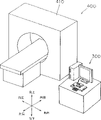
正如在图7和图8中所示,本实施例的控制装置200由图像显示设备300的一部分构成,并且与显示单元211一起被连接到主机212上。正如在图9和图10中显示的,本实施例的图像显示设备300作为断层X光摄影检查系统400的一部分被形成,并且被连接到CT扫描器410上。As shown in FIGS. 7 and 8 , the control device 200 of the present embodiment is constituted by a part of the
该实施例的图像显示设备300包括作为计算机主机的硬件的CPU301,并且该CPU301通过总线302连接到ROM303、RAM304、HDD(硬盘驱动器)305、FDD(FD驱动器)307、CD驱动器309、控制单元200、显示器211以及I/F单元311之类的硬件连接,其中FD(软盘)306可交换地装入FDD307中,而CD(密致盘)ROM308可交换地装入CD驱动器309中。The
CT扫描器410包括图像选择装置411,它是一种用于获取图像的装置;以及通讯装置412,它是一种图像提供装置;而且,图像选择装置411从人体上(图中未显示)拾取多个连续的断层扫描图像数据。按顺序从受检人身体中拾取的该多个图像数据帧作为序列数据被存储,而通信单元412将该数据传送到图像显示设备300。The
本发明的图像显示设备300中,硬件比如只ROM3,、RAM304、HDD305、可交换的FD306、以及可交换的CD-ROM308对应于信息存储媒体,而计算机程序或用于CPU301的资源是存储在这些零部件的至少一个中。该软件被提前安装在图像显示设备300中,然后在激活图像显示设备300的时候读到CPU301中。In the
以这种方式,CPU301读出一个适当的计算机程序并且执行各种处理,因此,本实施例的图像显示设备300逻辑上包括作为各种功能的各种装置,比如图像获取装置321,图像存储装置322,图像显示装置323,图像切换装置324,和图像选择装置325,正如图10所示。In this way, the CPU 301 reads out an appropriate computer program and executes various processes, therefore, the
图像获取装置321对应于这样的功能,即CPU301按照储存在RAM304中的计算机程序来识别I/F装置311的接收数据,因此,图像获取装置321从CT扫描器410中获得序列数据。图像存储装置322对应于在HDD305中构成的存储区域,以致于CPU301根据上面所述的计算机程序来识别该区域,而图像存储装置322因此储存通过图像获取装置321获得的序列数据。The image acquisition unit 321 corresponds to a function that the CPU 301 recognizes received data of the I/F unit 311 according to a computer program stored in the RAM 304 , and thus the image acquisition unit 321 acquires sequence data from the
图像显示装置323对应于这样功能,即CPU301使得HDD305的储存数据显示在显示装置211上,因此储存在图像存储装置322中的来自序列数据的图像数据的至少一帧被显示。该显示可以被控制为各种形式,但是本实施例的图像显示设备300采用将两组序列数据的图像数据的关联帧向左向右平行的显示作为它的基本形式,正如在图11中所示。Image display device 323 corresponds to a function that CPU 301 causes stored data of HDD 305 to be displayed on display device 211, whereby at least one frame of image data from sequence data stored in image storage device 322 is displayed. The display can be controlled in various forms, but the
下列描述对应于这样的功能,即CPU301识别控制装置200的控制信号并执行规定的数据处理,并且图像切换装置324按照控制单元200的操纵杆203的输入控制来切换由图像显示装置323显示的图像数据,如在图12中所示。The following description corresponds to the function that the CPU 301 recognizes the control signal of the control device 200 and performs prescribed data processing, and the image switching device 324 switches the image displayed by the image display device 323 in accordance with the input control of the joystick 203 of the control unit 200 data, as shown in Figure 12.
更具体地,将操纵杆203向右旋转将导致被显示的序列数据的图像数据的多个帧在向前方向按顺序地切换,而将操纵杆203向左旋转将导致反方向的顺序切换。这时,输入控制装置100按三个步骤来检测控制部件102向左右方向的旋转角度,正如先前描述的,该图像数据根据该旋转角度以三种速度而被切换。More specifically, turning the joystick 203 to the right will cause frames of image data of the displayed sequence data to sequentially switch in the forward direction, while turning the joystick 203 to the left will cause sequential switching in the reverse direction. At this time, the input control device 100 detects the rotation angle of the control member 102 in the left and right directions in three steps, and the image data is switched at three speeds according to the rotation angle as described earlier.
当操纵杆203向前倾斜时,被显示的序列数据的图像数据的多个帧在向前方向只被切换一帧,而当操纵杆203向后方倾斜时,显示图像数据在反方向被切换一帧。进一步,当图像数据的一对帧象先前描述的那样被显示时,设置默认值将两帧图像数据确立为处理的对象,而操纵杆203向左和右的旋转或操纵杆203向前或向后方向的倾斜因此导致两组序列数据的显示的图像数据以相同的速度切换,而不改变同步。When the joystick 203 is tilted forward, a plurality of frames of image data of the displayed sequence data is switched by only one frame in the forward direction, and when the joystick 203 is tilted backward, the displayed image data is switched by one frame in the reverse direction. frame. Further, when a pair of frames of image data is displayed as previously described, setting the default value establishes two frames of image data as the object of processing, and the rotation of the joystick 203 to the left and right or the joystick 203 forward or Tilting in the rear direction thus causes the displayed image data of the two sets of sequence data to switch at the same speed without changing the synchronization.
当一对图像数据帧象先前描述的那样被显示时,图像选择装置325根据控制装置200的操纵杆203的向左和向右倾斜来选择处理的对象。更具体地,当一对图像数据帧象先前描述的那样被显示时,该默认设置将这两个图像确立为处理对象,但是在该状态中操纵杆203向右倾斜将导致只选择右边的图像数据帧作为处理对象。然后,操纵杆203的旋转和操纵杆203向前向后倾斜将导致右边的图像数据帧被切换,而左边的图像数据帧不切换。When a pair of image data frames are displayed as previously described, the image selection means 325 selects an object to be processed according to the left and right tilts of the joystick 203 of the control means 200 . More specifically, when a pair of image data frames are displayed as previously described, the default setting establishes these two images as processing objects, but tilting the joystick 203 to the right in this state will cause only the right image to be selected Data frame as the processing object. Rotation of the joystick 203 and tilting of the joystick 203 forward and backward will then cause the right frame of image data to be switched and the left frame of image data not to be switched.
当右边的图像数据帧被选择时,只有操纵杆203的一种倾斜会导致其返回至初始状态,其中图像数据的两帧被选择为处理的对象,而当操纵杆203被再一次从起始状态倾斜到左边时,只有左边的图像数据帧被选择为处理对象。When the frame of image data on the right is selected, only one tilt of the joystick 203 will cause it to return to the initial state, wherein two frames of image data are selected as the object of processing, and when the joystick 203 is moved from the initial When the state is tilted to the left, only the image data frame on the left is selected as the processing object.
上述图像显示设备300的各种装置通过使用比如HDD305和I/F单元311等硬件来实现,但是这些装置的主要部份通过硬件CPU301根据存储在信息存储介质比如RAM304中的计算机程序的操作来实现。The various means of the
这类计算机程序以软件的形式被存储在一个信息存储介质比如RAM304上,以使CPU301执行处理,例如:一种处理,用于从在I/F装置311处接收来自CT扫描器410的序列数据;一种处理,用于在HDD305上存储接收的序列数据;一种处理,用于在显示器211上显示该储存的序列数据;一种处理,用于根据控制单元200的操纵杆203的向左或向右的旋转在向前或相反方向按顺序地切换显示的图像数据;一种处理,用于根据操纵杆203的向前或向后的倾斜在向前或相反方向一次一帧地切换该显示的图像数据;以及一种处理,用于当一对图像数据帧被显示时,根据操纵杆203的向右向左倾斜来选择处理对象。Such a computer program is stored in the form of software on an information storage medium such as RAM 304 to cause CPU 301 to execute processing, for example: a processing for receiving sequence data from
接下来依次描述上述结构的本实施例的断层X光摄影检查装置的断层X光摄影检查方法。多个断层X光摄影图像数据的帧首先从一个病人的身体(图中未显示)上通过CT扫描器410被提取,并且该多个图像数据帧作为序列数据被登记在图像显示设备中。Next, the tomographic inspection method of the tomographic inspection apparatus of the present embodiment with the above-mentioned structure will be described sequentially. A plurality of frames of tomographic image data are first extracted from a patient's body (not shown) through the
当序列数据已被登记在图像显示设备300中时,操作员(图中未显示)用控制装置200执行一个规定操作,以致序列数据的图像数据帧被显示在显示器211上。当从病人中拾取的并且登记在本实施例的图像显示设备300中数据例如包含使用了对比介质的序列数据和没有使用对比介质的序列数据时,用于相同的断层X光摄影位置的该两种序列数据的图像数据帧能在该显示屏幕的右边和左边并行地显示,正如图11所示。When the sequence data has been registered in the
虽然正如先前说明的那样被平行地显示在左右的图像数据的两个帧以相同的速度按照本实施例的图像显示设备的基本操作被同步地切换,作为该操作的一种应用,该两帧图像显示数据也可以被设置为不同切换速度。Although two frames of image data displayed in parallel on the left and right as explained earlier are switched synchronously at the same speed according to the basic operation of the image display device of this embodiment, as an application of this operation, the two frames Image display data can also be set to different switching speeds.
在这种情况下,正如在图13中所示,被并行地显示到左和右的一对图像数据帧的两个都被最初地设置为处理对象(步骤S2和S7--S8),但是,每当操作员将控制单元200的操纵杆203向左或右倾斜时,处理对象被切换并设置为左边的帧、右边的帧、或两个帧(步骤S3-S12)。In this case, as shown in FIG. 13, both of a pair of image data frames displayed to the left and right in parallel are initially set as processing objects (steps S2 and S7--S8), but , whenever the operator tilts the joystick 203 of the control unit 200 to the left or right, the processing object is switched and set to the left frame, the right frame, or both frames (steps S3-S12).
正如先前描述的,当操纵杆203被向前倾斜时,处理对象已被选择(步骤S13),被显示的处理对象的图像数据如图12所示仅仅向前地被切换一帧(步骤S14),而当操纵杆203被向后方倾斜时,该图像数据仅仅被反方向地切换一帧(步骤S15和S16)。As previously described, when the joystick 203 is tilted forward, the processing object has been selected (step S13), and the displayed image data of the processing object is switched forward by only one frame as shown in FIG. 12 (step S14) , and when the joystick 203 is tilted backward, the image data is only switched by one frame in the reverse direction (steps S15 and S16).
进一步,正如在图14中所示,当操纵杆203被向右旋转时,被显示的处理对象的图像数据根据旋转角度以高、中或低速在向前方向按顺序地切换(步骤S17--S22),而当操纵杆203被向左旋转时,图像数据以与旋转角度相应的速度在反方向上被切换(步骤S23--S28)。Further, as shown in FIG. 14, when the joystick 203 is rotated to the right, the displayed image data of the processing object is sequentially switched in the forward direction at a high, medium or low speed according to the rotation angle (step S17-- S22), and when the joystick 203 is rotated to the left, the image data is switched in the reverse direction at a speed corresponding to the rotation angle (steps S23-S28).
被显示的该对图像数据帧最初与病人身体的拾取位置同步,并且在该状态下当该两帧被安排为处理对象时,该两种形式的序列数据在向前或相反方向被同步地切换。The pair of image data frames that are displayed are initially synchronized with the pickup position of the patient's body, and when the two frames are arranged as processing objects in this state, the two forms of sequence data are switched synchronously in the forward or reverse direction .
然而,如果该对序列数据中只有一个作为处理对象在向前或反方向被切换,显示的该对图像数据帧中的病人身体向前或向后方向的位置将岔开。However, if only one of the pair of sequence data is switched as the processing object in the forward or reverse direction, the position of the patient's body in the forward or backward direction in the displayed pair of image data frames will diverge.
例如,如果在此种情况下操纵杆203被向下移动,未被选择的该帧图像数据中的病人身体的向前和向后方向的位置可以被设置与选择的图像数据帧中病人身体向前或向后方向的位置同步。For example, if the joystick 203 is moved downward in this case, the positions of the forward and backward directions of the patient's body in the unselected frame of image data can be set to be the same as those of the patient's body in the selected frame of image data. Position synchronization in forward or backward direction.
正如上文所述,本实施例的断层X光摄影检查装置400的图像显示设备300可以在显示器211显示通过CT扫描器410从病人身体中获取的多个序列断层X光摄影图像的图像数据,并且因为这些显示的图像数据可以在向前或反方向由操纵杆203的向前或向后倾斜切换,所以操作员希望观看的图像数据可以被正确地搜索。As mentioned above, the
另外,将操纵杆203向左向右的旋转能使被显示的图像数据能够在向前或反方向被顺序地切换,从而能迅速地搜索多帧序列图像数据。尤其是,该切换速度可以通过操纵杆203的旋转角度被控制,并且多帧序列图像数据因此可以被轻易地搜索。In addition, rotating the joystick 203 to the left or right can enable the displayed image data to be sequentially switched in the forward or reverse direction, so that the multi-frame sequential image data can be quickly searched. In particular, the switching speed can be controlled by the rotation angle of the joystick 203, and thus the multi-frame sequence image data can be easily searched.
进一步,一对关联的图像数据帧可以在显示器211上平行地显示,并且在这种情况下该对图像数据可以被同时且同步地切换,从而更容易地研究和比较两组序列数据。将操纵杆203向左向右倾斜允许选择将作为处理对象的图像数据,从而允许自由地观看该图像数据。Further, a pair of associated image data frames can be displayed in parallel on the display 211, and in this case the pair of image data can be switched simultaneously and synchronously, making it easier to study and compare two sets of sequence data. Tilting the joystick 203 left to right allows selection of image data to be processed, thereby allowing free viewing of the image data.
而且,在本实施例的控制装置200中,一旦手工操作被释放操纵杆自动地返回到它的初始位置,因而不需要人工将操纵杆203返回到初始位置。因此本实施例的断层X光摄影检查装置400通过简单控制能使从人体中获取的多个序列断层X光摄影图像数据被观看,更进一步,能改善断层X光摄影检查的可操纵性。Also, in the control device 200 of the present embodiment, the joystick automatically returns to its original position once the manual operation is released, so that it is not necessary to manually return the joystick 203 to the original position. Therefore, the
特别地,在本实施例的断层X光摄影检查系统400中,CT扫描器410、显示器211和操纵杆203的方向都一致,正如图9所示,因此操作员可以有效地识别病人身体、显示的图像和输入控制的相对方位。而且,在本实施例的控制装置200中,正如图3所示,在操纵杆203上端的向前和向后、向左向右倾斜方向的标示进一步改进该设备的可操纵性。In particular, in the
而且,在本实施例的控制装置200的输入控制装置100中,连接到操纵杆203的四向转换开关101被安装在第一个电路基板106上,而第一电路板106被安装在旋转部件107上;传感器元件116被安装在大尺寸的第二个电路板115上,而第二电路板115被安装在基础部件108上。用于检测操纵杆203向左向右和向前向后倾斜以及检测操纵杆203向左向右的装置因此可以由市场上销售包装部件来实现,因此输入控制装置100的结构简单,因此提高生产率。Also, in the input control device 100 of the control device 200 of the present embodiment, the four-way switch 101 connected to the joystick 203 is mounted on the first circuit board 106, and the first circuit board 106 is mounted on the rotating part 107 ; the sensor element 116 is mounted on a large-sized second circuit board 115 , and the second circuit board 115 is mounted on the base part 108 . The means for detecting the tilting of the joystick 203 to the left and right and forward and backward as well as detecting the tilting of the joystick 203 to the left and right can therefore be realized by the packaged parts sold on the market, so the structure of the input control device 100 is simple, thus improving the productivity .
虽然只有三个传感器元件116被安装在第二个电路板115上,通过结合这三个传感器元件116的检测结果按三个步骤来检测操纵杆203向左向右两个方向的旋转角度,因此用少量的零部件就可实现杰出的功能。Although only three sensor elements 116 are mounted on the second circuit board 115, by combining the detection results of these three sensor elements 116, the rotation angles of the joystick 203 in two directions, left and right, are detected in three steps, so Excellent functionality can be achieved with a small number of parts.
本发明不局限于上述的实施例,而是在本发明的范围内允许有各种修改。作为一个实例,虽然给出的情况是在上述实施例中通过CT扫描器410从一个病人身体提取断层X光摄影图像,但是该图像还可以通过MRI设备(图中未显示)而获得。另外,虽然给出的这种情况是在上述实施例中多个序列图像数据由病人身体的断层X光摄影图像构成,但是该序列数据也可以采取例如运动图像数据的形式。The present invention is not limited to the above-described embodiments, but various modifications are allowed within the scope of the present invention. As an example, although a case has been given in which tomographic images are taken from a patient's body by the
进一步,虽然给出的情况是在上述实施例中图像显示设备300在显示器211上平行地显示一对向左和向右的图像数据帧,明显地也可以只显示一个图像数据帧,或显示两个或更多图像数据帧,正如图15所示。Further, although it is given that the
进一步,虽然上述实施例中给出了这种情况,其中两组不同的序列数据的图像数据被并行地显示,但是,例如也可以显示一组序列数据中的不同的向前/向后位置的一对图像数据帧,或者显示经过不同的图像处理的单帧图像数据的多个图像。Further, although the above embodiment has given the case where the image data of two different sets of sequence data are displayed in parallel, but, for example, it is also possible to display images of different forward/backward positions in one set of sequence data A pair of frames of image data, or multiple images showing a single frame of image data with different image processing.
虽然在上述实施例中给出了这种情况,其中四向转换开关101被用作为输入控制装置100中的多向转换开关,但是该多向转换开关也可以为八向转换开关,或者一个多向传感器可以用于倾斜角度的模拟检测。Although this situation has been given in the above-mentioned embodiment, wherein the four-way changeover switch 101 is used as the multi-way changeover switch in the input control device 100, the multi-way changeover switch can also be an eight-way changeover switch, or a multi-way changeover switch. The orientation sensor can be used for analog detection of tilt angle.
虽然描述了这种情况,其中三个传感器元件116以三个步骤每15°地检测向左和向右的旋转角度,但是这些传感器元件116的数量、检测步骤的数量和检测角度可以按需要调整,并且可以用模拟传感器无级地检测该旋转角度。Although a case has been described in which three sensor elements 116 detect the leftward and rightward rotation angles every 15° in three steps, the number of these sensor elements 116, the number of detection steps, and the detection angle can be adjusted as needed , and this rotation angle can be detected steplessly with an analog sensor.
虽然在上述实施例中给出了这种情况,其中:通过操纵杆203的向前和向后倾斜来执行图像数据在向前或相反方向的单帧切换,通过操纵杆203向左和向右的旋转来执行图像数据在向前或相反方向的顺序切换,通过操纵杆203向左和向右的倾斜来选择处理对象,并且通过操纵杆203的向下位移来恢复多帧图像数据的向前或相反位置的同步,但是这些手工操作和图像控制的组合可以按照预先定义而进行各种各样的设定。Although the case has been given in the above-mentioned embodiment, wherein: the single-frame switching of the image data in the forward or reverse direction is performed by tilting the joystick 203 forward and backward, the left and right direction by the joystick 203 The rotation of the joystick 203 is used to perform sequential switching of the image data in the forward or reverse direction, the object to be processed is selected by tilting the joystick 203 to the left and right, and the forward movement of the multi-frame image data is restored by the downward displacement of the joystick 203 Or the synchronization of the opposite position, but the combination of these manual operations and image control can be set in various ways according to the pre-definition.
虽然在上述实施例中给出了这种情况,其中作为操纵操纵杆203的方法,向前和后的倾斜、向左和右的倾斜以及向左和右的旋转都是单独执行的,但是这些操作也可以被同时执行。在这种情况下,正如在图3中所示,向前向后向左向右方向的倾斜被显示在本实施例的控制装置200中操纵杆203的上端,并且当操纵杆203被旋转时,该旋转将不会使指示的倾斜方向与倾斜的实际方向脱离,并且因此有效地防止了操纵杆203的不正确操作。Although the case has been given in the above-described embodiment in which, as a method of manipulating the joystick 203, forward and backward tilting, leftward and rightward tilting, and leftward and rightward rotation are individually performed, these Operations can also be performed concurrently. In this case, as shown in FIG. 3 , the inclination of forward, backward, left, and right directions is displayed on the upper end of the joystick 203 in the control device 200 of the present embodiment, and when the joystick 203 is rotated , this rotation will not disengage the indicated direction of tilt from the actual direction of tilt, and thus effectively prevents incorrect operation of the joystick 203 .
另外,操纵杆203的旋转角度被限制向左和向右旋转的45°角,并且有效地防止了不正确操作。进一步,虽然在上述实施例中给出了这种情况,其中操纵杆203的旋转角度被限制到向左和向右旋转45度,但是该旋转角度可以增加或减少,或者该旋转角度可以一点都不被限制。In addition, the rotation angle of the joystick 203 is limited to the 45° angle of left and right rotation, and incorrect operation is effectively prevented. Further, although the case has been given in the above-described embodiment in which the rotation angle of the joystick 203 is limited to 45 degrees to the left and right, the rotation angle may be increased or decreased, or the rotation angle may not be changed at all. Not restricted.
最后,在前述的实施例中描述了这种情况,其中CPU301根据存储在比如RAM304中的计算机程序工作,作为结果,逻辑上实现了作为图像显示设备300的各种功能的各种装置。然而,这些不同装置中的每个都可以作为一个专用且具有特色的硬件单元来实现;或者一部份可以作为软件储存在,例如,RAM304中,而一部份可以作为硬件被形成。Finally, the case was described in the foregoing embodiment in which the CPU 301 operates according to a computer program stored in, for example, the RAM 304 , and as a result, various means as various functions of the
Claims (8)
Applications Claiming Priority (2)
| Application Number | Priority Date | Filing Date | Title |
|---|---|---|---|
| JP2001279889A JP2003084910A (en) | 2001-09-14 | 2001-09-14 | Input operation device and image display device |
| JP279889/2001 | 2001-09-14 |
Publications (1)
| Publication Number | Publication Date |
|---|---|
| CN1554043A true CN1554043A (en) | 2004-12-08 |
Family
ID=19103984
Family Applications (1)
| Application Number | Title | Priority Date | Filing Date |
|---|---|---|---|
| CNA028175271A Pending CN1554043A (en) | 2001-09-14 | 2002-09-13 | Input control device for accepting multiple input operations on a single control unit |
Country Status (6)
| Country | Link |
|---|---|
| US (1) | US7148880B2 (en) |
| EP (1) | EP1429236A4 (en) |
| JP (1) | JP2003084910A (en) |
| KR (1) | KR100586214B1 (en) |
| CN (1) | CN1554043A (en) |
| WO (1) | WO2003025733A1 (en) |
Cited By (1)
| Publication number | Priority date | Publication date | Assignee | Title |
|---|---|---|---|---|
| CN116627206A (en) * | 2023-06-28 | 2023-08-22 | 中国船舶重工集团公司第七0七研究所九江分部 | A modular watertight joystick |
Families Citing this family (33)
| Publication number | Priority date | Publication date | Assignee | Title |
|---|---|---|---|---|
| US20050140653A1 (en) * | 2003-12-04 | 2005-06-30 | Velimir Pletikosa | Character key incorporating navigation control |
| CN100485839C (en) * | 2004-03-12 | 2009-05-06 | 株式会社根本杏林堂 | Input operation device |
| NL1025722C2 (en) * | 2004-03-15 | 2005-09-16 | Univ Delft Tech | Joystick. |
| JP4475092B2 (en) * | 2004-10-20 | 2010-06-09 | パナソニック株式会社 | Electronic component midpoint return mechanism and input operation electronic component using the same |
| FR2877113B1 (en) * | 2004-10-22 | 2007-05-11 | Commissariat Energie Atomique | AUTONOMOUS DEVICE, SYSTEM AND METHOD FOR NAVIGATION IN A SPACE OF AT LEAST THREE DIMENSIONS. |
| US20060100979A1 (en) * | 2004-10-27 | 2006-05-11 | Eastman Kodak Company | Controller for a medical imaging system |
| TWI263879B (en) * | 2005-01-07 | 2006-10-11 | Transpacific Plasma Llc | Switching signal input device used for an electronic device |
| US7463920B2 (en) * | 2005-03-25 | 2008-12-09 | Siemens Medical Solutions Usa, Inc. | Rapid MR visualization of interventional devices |
| DE102005014198B3 (en) * | 2005-03-29 | 2006-09-21 | Preh Gmbh | Operating element for setting a heating, ventilation or air conditioning device of a motor vehicle |
| DE102005061848A1 (en) * | 2005-12-23 | 2007-06-28 | Siemens Ag | Method for navigating through medical image information |
| GB2434227B (en) * | 2005-12-27 | 2010-12-15 | Timothy Poston | Computer input device enabling three degrees of freedom and related input and feedback methods |
| KR100896055B1 (en) * | 2007-01-15 | 2009-05-07 | 엘지전자 주식회사 | Mobile terminal with rotary input device and display method thereof |
| JP5285863B2 (en) * | 2007-03-06 | 2013-09-11 | 任天堂株式会社 | Information selection device, information selection program, game device, and game program |
| CN101878464A (en) * | 2007-12-05 | 2010-11-03 | 奥克斯摩斯有限公司 | Data input device |
| TWI368157B (en) * | 2008-03-26 | 2012-07-11 | Elan Microelectronics Corp | Stress sensor and electronic device haveing the same |
| US8896620B2 (en) | 2009-03-04 | 2014-11-25 | Mayo Foundation For Medical Education And Research | Computer input device |
| JP5534574B2 (en) * | 2009-03-19 | 2014-07-02 | 独立行政法人国立がん研究センター | Bending operation device for insertion instrument |
| US9870021B2 (en) | 2009-04-15 | 2018-01-16 | SeeScan, Inc. | Magnetic manual user interface devices |
| JP5515511B2 (en) * | 2009-08-21 | 2014-06-11 | 富士ゼロックス株式会社 | Input device and information processing device |
| WO2011146668A2 (en) | 2010-05-18 | 2011-11-24 | Seektech, Inc. | User interface devices, apparatus, and methods |
| EP3179330B1 (en) | 2010-08-20 | 2020-03-18 | SeeScan, Inc. | Magnetic sensing user interface device |
| WO2012051357A1 (en) | 2010-10-12 | 2012-04-19 | Mark Olsson | Magnetic thumbstick user interface devices |
| EP2665989B1 (en) | 2010-11-08 | 2019-12-25 | SeeScan, Inc. | Slim profile magnetic user interface devices |
| EP3043231A1 (en) | 2010-12-02 | 2016-07-13 | SeeScan, Inc. | Magnetically sensed user interface devices |
| US9678577B1 (en) | 2011-08-20 | 2017-06-13 | SeeScan, Inc. | Magnetic sensing user interface device methods and apparatus using electromagnets and associated magnetic sensors |
| TWI479526B (en) * | 2012-08-22 | 2015-04-01 | Wistron Corp | Switch mechanism for activating different switches and portable electronic device therewith |
| FR3001439B1 (en) | 2013-01-29 | 2015-02-27 | Eurocopter France | CONTROL MEMBER HAVING A COLLECTIVE LEVER OF PALESTS AND A LACET CONTROL MEANS, AND AIRCRAFT |
| US9069396B2 (en) * | 2013-03-12 | 2015-06-30 | Lightlab Imaging, Inc. | Controller and user interface device, systems, and methods |
| EP2997453B1 (en) | 2013-05-17 | 2020-10-21 | SeeScan, Inc. | User interface devices |
| US10317926B2 (en) | 2016-02-25 | 2019-06-11 | Motorola Solutions, Inc. | Method and apparatus for controlling an electronic device using a rotary control |
| CN105892687B (en) * | 2016-05-04 | 2018-08-31 | 北京航空航天大学 | A kind of single-degree-of-freedom force feedback handle apparatus and its working method |
| JP7238813B2 (en) * | 2020-01-28 | 2023-03-14 | 株式会社島津製作所 | radiography equipment |
| US20220244078A1 (en) * | 2021-02-02 | 2022-08-04 | Cypress Semiconductor Corporation | Capacitive differential rotary encoder |
Family Cites Families (14)
| Publication number | Priority date | Publication date | Assignee | Title |
|---|---|---|---|---|
| JPS63262519A (en) | 1987-04-21 | 1988-10-28 | Matsushita Electric Ind Co Ltd | dial device |
| JPH05113849A (en) | 1991-10-23 | 1993-05-07 | Canon Inc | Input device |
| JPH05232917A (en) * | 1992-02-21 | 1993-09-10 | Toshiba Corp | Image display device |
| US5589828A (en) * | 1992-03-05 | 1996-12-31 | Armstrong; Brad A. | 6 Degrees of freedom controller with capability of tactile feedback |
| JPH05282374A (en) * | 1992-04-02 | 1993-10-29 | Sony Corp | Still picture display device |
| JP3229682B2 (en) * | 1992-12-22 | 2001-11-19 | 株式会社ソニー・コンピュータエンタテインメント | Information input device |
| JPH07168690A (en) * | 1993-12-14 | 1995-07-04 | Hitachi Medical Corp | Updating and displaying method for image |
| JP3639030B2 (en) * | 1995-02-28 | 2005-04-13 | 株式会社東芝 | Image display system and image display method using the system |
| KR100501145B1 (en) * | 1996-03-05 | 2005-07-18 | 가부시키가이샤 세가 | Manipulation controller and electronic device using the same |
| JPH10214128A (en) * | 1997-01-30 | 1998-08-11 | Yazaki Corp | Joystick type multi-function controller |
| US5911627A (en) * | 1997-10-23 | 1999-06-15 | Logitech, Inc. | Electromagnetic joystick using varying overlap of coils and conductive elements |
| JP4452854B2 (en) | 1999-08-03 | 2010-04-21 | 株式会社アマダ | Shearing method and shearing machine |
| JP2001105754A (en) | 1999-10-07 | 2001-04-17 | Fuji Photo Film Co Ltd | Original plate for lithographic printing |
| US20020196232A1 (en) * | 2001-06-22 | 2002-12-26 | Chih-Feng Chen | Input device with two elastic fulcrums for six degrees of freedom data input |
-
2001
- 2001-09-14 JP JP2001279889A patent/JP2003084910A/en active Pending
-
2002
- 2002-09-13 CN CNA028175271A patent/CN1554043A/en active Pending
- 2002-09-13 EP EP02798840A patent/EP1429236A4/en not_active Withdrawn
- 2002-09-13 US US10/476,179 patent/US7148880B2/en not_active Expired - Fee Related
- 2002-09-13 KR KR1020037014293A patent/KR100586214B1/en not_active Expired - Fee Related
- 2002-09-13 WO PCT/JP2002/009449 patent/WO2003025733A1/en not_active Ceased
Cited By (1)
| Publication number | Priority date | Publication date | Assignee | Title |
|---|---|---|---|---|
| CN116627206A (en) * | 2023-06-28 | 2023-08-22 | 中国船舶重工集团公司第七0七研究所九江分部 | A modular watertight joystick |
Also Published As
| Publication number | Publication date |
|---|---|
| US7148880B2 (en) | 2006-12-12 |
| EP1429236A1 (en) | 2004-06-16 |
| JP2003084910A (en) | 2003-03-20 |
| KR20030093340A (en) | 2003-12-06 |
| KR100586214B1 (en) | 2006-06-07 |
| EP1429236A4 (en) | 2009-02-25 |
| US20040130529A1 (en) | 2004-07-08 |
| WO2003025733A1 (en) | 2003-03-27 |
Similar Documents
| Publication | Publication Date | Title |
|---|---|---|
| CN1554043A (en) | Input control device for accepting multiple input operations on a single control unit | |
| US7123292B1 (en) | Mosaicing images with an offset lens | |
| CN1217255C (en) | Electronic device with dispaly function | |
| CN1991711A (en) | Portable device having rotatable input buttons and method of operating the same | |
| CN1813633A (en) | C-arm holding device and X-ray diagnostic device | |
| US7995704B2 (en) | Panoramic x-ray photographing apparatus and method for photographing using the same | |
| CN111432729B (en) | X-ray CT shooting device | |
| JP2002301065A (en) | Medical tomographic image display | |
| EP3510930A2 (en) | Automated and configurable magnification stand | |
| JP3780891B2 (en) | X-ray fluoroscopic equipment | |
| JP4561981B2 (en) | X-ray CT system | |
| JP2009192384A (en) | Tomography equipment | |
| JP4653041B2 (en) | System and method for synthesizing image blocks and creating a seamless enlarged image of a microscope slide | |
| CN112055562A (en) | X-ray CT imaging device and control method of X-ray CT imaging device | |
| EP4049591A1 (en) | Image processing device, imaging control device, radiography system, image processing method, and image processing program | |
| JP4665696B2 (en) | X-ray inspection equipment | |
| JP4299307B2 (en) | Non-tilt joystick with CCD detector | |
| JP2004245685A (en) | X-ray micro tomography system | |
| JP2019056855A (en) | Microscope system, display control method and display control program | |
| JP6307868B2 (en) | IMAGING DEVICE AND IMAGING DEVICE CONTROL METHOD | |
| CN1628610A (en) | Radiographic apparatus | |
| JP4687362B2 (en) | X-ray inspection equipment | |
| JPH0161193B2 (en) | ||
| JP7378376B2 (en) | Display device and control program | |
| JP7363543B2 (en) | Image diagnostic equipment |
Legal Events
| Date | Code | Title | Description |
|---|---|---|---|
| C06 | Publication | ||
| PB01 | Publication | ||
| C10 | Entry into substantive examination | ||
| SE01 | Entry into force of request for substantive examination | ||
| C02 | Deemed withdrawal of patent application after publication (patent law 2001) | ||
| WD01 | Invention patent application deemed withdrawn after publication |
Open date: 20041208 |