CN1554112A - wafer transfer equipment - Google Patents
wafer transfer equipment Download PDFInfo
- Publication number
- CN1554112A CN1554112A CNA028176804A CN02817680A CN1554112A CN 1554112 A CN1554112 A CN 1554112A CN A028176804 A CNA028176804 A CN A028176804A CN 02817680 A CN02817680 A CN 02817680A CN 1554112 A CN1554112 A CN 1554112A
- Authority
- CN
- China
- Prior art keywords
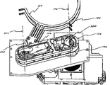
- arm
- load lock
- cam
- robotic arm
- link
- Prior art date
- Legal status (The legal status is an assumption and is not a legal conclusion. Google has not performed a legal analysis and makes no representation as to the accuracy of the status listed.)
- Granted
Links
Images







Classifications
-
- B—PERFORMING OPERATIONS; TRANSPORTING
- B25—HAND TOOLS; PORTABLE POWER-DRIVEN TOOLS; MANIPULATORS
- B25J—MANIPULATORS; CHAMBERS PROVIDED WITH MANIPULATION DEVICES
- B25J9/00—Program-controlled manipulators
- B25J9/02—Program-controlled manipulators characterised by movement of the arms, e.g. cartesian coordinate type
- B25J9/04—Program-controlled manipulators characterised by movement of the arms, e.g. cartesian coordinate type by rotating at least one arm, excluding the head movement itself, e.g. cylindrical coordinate type or polar coordinate type
- B25J9/041—Cylindrical coordinate type
- B25J9/042—Cylindrical coordinate type comprising an articulated arm
-
- H—ELECTRICITY
- H10—SEMICONDUCTOR DEVICES; ELECTRIC SOLID-STATE DEVICES NOT OTHERWISE PROVIDED FOR
- H10P—GENERIC PROCESSES OR APPARATUS FOR THE MANUFACTURE OR TREATMENT OF DEVICES COVERED BY CLASS H10
- H10P72/00—Handling or holding of wafers, substrates or devices during manufacture or treatment thereof
- H10P72/50—Handling or holding of wafers, substrates or devices during manufacture or treatment thereof for positioning, orientation or alignment
-
- B—PERFORMING OPERATIONS; TRANSPORTING
- B25—HAND TOOLS; PORTABLE POWER-DRIVEN TOOLS; MANIPULATORS
- B25J—MANIPULATORS; CHAMBERS PROVIDED WITH MANIPULATION DEVICES
- B25J9/00—Program-controlled manipulators
- B25J9/0093—Program-controlled manipulators co-operating with conveyor means
-
- H—ELECTRICITY
- H10—SEMICONDUCTOR DEVICES; ELECTRIC SOLID-STATE DEVICES NOT OTHERWISE PROVIDED FOR
- H10P—GENERIC PROCESSES OR APPARATUS FOR THE MANUFACTURE OR TREATMENT OF DEVICES COVERED BY CLASS H10
- H10P72/00—Handling or holding of wafers, substrates or devices during manufacture or treatment thereof
- H10P72/04—Apparatus for manufacture or treatment
- H10P72/0451—Apparatus for manufacturing or treating in a plurality of work-stations
- H10P72/0462—Apparatus for manufacturing or treating in a plurality of work-stations characterised by the construction of the processing chambers, e.g. modular processing chambers
-
- H—ELECTRICITY
- H10—SEMICONDUCTOR DEVICES; ELECTRIC SOLID-STATE DEVICES NOT OTHERWISE PROVIDED FOR
- H10P—GENERIC PROCESSES OR APPARATUS FOR THE MANUFACTURE OR TREATMENT OF DEVICES COVERED BY CLASS H10
- H10P72/00—Handling or holding of wafers, substrates or devices during manufacture or treatment thereof
- H10P72/04—Apparatus for manufacture or treatment
- H10P72/0451—Apparatus for manufacturing or treating in a plurality of work-stations
- H10P72/0466—Apparatus for manufacturing or treating in a plurality of work-stations characterised by the construction of the load-lock chamber
-
- H—ELECTRICITY
- H10—SEMICONDUCTOR DEVICES; ELECTRIC SOLID-STATE DEVICES NOT OTHERWISE PROVIDED FOR
- H10P—GENERIC PROCESSES OR APPARATUS FOR THE MANUFACTURE OR TREATMENT OF DEVICES COVERED BY CLASS H10
- H10P72/00—Handling or holding of wafers, substrates or devices during manufacture or treatment thereof
- H10P72/30—Handling or holding of wafers, substrates or devices during manufacture or treatment thereof for conveying, e.g. between different workstations
- H10P72/33—Handling or holding of wafers, substrates or devices during manufacture or treatment thereof for conveying, e.g. between different workstations into and out of processing chamber
- H10P72/3302—Mechanical parts of transfer devices
-
- H—ELECTRICITY
- H10—SEMICONDUCTOR DEVICES; ELECTRIC SOLID-STATE DEVICES NOT OTHERWISE PROVIDED FOR
- H10P—GENERIC PROCESSES OR APPARATUS FOR THE MANUFACTURE OR TREATMENT OF DEVICES COVERED BY CLASS H10
- H10P72/00—Handling or holding of wafers, substrates or devices during manufacture or treatment thereof
- H10P72/30—Handling or holding of wafers, substrates or devices during manufacture or treatment thereof for conveying, e.g. between different workstations
- H10P72/33—Handling or holding of wafers, substrates or devices during manufacture or treatment thereof for conveying, e.g. between different workstations into and out of processing chamber
- H10P72/3304—Handling or holding of wafers, substrates or devices during manufacture or treatment thereof for conveying, e.g. between different workstations into and out of processing chamber characterised by movements or sequence of movements of transfer devices
-
- H—ELECTRICITY
- H10—SEMICONDUCTOR DEVICES; ELECTRIC SOLID-STATE DEVICES NOT OTHERWISE PROVIDED FOR
- H10P—GENERIC PROCESSES OR APPARATUS FOR THE MANUFACTURE OR TREATMENT OF DEVICES COVERED BY CLASS H10
- H10P72/00—Handling or holding of wafers, substrates or devices during manufacture or treatment thereof
- H10P72/30—Handling or holding of wafers, substrates or devices during manufacture or treatment thereof for conveying, e.g. between different workstations
- H10P72/33—Handling or holding of wafers, substrates or devices during manufacture or treatment thereof for conveying, e.g. between different workstations into and out of processing chamber
- H10P72/3306—Horizontal transfer of a single workpiece
-
- Y—GENERAL TAGGING OF NEW TECHNOLOGICAL DEVELOPMENTS; GENERAL TAGGING OF CROSS-SECTIONAL TECHNOLOGIES SPANNING OVER SEVERAL SECTIONS OF THE IPC; TECHNICAL SUBJECTS COVERED BY FORMER USPC CROSS-REFERENCE ART COLLECTIONS [XRACs] AND DIGESTS
- Y10—TECHNICAL SUBJECTS COVERED BY FORMER USPC
- Y10S—TECHNICAL SUBJECTS COVERED BY FORMER USPC CROSS-REFERENCE ART COLLECTIONS [XRACs] AND DIGESTS
- Y10S414/00—Material or article handling
- Y10S414/135—Associated with semiconductor wafer handling
- Y10S414/139—Associated with semiconductor wafer handling including wafer charging or discharging means for vacuum chamber
Landscapes
- Engineering & Computer Science (AREA)
- Robotics (AREA)
- Mechanical Engineering (AREA)
- Container, Conveyance, Adherence, Positioning, Of Wafer (AREA)
Abstract
一种负载锁定室组件,包括负载锁定室、可拆卸地固定到该负载锁定室上的子室以及在子室内的具有初级枢轴的第一自动臂,其中第一自动臂可将衬底从大致负载锁定室中心的位置移动到负载锁定室外部的位置。
A load-locking chamber assembly includes a load-locking chamber, a sub-chamber detachably attached to the load-locking chamber, and a first automated arm with a primary pivot within the sub-chamber, wherein the first automated arm can move a substrate from a location approximately at the center of the load-locking chamber to a location outside the load-locking chamber.
Description
发明领域field of invention
本发明涉及一种真空传送设备,特别涉及一种用于在两个具有不同压力的区域之间传送衬底而且基本上不会影响每个区域的压力的工艺和设备。The present invention relates to vacuum transfer equipment, and more particularly to a process and apparatus for transferring a substrate between two zones having different pressures without substantially affecting the pressure in each zone.
发明背景Background of the invention
半导体刻蚀、清洗和淀积工艺通常采用希望在减压下例如在被排气(真空)室中进行的等离子体中间工艺。保持室内的压力在特殊预定范围内是非常重要的,以便避免半导体晶片制造工艺中的昂贵延迟和使制造的半导体晶片产品的质量的不希望的变化最小化。保持压力在预定范围内是很困难的,因为在器件制造期间,在连续或批量处理中从在大气条件下工作的外部源向处理室中连续地馈送衬底。为输送到处理室内的每个衬底或批量衬底控制和校准室压力所需要的时间大大增加了处理时间。由于控制和重新校准压力导致的产量减小提高了总器件成本。Semiconductor etch, clean and deposit processes typically employ plasma intermediate processes that are desirably performed under reduced pressure, such as in an evacuated (vacuum) chamber. It is very important to maintain the pressure within the chamber within a particular predetermined range in order to avoid costly delays in the semiconductor wafer fabrication process and to minimize undesired variations in the quality of the fabricated semiconductor wafer product. Maintaining the pressure within a predetermined range is difficult because substrates are continuously fed into the process chamber in continuous or batch processing from an external source operating at atmospheric conditions during device fabrication. The time required to control and calibrate the chamber pressure for each substrate or batch of substrates delivered to the chamber adds significantly to processing time. Yield reduction due to control and recalibration stress increases overall device cost.
室辅助操作时间(overhead time)定义为涉及处理室的任何操作但不包括实际晶片处理时间所需要的时间。处理室辅助操作时间通常包括在交换每个晶片之后用于将处理室内的压力减小到所希望的处理压力,将晶片加热到预定温度,给处理室排气以便允许交换晶片和晶片本身交换的时间周期。使辅助操作时间最小将会提高生产率和降低总器件成本。Chamber overhead time is defined as the time required for any operation involving the chamber but excluding actual wafer processing time. Chamber auxiliary operation time typically includes time spent after each wafer is exchanged to reduce the pressure within the chamber to the desired process pressure, heat the wafers to a predetermined temperature, and vent the chamber to allow for swapping of wafers and swapping of the wafers themselves. Time period. Minimizing auxiliary operation time will increase productivity and reduce overall device cost.
用于将半导体晶片送进或送出用于连续处理的处理室同时不破坏或影响室压力的设备和方法有很多。很多这种装置教导人们在与处理室的可操作连通中使用气锁室,即负载锁定室。这种负载锁定室可以被调整以匹配处理室内的工作压力,由此允许将衬底送进或送出处理室同时还允许处理室保持相对恒定的压力。在这些器件中,自动装置一般用做单臂,它的行程以基本线性方式移动晶片。该单臂传送路径构成为使得晶片的中心轴在中心自动臂枢轴上或附近通过。这种枢轴通常安装在负载锁定室的中心,因为物理尺寸受到自动连杆臂设计和相关的连杆臂行程的限制。结果是,这些类型的传送机构具有在负载锁定室组件中的过量内部室体积,这是由于传送机构所需要的传送臂路径。而且,由于连杆臂的初级或第一枢轴位于负载锁定室内的中心,因此维修和接触该设备是很困难的。而且,现有技术通常采用连接到步进电机驱动输出轴的定时传送带和滑轮装置以及连接到第一连杆臂轴的套筒的复杂系统,以便实现臂的旋转。Apparatus and methods for moving semiconductor wafers into and out of a processing chamber for continuous processing without disrupting or affecting the chamber pressure are numerous. Many of these arrangements teach the use of an air lock, ie load lock, in operable communication with the process chamber. Such a load lock chamber can be adjusted to match the operating pressure within the process chamber, thereby allowing substrates to be transported into and out of the process chamber while still allowing the process chamber to maintain a relatively constant pressure. In these devices, the robot is generally used as a single arm whose stroke moves the wafer in a substantially linear fashion. The single-arm transport path is configured such that the central axis of the wafer passes on or near the central robotic arm pivot. This pivot is usually mounted in the center of the load lock chamber as physical size is limited by the automatic linkage arm design and associated linkage arm travel. As a result, these types of transfer mechanisms have excess internal chamber volume in the load lock chamber assembly due to the transfer arm path required by the transfer mechanism. Also, because the primary or first pivot of the linkage arm is centrally located within the load lock chamber, servicing and accessing the device is difficult. Also, the prior art typically employs a complex system of timed belt and pulley arrangements connected to the stepper motor drive output shaft and a sleeve connected to the first link arm shaft in order to effectuate the rotation of the arm.
例如,授予Richards的美国专利US4584045公开了在晶片定位传送设备中使用传送带驱动。通过在传送机构的臂之一中使用弹簧存在问题。由于传送带磨损或伸长,弹簧延长臂以保持传送带拉紧。这改变了半导体晶片在室中的位置。晶片定位装置在该装置操作的所有阶段都必须是非常精确定位的。改变了定位的这种磨损是不希望的。For example, US Patent No. 4,584,045 to Richards discloses the use of a conveyor belt drive in a wafer alignment transfer apparatus. There is a problem with using a spring in one of the arms of the transfer mechanism. As the belt wears or elongates, the spring extends the arm to keep the belt taut. This changes the position of the semiconductor wafer in the chamber. Wafer positioning devices must be very precisely positioned at all stages of operation of the device. Such wear which alters the orientation is undesirable.
在授予Lada的美国专利US4728252中,公开了一种复杂晶片传送机构。这篇专利的装置具有在另一轴内密封的一个轴,该轴独立于外轴旋转。复杂的密封机构固有地将该装置暴露于潜在的故障和损坏。而且,该装置采用传送带并需要两个电机和两个电机控制电路,具有附加的导线系统等。这种装置的复杂性使其昂贵。而且,使用传送带将增加损坏或磨损的潜在性,产生污染。此外,随着传送带磨损或伸长,必须在规则基础上替换它们,这都是为了保持该装置的工作精度以及保持该设备内的污染颗粒的数量减少。替换传送带将产生用于该系统的附加维修成本和不希望的减少的时间。In US Pat. No. 4,728,252 to Lada, a complex wafer transfer mechanism is disclosed. The device of this patent has one shaft sealed within another shaft which rotates independently of the outer shaft. Complex sealing mechanisms inherently expose the device to potential failure and damage. Also, the device uses a conveyor belt and requires two motors and two motor control circuits, with additional wiring systems, etc. The complexity of such devices makes them expensive. Also, the use of conveyor belts increases the potential for damage or wear, creating contamination. Furthermore, as conveyor belts wear or elongate, they must be replaced on a regular basis, both to maintain the working accuracy of the device and to keep the number of contaminating particles within the equipment down. Replacing the conveyor belt would incur additional maintenance costs and undesirably reduced time for the system.
发明内容Contents of the invention
一种用于在具有不同压力的两个区域之间传送衬底晶片同时基本上不影响每个区域的压力的传送设备和工艺包括连接到处理室的负载锁定室组件。该负载锁定室组件包括负载锁定室和与该负载锁定室连通的子室。负载锁定室连接到处理室并包括在其间的可封闭端口。A transfer apparatus and process for transferring a substrate wafer between two regions having different pressures without substantially affecting the pressure of each region includes a load lock chamber assembly coupled to a processing chamber. The load lock chamber assembly includes a load lock chamber and a subchamber in communication with the load lock chamber. A load lock chamber is connected to the process chamber and includes a closable port therebetween.
子室包括具有在子室内的初级枢轴的第一自动臂,其中第一自动臂可以将衬底从负载锁定室的大致中心的位置移动到负载锁定室外部的位置。The subchamber includes a first robotic arm having a primary pivot within the subchamber, wherein the first robotic arm can move the substrate from a position approximately central to the load lock chamber to a position outside the load lock chamber.
第一自动臂包括第一端效应器,用于在两个区域之间传送衬底期间保持衬底。The first robotic arm includes a first end effector for holding the substrate during transfer of the substrate between the two regions.
第一自动臂安装在可旋转轴套上并包括第一连杆臂,第一连杆臂包括具有第一端和第二端的细长外壳,其中第一连杆臂包括设置在外壳内的第一凸轮和被第一凸轮驱动的第一四杆连杆机构。第一凸轮牢固地连接到同轴地安装在轴套内的轴上,其中该轴限定了自动臂的初级枢轴。第一自动臂还包括可旋转地连接到第一连杆臂的第二端并具有固定到转换臂的一端的第一端效应器的第一转换臂,其中第一连杆臂围绕轴的旋转使第一四杆连杆机构与第一凸轮配合并围绕次级枢轴旋转地移动第一转换臂。连杆臂和转换臂在子室内完全配合。The first robotic arm is mounted on a rotatable hub and includes a first linkage arm including an elongated housing having a first end and a second end, wherein the first linkage arm includes a first linkage arm disposed within the housing. A cam and a first four-bar linkage driven by the first cam. The first cam is rigidly connected to a shaft coaxially mounted within the bushing, wherein the shaft defines the primary pivot of the robotic arm. The first robotic arm also includes a first transition arm rotatably connected to a second end of the first linkage arm and having a first end effector fixed to one end of the transition arm, wherein the rotation of the first linkage arm about the axis Cooperating the first four-bar linkage with the first cam and rotationally moving the first transition arm about the secondary pivot. The linkage arm and transition arm fit perfectly within the subchamber.
第一四杆连杆机构包括连接到第一凸轮的第一凸轮跟随器、连接到第一凸轮跟随器的第一驱动器连杆以及连接到第一驱动器连杆和第一连杆臂的第一摇臂连杆。第一摇臂连杆包括摇臂和弹簧,其中弹簧连接到第一连杆臂的外壳和摇臂,并且摇臂可调地连接到该驱动器连杆。The first four-bar linkage mechanism includes a first cam follower connected to the first cam, a first driver link connected to the first cam follower, and a first driver link connected to the first driver link and the first link arm. Rocker linkage. The first rocker link includes a rocker arm and a spring, wherein the spring is connected to the housing of the first link arm and the rocker arm, and the rocker arm is adjustably connected to the driver link.
在优选实施例中,负载锁定室组件包括围绕初级枢轴可旋转的第二自动臂。第一和第二自动臂可彼此独立地旋转并且能将一个衬底放进处理室,同时从处理室取出另一衬底。第一和第二自动臂在子室内完全配合。In a preferred embodiment, the load lock chamber assembly includes a second robotic arm rotatable about a primary pivot. The first and second robotic arms are rotatable independently of each other and are capable of placing one substrate into the chamber while removing another substrate from the chamber. The first and second robotic arms fit perfectly within the subchamber.
负载锁定室组件还包括用于沿着初级枢轴垂直地移动第一和第二臂的第一电机、用于围绕初级枢轴旋转第一自动臂的第二电机和用于围绕初级枢轴旋转第二自动臂的第三电机。The load lock chamber assembly also includes a first motor for vertically moving the first and second arms along the primary pivot, a second motor for rotating the first robotic arm about the primary pivot, and a second motor for rotating the first robotic arm about the primary pivot. The third motor of the second automatic arm.
用于在具有不同压力的区域之间传送衬底而基本上不影响每个区域的压力的工艺包括:在连接到负载锁定室的可拆卸子室内安装第一和第二自动臂。第一和第二臂包括在子室内的初级枢轴。有源晶片在预定工作压力的处理室中被处理,其中处理室连接到负载锁定室并包括可封闭端口。利用第一自动臂将有源晶片从处理室取出,并且利用第二自动臂在处理室的工作压力下将第一排晶片设置在处理室中。端口封闭并且在工作压力下在处理室中处理第一排晶片,同时负载锁定室被排气,用于从负载锁定室外部接收第二排晶片。然后将负载锁定室内的压力减小到工作压力并且端口打开。利用第一自动臂从处理室取出第一排晶片(正在处理的),利用第二自动臂将第二排晶片设置到处理室中。A process for transferring a substrate between regions having different pressures without substantially affecting the pressure of each region includes mounting first and second robotic arms in a removable subchamber connected to the load lock chamber. The first and second arms include primary pivots within the subchambers. The active wafer is processed in a process chamber at a predetermined operating pressure, wherein the process chamber is connected to the load lock chamber and includes a closable port. Active wafers are removed from the processing chamber by a first robotic arm and a first row of wafers is placed in the processing chamber by a second robotic arm at an operating pressure of the processing chamber. The ports are closed and a first row of wafers is processed in the process chamber at operating pressure while the load lock is vented for receiving a second row of wafers from outside the load lock. The pressure in the load lock chamber is then reduced to working pressure and the port is opened. A first row of wafers (being processed) is removed from the chamber by a first robotic arm and a second row of wafers is placed into the chamber by a second robotic arm.
应该明白前面一般性的说明和下面的详细说明都是示意性的,趋于提供所要求保护的本发明的进一步解释。It is to be understood that both the foregoing general description and the following detailed description are exemplary and are intended to provide further explanation of the invention as claimed.
附图简述Brief description of the drawings
附图提供本发明的进一步理解并结合在本说明书中构成本说明书的一部分,并与文字说明一起表示本发明的实施例,以便解释本发明的原理。The accompanying drawings are included to provide a further understanding of the invention and are incorporated in and constitute a part of this specification, and together with the description, illustrate embodiments of the invention and serve to explain the principle of the invention.
附图中:In the attached picture:
图1A,图1B和图2表示包括负载锁定室和处理室的晶片传送设备的透视图。1A, 1B and 2 show perspective views of a wafer transfer apparatus including a load lock chamber and a process chamber.
图3表示负载锁定室和处理室的顶部平面图。Figure 3 shows a top plan view of the load lock chamber and process chamber.
图4表示负载锁定室和处理室的横截面图。Figure 4 shows a cross-sectional view of the load lock chamber and process chamber.
图5表示负载锁定室和处理室的侧向剖面图。Figure 5 shows a side sectional view of the load lock chamber and process chamber.
图6(a,b)表示晶片传送设备的部分透视图。Figure 6(a,b) shows a partial perspective view of a wafer transfer apparatus.
图7表示上连杆臂和上转换臂的部分分解透视图。Figure 7 shows a partially exploded perspective view of the upper link arm and upper transition arm.
图8表示上连杆臂的顶部平面图。Figure 8 shows a top plan view of the upper link arm.
图9、图10A、10B和图11表示上和下连杆臂组件的剖面图。9, 10A, 10B and 11 show cross-sectional views of the upper and lower link arm assemblies.
图12表示电机驱动组件的透视图。Figure 12 shows a perspective view of the motor drive assembly.
图13-图28逐级表示用于从负载锁定室组件将晶片送进和送出处理室的工艺的透视图。13-28 show step-by-step perspective views of the process for moving wafers into and out of the process chamber from the load lock chamber assembly.
优选实施例的详细说明Detailed Description of the Preferred Embodiment
下面介绍在真空下用于将晶片换进和换出处理室的设备和方法。该设备一般包括与处理室可操作连通的负载锁定室。负载锁定室和处理室之间的可操作连通允许在这两个室之间交换晶片,而不会升高处理室内的压力。在真空处理室中处理有源晶片时,例如等离子体中间处理,负载锁定室被排气到大气压,以便允许其它晶片排列好并装载到负载锁定室中。一旦排列好的晶片装载到负载锁定室中,负载锁定室压力减小到处理室的工作压力。在处理室中完成有源晶片的处理之后,取出有源晶片并与负载锁定室中排列好的晶片交换。然后在处理室中相应地处理排列好的晶片,先前处理过的有源晶片从负载锁定室中取出并与待处理其它晶片交换。必要时可重复这种循环。Apparatus and methods for changing wafers into and out of a process chamber under vacuum are described below. The apparatus generally includes a load lock chamber in operable communication with the processing chamber. Operable communication between the load lock chamber and the process chamber allows wafers to be exchanged between the two chambers without increasing the pressure within the process chamber. When active wafers are processed in a vacuum processing chamber, such as plasma intermediate processing, the load lock chamber is vented to atmospheric pressure to allow other wafers to be lined up and loaded into the load lock chamber. Once the aligned wafers are loaded into the load lock, the load lock pressure is reduced to the process chamber operating pressure. After the processing of the active wafers in the processing chamber is complete, the active wafers are removed and exchanged with the wafers that are aligned in the load lock chamber. The aligned wafers are then processed accordingly in the process chamber, and the previously processed active wafers are removed from the load lock chamber and exchanged with other wafers to be processed. This cycle can be repeated as necessary.
有利地,由于处理室的工作压力连续保持,因此实现了提高的产量。例如,光刻胶剥离工艺、刻蚀后残余物去除和各向同性刻蚀工艺通常要求处理室被抽真空到约1托到约10托的压力范围。在处理室内恒定地保持该工作压力提高了工具的制造性和处理一致性。在将晶片从具有预定压力范围的负载锁定室送进和送出处理室时,不再需要用于处理室的泵送和通气步骤,由此提高晶片的产量。通过这种方式,负载锁定室双重地用做传送室和负载锁定室。Advantageously, increased throughput is achieved due to the continuous maintenance of the operating pressure of the processing chamber. For example, photoresist stripping processes, post-etch residue removal, and isotropic etch processes typically require the process chamber to be evacuated to a pressure range of about 1 Torr to about 10 Torr. Maintaining this working pressure constantly within the processing chamber improves tool manufacturability and processing consistency. Pumping and venting steps for the processing chamber are eliminated when transferring wafers into and out of the processing chamber from a load lock chamber having a predetermined pressure range, thereby increasing wafer throughput. In this way, the load lock chamber doubles as a transfer chamber and a load lock chamber.
下面将参照附图详细介绍本发明的最佳实施例,本发明的例子示于附图中。DETAILED DESCRIPTION OF THE PREFERRED EMBODIMENTS Preferred embodiments of the present invention will be described in detail below with reference to the accompanying drawings, examples of which are shown.
图1和2表示设备100的透视图,它包括负载锁定室组件102和处理室104。设备100不限于所示的特殊结构。鉴于本公开的其它变化和结构对于本领域普通技术人员来说是显而易见的。如从这些附图所看到的,设备100安装在可移动小车106上,可移动小车106包括排气系统108和与负载锁定室组件102连通的真空泵系统110。1 and 2 show perspective views of an apparatus 100 including a load
图3示出了负载锁定室组件102和处理室104的顶部平面图。负载锁定室组件102和处理室104互连,其中可封闭的真空密封开口114设置和构成为用于允许晶片在两个室之间交换。如图所示,开口114构成为用于允许单晶片通过它。或者,开口114的大小和结构允许两个晶片同时通过,例如从处理室出来的被处理晶片和进入处理室的未处理晶片。负载锁定室组件102一般包括可拆卸子室116和室118。子室116可拆卸地固定于室118的壁上,并含有双端效应器晶片传送机构。如下面进一步的说明,双端效应器传送机构可自动地将晶片通过开口114送入和送出室118和104。由于接合臂位于固定于负载锁定室118的可拆卸子室116中,因此简化了自动臂的安装和维修。FIG. 3 shows a top plan view of the load
双端效应器晶片传送机构包括共享公共枢轴140的上连杆臂120和下连杆臂130,这些连杆臂围绕该枢轴140接合。上连杆臂120的末端可旋转地连接到上转换臂122,该上转换臂122包括用于保持晶片或衬底(未示出)的上端效应器124。同样构成的下连杆臂130的末端可旋转地连接到下部转换臂(translating arm)132,该下转换臂包括下端效应器134。使用双端效应器124和134允许负载锁定室102在与处理室104的晶片交换操作途中同时含有两个晶片,由此允许高产量。夹具142大致安装在室118的中心,如果需要的话,在x-y平面内可手动调节。在最佳实施例中,夹具142用做冷板。The double end effector wafer transport mechanism includes an
现在参见图4,处理室104与负载锁定室组件102由门阀150分开。处理室104包括两个晶片支撑钉(晶片钉)190和192,用于在处理期间支撑晶片194。热电偶193提供对晶片的附加支撑并提供用于测量晶片温度的装置。负载锁定室组件102包括夹子152、长对准钉154、短对准钉156和任选的冷板组件160,该冷板组件160包括安装在其上的冷板夹具142。此外,负载锁定室组件102包括室腿162、门组件164、和门支架166。O形环170设置在该结构内,以便密封负载锁定室118。从这个横截面图进一步看出,冷板142采用螺钉184在水平(x-y)方向可调。对冷板的x-y平面调节机构可包括该图中未示出的附加螺钉,用于更精细地调节控制。Referring now to FIG. 4 , the
图5是负载锁定室102的侧向横截面图。负载锁定室102包括安装在其上的可拆卸盖子103。子室116也包括固定于其上的可拆卸盖子117。在该图中,在图的右侧可看到上自动臂120和下自动臂130的横截面。该图还示出了用于激励双端效应器晶片传送机构的电机组件的一些部件,其包括自动平台200、自动适配器板202、线性轴组件204、线性滑动装置208和电机驱动组件206。FIG. 5 is a side cross-sectional view of the
图6表示用于接合双端效应器晶片传送机构的上和下自动臂120、130的第一电机210、第二电机212和第三电机214的部分透视图。第一电机210即z轴电机用于沿着它们的各自初级或第一旋转轴140在垂直或z轴方向平行地驱动上120和下传送臂组件130。第二电机212围绕它的初级枢轴140或可旋转地围绕z轴驱动下连杆臂130。第三电机214以与第二电机相同的方式围绕初级枢轴140驱动上连杆臂120。优选地,这些电机是DC伺服机构或步进电机。Figure 6 shows a partial perspective view of the first motor 210, the
图7-8表示上部自动臂120的平面图和透视图。臂120包括具有可拆卸两片式盖子127和128(见图3)的细长外壳126。下连杆臂130具有相同的结构和相同方式的功能。由于它们彼此结构相同,因此自动臂机构120、122、124和130、132、134具有由相同的参考标记表示的相应部件,除了特殊指出的之外。相应地,下面的说明主要涉及上部自动臂机构的结构和操作,但是可同样适用于下部自动臂机构。7-8 show plan and perspective views of the upper
用于上连杆臂120的两片式盖子127和128允许操作者容易接近下部机构。盖件127提供到初级枢轴140处机构的入口,而盖件128提供到次级枢轴230处机构的入口。优选使用O形环(未示出)密封自动臂120的内部容积。围绕初级枢轴140,上自动臂120包括凸轮220和凸轮跟随臂222。该凸轮跟随臂222包括用于接触凸轮220的轮廓的轴承223。细长的臂驱动器224在一端固定于凸轮跟随器222,并在其另一端通过叉子232固定到摇臂226。叉子232和上部驱动器臂224具有互补螺纹,允许驱动器臂224的拉力调节。摇臂226安装在轴承板234的下面。上连杆臂120围绕枢轴140的旋转机械地移动凸轮跟随臂222,以至于上转换臂122围绕次级枢轴230在上自动臂120(远离枢轴230)的肘管中旋转。复位弹簧264用于连接摇臂226与自动臂的外壳126。自动臂的末端还包括螺纹孔236、旋转密封件238、轴承240和枢轴板248,用于将转换臂122或132旋转地连接到各个连杆臂120或132(图10中所示)。A two-piece cover 127 and 128 for the
复位弹簧264允许凸轮跟随器253在连杆臂旋转期间保持与凸轮220的不回转的外形接触。因此,复位弹簧保持在该系统上的恒定负载,以便除去连杆组件内的任何制造或机械公差。有利地,使用如图所示的复位弹簧264不需要转换臂与连杆臂的电气或机械连接,以至于在机构设置和安装期间或在晶片破裂或位移时转换臂可以独立于曲柄臂移动。The
图9-11表示连接到旋转轴组件的上和下自动臂120和130的横截面图。如从这些图看到的,下连杆臂130也具有功能与上凸轮220相同的下凸轮218。凸轮218、220与初级枢轴140同轴设置,并且相对于上和下连杆臂120、130旋转地固定。通过这种方式,在连杆臂120或130旋转时,各个凸轮218或220与完全包含于真空气密连杆臂外壳126内的四杆连杆机构(由如图8所示的元件120、222、224、226和232限定的;该四杆连杆机构在每个臂中是相同的)配合。该四杆连杆机构产生相对于远的或第二连杆臂轴230的近的或第一转换臂端的旋转运动。9-11 show cross-sectional views of the upper and lower
通过用可编程电机围绕其初级枢轴驱动连杆臂和用凸轮围绕其相反端(肘管)驱动转换臂,位于转换臂的远的或第二端上的工件的运动从冷板到处理室可以基本上符合直线。当然,通过改变电机程序、凸轮外形或调节作为四杆连杆机构的一部分所包含的驱动器连杆的长度,可以改变相对于冷板中心轴或处理室中心轴的晶片运动路径和最后晶片位置。The movement of the workpiece at the far or second end of the transition arm from the cold plate to the process chamber is by driving the linkage arm about its primary pivot with a programmable motor and the transition arm with a cam around its opposite end (elbow) Can substantially conform to a straight line. Of course, by changing the motor program, cam profile, or adjusting the length of the driver links included as part of the four-bar linkage, the wafer motion path and final wafer position relative to the central axis of the cold plate or chamber can be varied.
在初级枢轴140处,上自动臂120可旋转地安装在中心(第一)轴250和围绕第一轴设置的可旋转的第二轴套252上。中心轴250通过传送带和滑轮系统固定到外壳组件上。上自动臂支架262和旋转密封件264牢固地将臂120固定于轴250、252。凸轮220牢固地固定到第一轴250以防止凸轮的旋转。利用相同的方式,下自动臂130可旋转地安装到第三和第四轴套254、256上,如图所示。第三轴套254通过传送带和滑轮系统固定,以至于它不可旋转,而轴套256是可旋转的。凸轮218牢固地固定于第三轴套254以防止凸轮旋转。轴承258设置在这些轴之间,以便连接旋转元件。第二轴套252借助于由第二电机212驱动的定时带和滑轮装置(未示出)相对于第一轴250旋转。同样,轴套256借助于由第三电机214驱动的定时带和滑轮装置(未示出)相对于外壳旋转。上和下凸轮组件在图11中表示为266、268。应该指出,由于自动臂120、130是内部中空的,因此通过轴250排气可以保持真空,因为凸轮220优选具有在其中的开口。上连杆臂和下连杆臂包括弹簧固定器260,用于连接摇臂226与复位弹簧264。At
图12表示两个夹子270和272,它们分别用于调节凸轮220和276(该图中未示出凸轮)的位置并分别位于每个连杆臂250、260中。采用滑轮和传送带系统调节凸轮的位置。传送带(未示出)安装在夹子270、272的周围并与轴252和256配合,以便调节凸轮220、270的位置。第二电机212与夹子270配合以实现上连杆臂120的旋转,而第三电机214与夹子272配合以实现下连杆臂130的旋转。Figure 12 shows two
在与空气内自动装置(图中未示出)交换晶片期间,上端效应器124和下端效应器134可以是同轴的。此外,两个晶片可以在与处理室104的晶片交换操作中途同时占据负载锁定室102。上自动臂120和下自动臂130可以以允许第一晶片从处理室104取出的方式接合,以便在放在冷板130上之前在将放在处理室104中的第二晶片下面通过。上自动臂120和下自动臂130可共享公共初级枢轴140,以至于第一电机210(z轴电机)在z方向沿着初级枢轴140同时驱动臂组件120和130。The
上连杆臂或下连杆臂120或130围绕初级枢轴140的旋转引起相应转换臂122、132和固定的端效应器124、134相对于子室116旋转。因此上或下转换臂122、132相对于子室116的转移是通过凸轮220、218来实现的。例如,凸轮220的位置固定在不回转的轴250上并与初级枢轴140同轴,其中第二轴252(见图11)和上连杆臂120围绕初级枢轴140可旋转。在上连杆臂120围绕初级枢轴140旋转时,凸轮跟随臂222跟随凸轮220的外形。这种运动引起上自动臂驱动连杆224(或下连杆臂130的相应元件)的往复运动,其中上自动臂驱动连杆224在凸轮跟随臂222的端部固定到凸轮连接钉上。这种往复驱动器连杆运动通过与上自动臂摇臂226的销接被转换成旋转运动,由此在上连杆臂120由DC伺服电机212旋转130度时,允许转换臂122旋转大约57度。该运动对于下部自动臂组件的相应元件是相同的。Rotation of the upper or
上、下连杆臂120、130被电机和定时传送带装置围绕初级枢轴140驱动时,凸轮跟随器222的角度位置相对于连杆臂外壳改变。上、下自动臂摇链226和固定长度驱动连杆224之间的销接改变了摇臂226相对于连杆臂外壳的角度位置。相对摇臂端部同轴地固定到第一转换臂122的端部,或以使得转换臂122围绕上自动臂120的肘管旋转的方式转动第一转换臂122的端部。As the upper and
如前所述,转换臂122、132的远端包括端效应器124、134如集成晶片控制盘等。端效应器124或134构成为将晶片提升或放在晶片支撑钉190、192和处理室104内的温度测量装置如热电偶193(见图6)的垫上,并将晶片194放在位于负载锁定室102内的冷板142上。当从处理室取出晶片或将晶片放在处理室中时,端效应器124可以在由晶片支撑钉190、192所述的圆圈内运动。相反,当将晶片194放在冷板142上时,端效应器124或134利用上或下连杆臂组件120、130在z轴方向上下移动。在将晶片194放在冷板142的表面上时,端效应器134的圆形形状允许它向下和围绕冷板142的周边运动。As previously mentioned, the distal end of the
在优选实施例中,冷板142的直径比要处理的晶片194的直径小,因此简化了由端效应器124、134进行的晶片放置。这种尺寸差仍然将导致均匀晶片温度控制,因为是在负载锁定室118的加压和抽真空期间使用的处理。例如,下自动臂130的端效应器134由上述机构从处理室104的中心线向负载锁定室118的中心移动,正好越过冷却站即冷板142。然后在刚刚取回之后由下自动臂130将晶片194放在冷却站或冷板142上。在允许自动操作组件在负z方向向下运动以便将晶片放在液体冷却盘或冷板组件的表面上时,支撑晶片的端效应器134的圆形形状限定液体冷却盘142的周边。在负载锁定室118从真空条件、通常为0.1-1.0托变为大气压力时,这允许晶片被缓慢冷却。要求负载锁定室118的通气以实现冷却板表面和晶片背面之间的气体导热传递系数在0.1-10.0托的变化,并且从10托到大气压力变化以便允许气体对流来冷却晶片。热传递系数的改变或增加或者排气到大气的理想的或实际所需的时间防止晶片中的机械应力和导致的变形及可能的损伤。随着负载锁定室118被排气到大气压力,上述冷却方法与硅晶片的高导热性组合,在晶片从处理温度被冷却时,提供在晶片表面上的均匀温度分布。这种方法特别适用于铜处理,其中在晶片194暴露于含有氧的大气之前,必须降低晶片的温度。In a preferred embodiment, the diameter of the
在上面的说明中,接合晶片传送臂的枢轴不是位于负载锁定室118的中心。此外,晶片传送路径不会使中心晶片轴穿过晶片传送臂初级枢轴140或大约在其附近。这种设置允许整个传送机构更紧凑,由此减小室118的尺寸。这种设置还允许晶片传送臂安装在子离子室中用于简化安装和维修。In the above description, the pivot that engages the wafer transfer arm is not located in the center of the
本领域技术人员应该理解,上述晶片传送机构的结构与现有技术系统相比具有相对小的轨迹。在优选实施例的结构中,晶片194的线性运动可通过相当简单的紧凑机构来实现。大多数晶片传送机构可装配到比负载锁定室118的尺寸小的子室116中。Those skilled in the art will appreciate that the configuration of the wafer transport mechanism described above has a relatively small footprint compared to prior art systems. In the configuration of the preferred embodiment, linear movement of the wafer 194 is achieved by a relatively simple compact mechanism. Most wafer transport mechanisms can fit into
还应该理解,提供可拆卸子室116大大简化了维修。这对半导体制造设备特别重要,在半导体制造设备中对位于净化室内的机构的访问是受限制的,而且通常希望避免人员进入净化室。很多净化室提供访问面板,以便净化室外部的人员可容易地访问净化室内的设备而实际上不用进入净化室。这样,本发明允许容易地取出自动臂机构用于维护和修理。It should also be appreciated that providing a
本领域技术人员还应该理解,本发明的晶片传送机构可以是“右手的”或“左手的”。换言之,如果图1和2表示“右手”实施例,子室116位于“右”侧,应该理解相同的结构在“左手”负载锁定室中将同样工作得很好。优选地,如从图中看出的,对于右手和左手机构来说大多数部件具有相同的表示。因此,为了达到净化室几何形状和其内的设备需要“左手”或“右手”负载锁定室118和子室116的程度,前面所示的实施例很容易适用于这两种类型,只有少量元件必须具有“左”和/或“右”定向。这在制造晶片传送机构时提供了相当大的优势。It should also be understood by those skilled in the art that the wafer transfer mechanism of the present invention can be "right-handed" or "left-handed". In other words, if Figures 1 and 2 represent a "right hand" embodiment with
还应该理解,晶片传送机构使晶片194在负载锁定室118和处理室104之间线性移动的能力允许大大减小负载锁定室118的尺寸。换言之,如从图中可容易地看出,通过晶片194在负载锁定室内的冷板142和处理室104内的其最终位置之间的线性运动,负载锁定室118的Y方向(即横向于晶片194的运动)的内部直径仅须稍微大于晶片194本身的尺寸(当然,不包括子室116的尺寸)。另一方面,利用实现了基本上曲线而不是线性运动以便从冷板142向处理室104传送晶片194的晶片传送机构,负载锁定室118的尺寸必须稍微较大。使负载锁定室组件102的轨迹最小化的能力对半导体制造提供了相当大的优势,因为较小的轨迹允许更有效地利用昂贵的净化室空间。当然,应该理解,本文中的“线性”不是指完全线性,而是指基本直线的运动。尽管晶片194在负载锁定室118和处理室104之间的线性运动是优选的,但是曲线运动也是可以的。应该清楚,现有技术中使用负载锁定室、传送室和冷板相对于单或双晶片处理室占据了相当大的实际空间。在成组工具的情况下,传送室通常足够大以便固定多个处理室、单或双晶片。位于传送室中的自动机构通常需要复杂运动,这可能要求机械是复杂和高成本的。为此,通常的含有一个以上处理室的“成组”工具具有一个传送室以使晶片在负载锁定室和处理室之间穿梭运动。It should also be appreciated that the ability of the wafer transfer mechanism to move the wafer 194 linearly between the
这里所述的设备和工艺通过利用自动装置将前述操作组合到一个室中而减小了尺寸、内部容积、复杂性和成本,其中自动装置只包括简单的直线端效应器运动。由于提高了可用性,减小了尺寸和降低了每单位的成本,该工具中的每个处理室可设有单独的负载锁定室组件,该负载锁定室组件组合了现有技术负载锁定室、传送室和冷却室的前述功能。除了前述优点之外,每个负载锁定/处理室组件可单独执行功能。如果一个或多个负载锁定/处理室组件要求服务,这种模块化允许处理工具连续运行,通常这不是具有成组工具设备的情况,因为所有处理室都互连到单晶片传送室,并且如果失败,整个工具都不能工作。The apparatus and processes described herein reduce size, internal volume, complexity, and cost by combining the aforementioned operations into one chamber using robotics that include only simple linear end-effector motion. Due to increased availability, reduced size and lower cost per unit, each process chamber in the tool can have a separate load lock chamber assembly that combines prior art load lock chambers, transfer The aforementioned functions of the chamber and the cooling chamber. In addition to the aforementioned advantages, each load lock/process chamber assembly can perform a function independently. This modularity allows for continuous operation of the process tool if one or more of the load lock/chamber components require service, which is normally not the case with gang tool equipment since all process chambers are interconnected to a single wafer transfer chamber and if Fail, the entire tool does not work.
本领域普通技术人员应该理解,上述晶片传送机构相对简单和容易制造。例如,总共只需要三个电机。这些电机包括(z轴)第一电机212、用于旋转上连杆臂120的第二电机212和用于旋转下连杆臂130的第三电机214。这与更复杂的现有技术系统相对比,该现有技术系统需要传送带和滑轮的复杂系统,或者每个臂需要两个电机(加上Z轴电机),目的是为了实现连杆臂围绕初级枢轴的旋转和转换臂围绕次级枢轴的旋转。这样,该设备相对于很多常规系统提供了相当大的简化性,因为从整个机构去掉了两个电机。Those of ordinary skill in the art should understand that the above-mentioned wafer transfer mechanism is relatively simple and easy to manufacture. For example, only three motors are required in total. These motors include a (z-axis)
或者,还可以在这个系统中只使用两个电机代替三个电机。例如,z轴电机和旋转上自动臂120和下自动臂130的单电机。可使用离合器将该单电机交替连接到上自动臂120或下自动臂130,因为在通常的晶片传送顺序中它们不同时工作。任何数量的方法都可用于实现这一点。一种方法包括使用两个同轴的轴,通过键接离合器套筒在键接轴外部上下滑动,将其连接到连接到上自动臂120的轴或连接到下自动臂130的轴。根据被公开内容,其它方法对于本领域技术人员来说都是显而易见的。Alternatively, it is also possible to use only two motors instead of three in this system. For example, a z-axis motor and a single motor that rotates the upper
本领域技术人员还应该理解,尽管在大多数图中电机212、214和216设置在负载锁定室组件102下面,但是该设备不限制电机的任何特殊位置。例如,z轴电机212可设置在负载锁定室组件102的上方,而不是其下面。同样,用于旋转连杆臂120、130的电机214和216还可设置在该负载锁定室组件102的上方,或者在其一侧。但是,从避免可能污染负载锁定室组件102的颗粒的方面考虑,相信在臂组件下面设置所有电机是优选的。Those skilled in the art will also appreciate that although the
此外,通过利用用于每个臂的双凸轮设置,可以改变端效应器的路径。通过在上述机构中使用“拆分式”凸轮外形,在器件被组装和安装之后可以“调节”凸轮外形,以便在由负载锁定室中心线到处理室中心线所述的界限或路径内可以获得有效的任何谐振运动即直线以外的其它运动。这允许在不使用第二伺服电机或电机控制器及其相关软件的情况下实现转换臂相对于连杆臂的可独立选择或调节的运动。在本例中,外壳组件将含有如下三个同心轴:Additionally, by utilizing a dual cam setup for each arm, the path of the end effectors can be altered. By using a "split" cam profile in the mechanism described above, the cam profile can be "tuned" after the device is assembled and installed so that within the bounds or path described by the centerline of the load lock chamber to the centerline of the process chamber, the Effectively any resonant motion is motion other than straight line. This allows independently selectable or adjustable movement of the transition arm relative to the linkage arm without the use of a second servo motor or motor controller and its associated software. In this example, the housing assembly will contain three concentric shafts as follows:
a、旋转的最内部或第一轴,如前所述,上自动臂借助真空密封顶盖机械固定到该轴上。上自动臂和最内部或第一轴借助由第一DC伺服电机驱动的定时传送带和滑轮装置相对于外壳和中心轴旋转。a. The innermost or first axis of rotation to which the upper arm is mechanically secured by means of a vacuum-tight top cover, as previously described. The upper robotic arm and innermost or first shaft rotate relative to the housing and central shaft by means of a timing belt and pulley arrangement driven by a first DC servo motor.
b、包围最内部或第一轴并与其同心的第二轴组件,该第二轴固定到外壳上并且相对于外壳是不旋转的。第二或中心轴组件包括机械固定到该轴的两个不回转的凸轮组件,该凸轮组件垂直设置在该轴上,以便这个凸轮外形平行于该轴的长轴线。下凸轮组件驱动下部自动连接连杆,而上凸轮组件驱动上部自动连接连杆,如上所述。每个凸轮组件包括可独立调节的两个凸轮,用于确定晶片端效应器的缩回位置和晶片端效应器的延伸位置;和b. A second shaft assembly surrounding and concentric with the innermost or first shaft, the second shaft being fixed to the housing and non-rotatable relative to the housing. The second or central shaft assembly includes two non-rotating cam assemblies mechanically secured to the shaft, the cam assemblies being vertically disposed on the shaft so that the cam profile is parallel to the long axis of the shaft. The lower cam assembly drives the lower auto-connect link, while the upper cam assembly drives the upper auto-connect link, as described above. Each cam assembly includes two independently adjustable cams for determining the retracted position of the wafer end effector and the extended position of the wafer end effector; and
c、最外部或第三轴(最外套筒),它借助于定时传送带和滑轮装置相对于外壳和中心或第二轴旋转,其中定时传送带和滑轮装置是由第二DC伺服电机驱动的。c. The outermost or third shaft (outermost sleeve) which rotates relative to the housing and the center or second shaft by means of a timing belt and pulley arrangement driven by a second DC servo motor.
优选地,下连杆臂具有安装到最外部或第三轴端部的第一端。上连杆臂具有安装到最内部或第一轴(套筒)端部的第一端。该轴借助曲柄臂凸缘连接到上连杆臂。Preferably, the lower link arm has a first end mounted to the outermost or third axle end. The upper link arm has a first end mounted to the innermost or first shaft (sleeve) end. The shaft is connected to the upper link arm by means of the crank arm flange.
凸轮和四杆连杆结构相对于如前所述的连杆臂驱动(旋转)转换臂,除了下面的情况之外:由两个可独立调节的凸轮构成的凸轮组件。每个凸轮组件中的第一或缩回凸轮安装或固定在不回转的第二或中心轴上。第二凸轮或延伸凸轮固定到每一凸轮组件中的第一凸轮上。第二凸轮借助于枢轴点可以相对于第一凸轮移动或调节,其中枢轴点是两个凸轮公用的,以至于凸轮外形保持对准的公共平面和相切的公共点。第二凸轮借助偏心装置可以围绕调节的枢轴点或公共点旋转,由此可使用偏心装置调节转换臂的延伸位置。连杆臂的缩回位置可通过松开传送带驱动锁定装置来调节。凸轮跟随器轴承在曲柄臂缩回部分运动期间与每个凸轮组件中的第一或下凸轮接触,并且在曲柄臂的延伸部分运动期间与每个凸轮组件中的第二或上凸轮接触。跟随器跨接点限定相切点。The cam and four-bar linkage drive (rotate) the transition arm relative to the link arm as previously described, except for the following: A cam assembly consisting of two independently adjustable cams. A first or retracting cam in each cam assembly is mounted or fixed on a non-rotating second or central shaft. A second or extended cam is fixed to the first cam in each cam assembly. The second cam is movable or adjustable relative to the first cam by means of a pivot point common to both cams such that the cam profiles maintain a common plane of alignment and a common point of tangency. The second cam is rotatable about an adjusted pivot point or common point by means of an eccentric, whereby the extended position of the switching arm can be adjusted using the eccentric. The retracted position of the linkage arm is adjustable by releasing the belt drive lock. The cam follower bearing contacts the first or lower cam in each cam assembly during the retracted portion of the crank arm and contacts the second or upper cam in each cam assembly during the extended portion of the crank arm. The follower defines the tangency point across the junction.
在自动装置工作期间,有四个Z运动(上下运动)位置:(1)高;(2)中高,在“空气中”晶片交换中使用的;(3)中低,和(4)低。为了容易理解整个操作,图13-28中只示出了部分参考标记。如图13所示,臂组件在位置2开始等待来自空气中自动装置(未示出)的晶片,该空气中自动装置位于负载锁定室118外部的晶片操纵单元中。如图14所示,上自动臂组件(120、122和124)从空气中自动装置接收第一晶片290a。如图15所示,第一晶片290a下降到位置3。如图16所示,上自动臂组件(120、122、124)延伸到处理室104中,第一晶片290a在晶片钉190、192和晶片温度测量装置193之上。如图17所示,臂组件下降到位置4,将第一晶片290a下降到晶片钉190、192和热电偶193上(上自动臂端效应器124现在位于晶片支撑钉190、192和热电偶193下面)。如图18所示,上自动臂组件120、122和124返回到负载锁定室102。此时,槽阀(slit valve)150封闭,允许晶片290a开始在处理室104中的选择处理。同时,负载锁定室组件104以氮气等被排气到大气压力。如图19所示,臂组件上升到位置2以接收来自空气中自动装置的上自动臂组件120、122、124上的第二晶片290b。现在参照图20,将晶片放在上盘上之后,使用真空泵装置108、110使负载锁定室返回到0.1-1.0托的晶片传送压力。在处理室104中结束晶片处理之后,负载锁定室组件102返回到传送压力,并且槽阀150打开(见图4)。下自动臂组件130、132、134延伸到处理室104中(并且现在处于晶片钉190、192和热电偶193下面)。如图21所示,臂组件上升到位置1以从晶片钉190、192和热电偶193拾取第一晶片290a(下自动臂端效应器134现在处于晶片钉190、192和热电偶193之上)。如图22所示,下自动臂组件130、132和134返回到具有第一晶片290a的负载锁定室102。如图23所示,臂组件下降到位置3,将第一晶片290a放在冷板142上并准备将上自动臂端效应器124延伸到具有第二晶片290b的处理室104中。如图24所示,上自动臂组件120、122、124延伸到具有第二晶片290b的处理室104中(第二晶片290b处于晶片钉190、192和热电偶193之上)。如图25所示,上自动臂组件120、122、124下降到位置4,将第二晶片290b下降到晶片钉190、192和热电偶193上(上自动臂端效应器124现在处于晶片钉190、192和热电偶193下面)。如图26所示,上自动臂组件120、122、124返回到负载锁定室组件102。此时,槽阀150关闭,隔离用于晶片处理的处理室,而负载锁定室被排气到大气压以允许冷板142上的晶片290a的受控冷却。在图27中,臂组件上升到位置2,用下自动臂组件130、132、134拾取第一晶片290a。在图28中,空气中自动装置从下自动臂组件提取第一晶片290a。然后该臂组件机构返回,上自动臂组件120、122、124从空气中自动装置(如前面图20中所示)接收第三晶片290c(未示出)。During operation of the robot, there are four Z-motion (up and down) positions: (1) high; (2) mid-high, used in "in-air" wafer exchanges; (3) mid-low, and (4) low. In order to understand the whole operation easily, only some reference signs are shown in Figs. 13-28. As shown in FIG. 13 , the arm assembly begins at position 2 waiting for a wafer from an in-air robot (not shown) located in the wafer handling unit outside of the
重要的是应该指出,在优选实施例中,连杆臂组件是真空密封的,以便在连杆臂的内部腔和周围的负载锁定室之间可以连续保持压差。更优选,连杆臂组件内的压力连续保持在负载锁定室内的压力下。不同于真空系统的真空装置(未示出)可以用于给负载锁定室抽真空。优选地,连杆臂内腔连接到真空装置的前级管道部分,该真空装置连接到相邻处理室和用于保持相邻处理室中的真空。这样,前级管道部分内的压力优选低于负载锁定室的最小工作压力。It is important to note that in the preferred embodiment the linkage arm assembly is vacuum sealed so that a pressure differential can be continuously maintained between the interior cavity of the linkage arm and the surrounding load lock chamber. More preferably, the pressure within the linkage arm assembly is continuously maintained at the pressure within the load lock chamber. A vacuum (not shown) other than the vacuum system may be used to evacuate the load lock chamber. Preferably, the linkage arm lumen is connected to a foreline portion of a vacuum device connected to the adjacent processing chamber and for maintaining the vacuum in the adjacent processing chamber. In this way, the pressure in the foreline section is preferably below the minimum operating pressure of the load lock chamber.
保持压差可防止在处理室内的臂运动期间由真空密封件的旋转运动产生的颗粒的流动或射出。在自动臂旋转密封件上的压差确保由密封件表面的摩擦产生的任何移动颗粒由于气体流而移动,或者由于压差的功能,移动到曲柄臂的内腔。Maintaining the pressure differential prevents the flow or ejection of particles generated by the rotational movement of the vacuum seal during arm movement within the processing chamber. The pressure differential across the automatic arm rotary seal ensures that any mobile particles created by the friction of the seal surface are moved either as a result of the gas flow, or as a function of the pressure differential, into the inner cavity of the crank arm.
前面已经参照本发明的特殊实施例详细介绍了本发明,本领域技术人员应该理解在不脱离本发明的精神和范围的情况下可以对本发明做各种变化和修改。因此,本发明趋于覆盖落入所附权利要求书及其等效形式的范围内的本发明的各种修改和改变。The present invention has been described in detail with reference to specific embodiments of the present invention. It should be understood by those skilled in the art that various changes and modifications can be made to the present invention without departing from the spirit and scope of the present invention. Thus, it is intended that the present invention cover the modifications and variations of this invention that come within the scope of the appended claims and their equivalents.
Claims (59)
Applications Claiming Priority (2)
| Application Number | Priority Date | Filing Date | Title |
|---|---|---|---|
| US09/905,031 US6663333B2 (en) | 2001-07-13 | 2001-07-13 | Wafer transport apparatus |
| US09/905,031 | 2001-07-13 |
Publications (2)
| Publication Number | Publication Date |
|---|---|
| CN1554112A true CN1554112A (en) | 2004-12-08 |
| CN1320595C CN1320595C (en) | 2007-06-06 |
Family
ID=25420193
Family Applications (1)
| Application Number | Title | Priority Date | Filing Date |
|---|---|---|---|
| CNB028176804A Expired - Fee Related CN1320595C (en) | 2001-07-13 | 2002-07-12 | Load lock chamber assembly and wafer transfer equipment |
Country Status (8)
| Country | Link |
|---|---|
| US (3) | US6663333B2 (en) |
| EP (1) | EP1407479A2 (en) |
| JP (1) | JP4352233B2 (en) |
| KR (1) | KR100940958B1 (en) |
| CN (1) | CN1320595C (en) |
| AU (1) | AU2002354691A1 (en) |
| TW (1) | TW559863B (en) |
| WO (1) | WO2003007340A2 (en) |
Cited By (1)
| Publication number | Priority date | Publication date | Assignee | Title |
|---|---|---|---|---|
| CN107111251A (en) * | 2014-11-14 | 2017-08-29 | 迈普尔平版印刷Ip有限公司 | Load lock system and method for transferring a substrate in a lithography system |
Families Citing this family (67)
| Publication number | Priority date | Publication date | Assignee | Title |
|---|---|---|---|---|
| US6582175B2 (en) * | 2000-04-14 | 2003-06-24 | Applied Materials, Inc. | Robot for handling semiconductor wafers |
| US6918731B2 (en) * | 2001-07-02 | 2005-07-19 | Brooks Automation, Incorporated | Fast swap dual substrate transport for load lock |
| JP2003031639A (en) * | 2001-07-17 | 2003-01-31 | Canon Inc | Substrate processing apparatus, substrate transfer method and exposure apparatus |
| JP2003045947A (en) * | 2001-07-27 | 2003-02-14 | Canon Inc | Substrate processing apparatus and exposure apparatus |
| US20040221811A1 (en) * | 2001-11-30 | 2004-11-11 | Robert Mitchell | Method and apparatus for processing wafers |
| WO2004001817A1 (en) * | 2002-06-21 | 2003-12-31 | Applied Materials, Inc. | Transfer chamber for vacuum processing system |
| US20040101385A1 (en) * | 2002-11-25 | 2004-05-27 | Ta-Kuang Chang | Semiconductor process apparatus and SMIF pod used therein |
| US7010388B2 (en) * | 2003-05-22 | 2006-03-07 | Axcelis Technologies, Inc. | Work-piece treatment system having load lock and buffer |
| US8580076B2 (en) * | 2003-05-22 | 2013-11-12 | Lam Research Corporation | Plasma apparatus, gas distribution assembly for a plasma apparatus and processes therewith |
| US20040235299A1 (en) * | 2003-05-22 | 2004-11-25 | Axcelis Technologies, Inc. | Plasma ashing apparatus and endpoint detection process |
| US7665946B2 (en) * | 2003-11-04 | 2010-02-23 | Advanced Display Process Engineering Co., Ltd. | Transfer chamber for flat display device manufacturing apparatus |
| US7458763B2 (en) | 2003-11-10 | 2008-12-02 | Blueshift Technologies, Inc. | Mid-entry load lock for semiconductor handling system |
| US10086511B2 (en) | 2003-11-10 | 2018-10-02 | Brooks Automation, Inc. | Semiconductor manufacturing systems |
| US20070269297A1 (en) | 2003-11-10 | 2007-11-22 | Meulen Peter V D | Semiconductor wafer handling and transport |
| US7162881B2 (en) * | 2004-04-07 | 2007-01-16 | Nikon Corporation | Thermophoretic wand to protect front and back surfaces of an object |
| US7246985B2 (en) * | 2004-04-16 | 2007-07-24 | Axcelis Technologies, Inc. | Work-piece processing system |
| US20060201074A1 (en) * | 2004-06-02 | 2006-09-14 | Shinichi Kurita | Electronic device manufacturing chamber and methods of forming the same |
| US8648977B2 (en) | 2004-06-02 | 2014-02-11 | Applied Materials, Inc. | Methods and apparatus for providing a floating seal having an isolated sealing surface for chamber doors |
| CN1778986B (en) * | 2004-06-02 | 2015-08-19 | 应用材料公司 | For the method and apparatus of sealed chamber |
| US7784164B2 (en) * | 2004-06-02 | 2010-08-31 | Applied Materials, Inc. | Electronic device manufacturing chamber method |
| CN103199039B (en) * | 2004-06-02 | 2016-01-13 | 应用材料公司 | Electron device manufacturing chamber and forming method thereof |
| US8668422B2 (en) * | 2004-08-17 | 2014-03-11 | Mattson Technology, Inc. | Low cost high throughput processing platform |
| KR100805397B1 (en) * | 2004-08-17 | 2008-02-20 | 맷슨 테크놀로지, 인크. | Wafer processing apparatus and its construction method |
| US7585141B2 (en) * | 2005-02-01 | 2009-09-08 | Varian Semiconductor Equipment Associates, Inc. | Load lock system for ion beam processing |
| US20070077134A1 (en) * | 2005-09-30 | 2007-04-05 | Dickinson Colin J | Vacuum handler systems and processes for flexible automation of semiconductor fabrication |
| CN100342517C (en) * | 2005-10-19 | 2007-10-10 | 哈尔滨工业大学 | Silicon wafer carrying robot with two-dimensional parallel driven |
| FR2902235B1 (en) * | 2006-06-09 | 2008-10-31 | Alcatel Sa | DEVICE FOR TRANSPORTING, STORING AND TRANSFERRING SUBSTRATES |
| US8701519B2 (en) * | 2006-06-28 | 2014-04-22 | Genmark Automation, Inc. | Robot with belt-drive system |
| US8220354B2 (en) * | 2006-06-28 | 2012-07-17 | Genmark Automation, Inc. | Belt-driven robot having extended Z-axis motion |
| US20080025821A1 (en) * | 2006-07-25 | 2008-01-31 | Applied Materials, Inc. | Octagon transfer chamber |
| US8057153B2 (en) * | 2006-09-05 | 2011-11-15 | Tokyo Electron Limited | Substrate transfer device, substrate processing apparatus and substrate transfer method |
| US20080242108A1 (en) * | 2007-04-02 | 2008-10-02 | Taiwan Semiconductor Manufacturing Co., Ltd. | Method for fabricating semiconductor device |
| US8459140B2 (en) * | 2007-04-18 | 2013-06-11 | Fabworx Solutions, Inc. | Adjustable wrist design for robotic arm |
| US10541157B2 (en) | 2007-05-18 | 2020-01-21 | Brooks Automation, Inc. | Load lock fast pump vent |
| US8272825B2 (en) | 2007-05-18 | 2012-09-25 | Brooks Automation, Inc. | Load lock fast pump vent |
| US8500382B2 (en) * | 2007-05-22 | 2013-08-06 | Axcelis Technologies Inc. | Airflow management for particle abatement in semiconductor manufacturing equipment |
| US7794194B2 (en) | 2007-09-14 | 2010-09-14 | Seagate Technology Llc | Pick and place work piece flipper |
| US8430620B1 (en) * | 2008-03-24 | 2013-04-30 | Novellus Systems, Inc. | Dedicated hot and cold end effectors for improved throughput |
| US9117870B2 (en) * | 2008-03-27 | 2015-08-25 | Lam Research Corporation | High throughput cleaner chamber |
| WO2010008929A1 (en) * | 2008-07-15 | 2010-01-21 | Ulvac, Inc. | Work-piece transfer systems and methods |
| AU2010213749B2 (en) * | 2009-02-11 | 2015-01-22 | Dow Agrosciences Llc | Pesticidal compositions |
| JP5037551B2 (en) * | 2009-03-24 | 2012-09-26 | 東京エレクトロン株式会社 | Substrate replacement mechanism and substrate replacement method |
| JP2011071293A (en) * | 2009-09-25 | 2011-04-07 | Tokyo Electron Ltd | Process module, substrate processing apparatus, and method of transferring substrate |
| US20110136346A1 (en) * | 2009-12-04 | 2011-06-09 | Axcelis Technologies, Inc. | Substantially Non-Oxidizing Plasma Treatment Devices and Processes |
| US8562272B2 (en) * | 2010-02-16 | 2013-10-22 | Lam Research Corporation | Substrate load and unload mechanisms for high throughput |
| US8282698B2 (en) | 2010-03-24 | 2012-10-09 | Lam Research Corporation | Reduction of particle contamination produced by moving mechanisms in a process tool |
| US8893642B2 (en) * | 2010-03-24 | 2014-11-25 | Lam Research Corporation | Airflow management for low particulate count in a process tool |
| US20110248738A1 (en) * | 2010-04-12 | 2011-10-13 | Sze Chak Tong | Testing apparatus for electronic devices |
| JP5168329B2 (en) * | 2010-08-31 | 2013-03-21 | Tdk株式会社 | Load port device |
| WO2012125572A2 (en) | 2011-03-11 | 2012-09-20 | Brooks Automation, Inc. | Substrate processing tool |
| US9129778B2 (en) | 2011-03-18 | 2015-09-08 | Lam Research Corporation | Fluid distribution members and/or assemblies |
| JP5434990B2 (en) * | 2011-08-31 | 2014-03-05 | 株式会社安川電機 | Robot arm structure and robot |
| KR20250119665A (en) | 2011-09-16 | 2025-08-07 | 퍼시몬 테크놀로지스 코포레이션 | A Transport Apparatus and A Processing Apparatus Comprising the Same |
| CN103084293A (en) * | 2011-10-31 | 2013-05-08 | 鸿富锦精密工业(深圳)有限公司 | Robot arm part |
| JP5609896B2 (en) * | 2012-01-13 | 2014-10-22 | 株式会社安川電機 | Transport system |
| JP5663638B2 (en) | 2012-10-11 | 2015-02-04 | 株式会社ティーイーエス | Substrate transfer device |
| US9149936B2 (en) | 2013-01-18 | 2015-10-06 | Persimmon Technologies, Corp. | Robot having arm with unequal link lengths |
| US10224232B2 (en) | 2013-01-18 | 2019-03-05 | Persimmon Technologies Corporation | Robot having two arms with unequal link lengths |
| DE102013101777B4 (en) * | 2013-02-22 | 2025-03-13 | Aixtron Se | Method and device for loading and unloading a CVD system |
| US9245783B2 (en) | 2013-05-24 | 2016-01-26 | Novellus Systems, Inc. | Vacuum robot with linear translation carriage |
| KR102424958B1 (en) | 2014-01-21 | 2022-07-25 | 퍼시몬 테크놀로지스 코포레이션 | Substrate transport vacuum platform |
| CN114367970B (en) | 2015-03-12 | 2024-04-05 | 柿子技术公司 | Robot with driven end effector motion |
| CN107618540B (en) * | 2017-09-05 | 2019-11-12 | 安徽万礼食品有限责任公司 | A device for chemical processing of the surface of cylindrical metal products |
| CN114072897B (en) * | 2019-07-12 | 2026-02-13 | 应用材料公司 | Robot for simultaneous substrate transfer |
| CN110556263B (en) * | 2019-08-31 | 2024-08-27 | 武汉倍诺德开关有限公司 | 40.5KV inflatable cabinet transmission mechanism |
| DE102021107140A1 (en) * | 2021-03-23 | 2022-09-29 | Putzmeister Engineering Gmbh | Fail-safe stability monitoring for a thick matter conveyor system |
| CN113257718B (en) * | 2021-06-08 | 2021-09-17 | 陛通半导体设备(苏州)有限公司 | Stacking structure cavity equipment convenient for position calibration |
Family Cites Families (24)
| Publication number | Priority date | Publication date | Assignee | Title |
|---|---|---|---|---|
| US4433951A (en) * | 1981-02-13 | 1984-02-28 | Lam Research Corporation | Modular loadlock |
| US4483654A (en) | 1981-02-13 | 1984-11-20 | Lam Research Corporation | Workpiece transfer mechanism |
| US4584045A (en) | 1984-02-21 | 1986-04-22 | Plasma-Therm, Inc. | Apparatus for conveying a semiconductor wafer |
| US4749330A (en) * | 1986-05-14 | 1988-06-07 | Hine Derek L | Transport mechanism |
| US4728252A (en) | 1986-08-22 | 1988-03-01 | Lam Research Corporation | Wafer transport mechanism |
| JPS6464232A (en) * | 1987-09-03 | 1989-03-10 | Toshiba Corp | Conveyor |
| JPH0825151B2 (en) * | 1988-09-16 | 1996-03-13 | 東京応化工業株式会社 | Handling unit |
| JP2808826B2 (en) * | 1990-05-25 | 1998-10-08 | 松下電器産業株式会社 | Substrate transfer device |
| US5223112A (en) * | 1991-04-30 | 1993-06-29 | Applied Materials, Inc. | Removable shutter apparatus for a semiconductor process chamber |
| JP3264076B2 (en) * | 1994-01-31 | 2002-03-11 | 松下電器産業株式会社 | Vacuum processing equipment |
| US5730801A (en) * | 1994-08-23 | 1998-03-24 | Applied Materials, Inc. | Compartnetalized substrate processing chamber |
| US5997235A (en) * | 1996-09-20 | 1999-12-07 | Brooks Automation, Inc. | Swap out plate and assembly |
| US5961269A (en) | 1996-11-18 | 1999-10-05 | Applied Materials, Inc. | Three chamber load lock apparatus |
| US5902088A (en) | 1996-11-18 | 1999-05-11 | Applied Materials, Inc. | Single loadlock chamber with wafer cooling function |
| US6547510B1 (en) * | 1998-05-04 | 2003-04-15 | Brooks Automation Inc. | Substrate transport apparatus with coaxial drive shafts and dual independent scara arms |
| JPH11333778A (en) * | 1998-05-29 | 1999-12-07 | Daihen Corp | Carrying robot device |
| JP3863671B2 (en) * | 1998-07-25 | 2006-12-27 | 株式会社ダイヘン | Transfer robot |
| US6464448B1 (en) * | 1998-09-01 | 2002-10-15 | Brooks Automation, Inc. | Substrate transport apparatus |
| JP3926501B2 (en) * | 1998-11-13 | 2007-06-06 | ナブテスコ株式会社 | Robot arm and its driving device |
| JP2000150617A (en) * | 1998-11-17 | 2000-05-30 | Tokyo Electron Ltd | Transfer device |
| US6610150B1 (en) * | 1999-04-02 | 2003-08-26 | Asml Us, Inc. | Semiconductor wafer processing system with vertically-stacked process chambers and single-axis dual-wafer transfer system |
| US6350097B1 (en) * | 1999-04-19 | 2002-02-26 | Applied Materials, Inc. | Method and apparatus for processing wafers |
| US6235656B1 (en) | 2000-07-03 | 2001-05-22 | Andrew Peter Clarke | Dual degas/cool loadlock cluster tool |
| US6499936B2 (en) * | 2001-02-17 | 2002-12-31 | Yokogawa Electric Corporation | Transfer system |
-
2001
- 2001-07-13 US US09/905,031 patent/US6663333B2/en not_active Expired - Lifetime
-
2002
- 2002-07-12 KR KR1020047000473A patent/KR100940958B1/en not_active Expired - Fee Related
- 2002-07-12 AU AU2002354691A patent/AU2002354691A1/en not_active Abandoned
- 2002-07-12 EP EP02752504A patent/EP1407479A2/en not_active Withdrawn
- 2002-07-12 WO PCT/US2002/023233 patent/WO2003007340A2/en not_active Ceased
- 2002-07-12 CN CNB028176804A patent/CN1320595C/en not_active Expired - Fee Related
- 2002-07-12 JP JP2003513012A patent/JP4352233B2/en not_active Expired - Fee Related
- 2002-07-15 TW TW091115674A patent/TW559863B/en not_active IP Right Cessation
-
2003
- 2003-09-16 US US10/663,088 patent/US6877946B2/en not_active Expired - Fee Related
- 2003-09-16 US US10/663,519 patent/US6969227B2/en not_active Expired - Fee Related
Cited By (2)
| Publication number | Priority date | Publication date | Assignee | Title |
|---|---|---|---|---|
| CN107111251A (en) * | 2014-11-14 | 2017-08-29 | 迈普尔平版印刷Ip有限公司 | Load lock system and method for transferring a substrate in a lithography system |
| US10087019B2 (en) | 2014-11-14 | 2018-10-02 | Mapper Lithography Ip B.V. | Load lock system and method for transferring substrates in a lithography system |
Also Published As
| Publication number | Publication date |
|---|---|
| TW559863B (en) | 2003-11-01 |
| CN1320595C (en) | 2007-06-06 |
| US20040076505A1 (en) | 2004-04-22 |
| EP1407479A2 (en) | 2004-04-14 |
| JP4352233B2 (en) | 2009-10-28 |
| US6877946B2 (en) | 2005-04-12 |
| US20040052632A1 (en) | 2004-03-18 |
| JP2004535674A (en) | 2004-11-25 |
| WO2003007340A3 (en) | 2003-11-27 |
| US6663333B2 (en) | 2003-12-16 |
| KR100940958B1 (en) | 2010-02-05 |
| KR20040015805A (en) | 2004-02-19 |
| US6969227B2 (en) | 2005-11-29 |
| WO2003007340A2 (en) | 2003-01-23 |
| US20030012624A1 (en) | 2003-01-16 |
| AU2002354691A1 (en) | 2003-01-29 |
Similar Documents
| Publication | Publication Date | Title |
|---|---|---|
| CN1320595C (en) | Load lock chamber assembly and wafer transfer equipment | |
| KR100598196B1 (en) | Support Mechanism in Semiconductor Processing System | |
| JP5543336B2 (en) | Compact substrate transfer system with high-speed swap robot | |
| JP4821074B2 (en) | Processing system | |
| KR100310249B1 (en) | Substrate Processing Equipment | |
| CN101136349B (en) | Substrate transfer device, substrate processing device and method for transferring substrate | |
| CN102110633B (en) | There is Z-direction motion and the linear movement vacuum mechanical-arm of articulated jib | |
| US20050120578A1 (en) | Methods and systems for handling a workpiece in vacuum-based material handling system | |
| US20070051312A1 (en) | Perimeter partition-valve with protected seals and associated small size process chambers and multiple chamber systems | |
| US20050111938A1 (en) | Mid-entry load lock for semiconductor handling system | |
| JP4645696B2 (en) | Support mechanism and load lock chamber of workpiece | |
| KR102058985B1 (en) | Load station | |
| CN100569996C (en) | Method and apparatus for transferring articles through load lock chamber under vacuum | |
| JP2004146714A (en) | Workpiece transport mechanism | |
| TWI474418B (en) | Substrate transport, substrate processing system and method for transporting substrates |
Legal Events
| Date | Code | Title | Description |
|---|---|---|---|
| C06 | Publication | ||
| PB01 | Publication | ||
| C10 | Entry into substantive examination | ||
| SE01 | Entry into force of request for substantive examination | ||
| C14 | Grant of patent or utility model | ||
| GR01 | Patent grant | ||
| CF01 | Termination of patent right due to non-payment of annual fee |
Granted publication date: 20070606 Termination date: 20150712 |
|
| EXPY | Termination of patent right or utility model |