CN1600545A - Ejection control device, liquid ejecting device, liquid ejecting method, and recording medium and program used therewith - Google Patents
Ejection control device, liquid ejecting device, liquid ejecting method, and recording medium and program used therewith Download PDFInfo
- Publication number
- CN1600545A CN1600545A CNA2004100905221A CN200410090522A CN1600545A CN 1600545 A CN1600545 A CN 1600545A CN A2004100905221 A CNA2004100905221 A CN A2004100905221A CN 200410090522 A CN200410090522 A CN 200410090522A CN 1600545 A CN1600545 A CN 1600545A
- Authority
- CN
- China
- Prior art keywords
- ejection
- deflection
- storage unit
- liquid droplets
- address
- Prior art date
- Legal status (The legal status is an assumption and is not a legal conclusion. Google has not performed a legal analysis and makes no representation as to the accuracy of the status listed.)
- Granted
Links
Images


Classifications
-
- B—PERFORMING OPERATIONS; TRANSPORTING
- B41—PRINTING; LINING MACHINES; TYPEWRITERS; STAMPS
- B41J—TYPEWRITERS; SELECTIVE PRINTING MECHANISMS, i.e. MECHANISMS PRINTING OTHERWISE THAN FROM A FORME; CORRECTION OF TYPOGRAPHICAL ERRORS
- B41J2/00—Typewriters or selective printing mechanisms characterised by the printing or marking process for which they are designed
- B41J2/005—Typewriters or selective printing mechanisms characterised by the printing or marking process for which they are designed characterised by bringing liquid or particles selectively into contact with a printing material
- B41J2/01—Ink jet
- B41J2/205—Ink jet for printing a discrete number of tones
-
- B—PERFORMING OPERATIONS; TRANSPORTING
- B41—PRINTING; LINING MACHINES; TYPEWRITERS; STAMPS
- B41J—TYPEWRITERS; SELECTIVE PRINTING MECHANISMS, i.e. MECHANISMS PRINTING OTHERWISE THAN FROM A FORME; CORRECTION OF TYPOGRAPHICAL ERRORS
- B41J2/00—Typewriters or selective printing mechanisms characterised by the printing or marking process for which they are designed
- B41J2/005—Typewriters or selective printing mechanisms characterised by the printing or marking process for which they are designed characterised by bringing liquid or particles selectively into contact with a printing material
- B41J2/01—Ink jet
- B41J2/21—Ink jet for multi-colour printing
-
- B—PERFORMING OPERATIONS; TRANSPORTING
- B41—PRINTING; LINING MACHINES; TYPEWRITERS; STAMPS
- B41J—TYPEWRITERS; SELECTIVE PRINTING MECHANISMS, i.e. MECHANISMS PRINTING OTHERWISE THAN FROM A FORME; CORRECTION OF TYPOGRAPHICAL ERRORS
- B41J2/00—Typewriters or selective printing mechanisms characterised by the printing or marking process for which they are designed
- B41J2/005—Typewriters or selective printing mechanisms characterised by the printing or marking process for which they are designed characterised by bringing liquid or particles selectively into contact with a printing material
- B41J2/01—Ink jet
- B41J2/21—Ink jet for multi-colour printing
- B41J2/2121—Ink jet for multi-colour printing characterised by dot size, e.g. combinations of printed dots of different diameter
- B41J2/2128—Ink jet for multi-colour printing characterised by dot size, e.g. combinations of printed dots of different diameter by means of energy modulation
Landscapes
- Particle Formation And Scattering Control In Inkjet Printers (AREA)
- Ink Jet (AREA)
- Color, Gradation (AREA)
Abstract
A liquid ejecting device includes an ejection pattern storage unit and a read-address shifting unit. In the ejection pattern storage unit, ejection patterns corresponding to grayscale data items, each data item representing a grayscale by using the number of droplets to be delivered to pixel regions, are stored so as to be associated with the pixel regions. In each ejection period of droplets, the read-address shifting unit shifts read addresses to be supplied to the ejection pattern storage unit in response to the deflecting direction of each of ejecting outlets.
Description
Invention field
The present invention relates to a kind ofly drop is sent to liquid injection apparatus on the object and a kind of ejection control device of controlling injection by liquid droplets.In addition, the present invention relates to a kind of liquid jet method and program that realizes this liquid spraying technique, and relate to a kind of recording medium that records this program on it.
Background technology
A kind of method of performance print image gray scale is umber of pulse modulator approach (pulse numbermodulation method).In this method, minimum image construction unit " pixel " plots with one group of small diameter drops.The quantity of drop has determined to form apparent (apparent) pixel diameter of pixel.The difference of pixel diameter is counted as the difference of pixel grey scale.The quantity of drop is the amount of droplets that is sent to corresponding to " pixel region " of a pixel.
Figure 1A shows the example of the spray pattern (ejection pattern) corresponding to pixel grey scale.Spray pattern is made of delegation's jet data item, and each data item all indicates whether to have the injection of drop.Numeral " 1 " is represented the injection of drop, and the digital " 0 " representative does not have the injection of drop.In the example of this spray pattern, a pixel is made of maximum eight drops.Each numeral is corresponding to the minimum unit (injection cycle) of injecting time among Figure 1A.
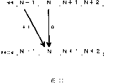
Spray pattern is existed in the buffer storage, so that it is associated together with the pixel region that will draw pixel, and sends it to corresponding nozzle (jet exit).At this moment, bit 0 order from the buffering memory reads the jet data item.Injection based on spray pattern control drop.This control procedure is shown in Figure 1B and Fig. 1 C.
Liquid sprays shower nozzle, and to be included in publication No. be Japan's disclosed inkjet printer head in the patent application of substantive examination not of 2003-226017 number.In this shower nozzle, a plurality of nozzle alignings.These nozzles are used for drawing simultaneously pixel, and the quantity of pixel is identical with the quantity of nozzle.This shower nozzle is called as " linear shower nozzle ".In this case, above-mentioned spray pattern is stored in the buffer storage, and the quantity of buffer storage is identical with the quantity of the pixel that will draw.
Summary of the invention
Consider above-mentioned situation, an object of the present invention is to address the above problem.
According to an aspect of the present invention, a kind of ejection control device is provided, it comprises: spray pattern memory cell and read address displacement (shifting) unit, wherein, the spray pattern corresponding to the gradation data item be written into described spray pattern memory cell so that its with situation that pixel region is associated under, when control from corresponding to the deflection of the drop of the jet exit of pixel region ejection so that drop on the same group drawing when not being sent to pixel region in drafting cycle of pixel, the described yawing moment that reads the address shift unit in response to each jet exit, each that will offer described spray pattern memory cell at drop injection cycle internal shift reads the address, and wherein each data item is represented gray scale by the quantity of using the drop that will be sent to each pixel region.
Preferably, the jet exit that is arranged in parallel, and when the drop direction from the ejection of all jet exits becomes (switch to) same direction simultaneously reads the address shift unit and is shifted simultaneously to single direction and reads the address.
The jet exit that can be arranged in parallel when changing (switch) from the direction of jet exit liquid droplets respectively, reads the address shift unit and can be with the jet exit unit and be shifted respectively and read the address.
When the spray pattern memory cell is made of a plurality of memory blocks, each memory block is corresponding to one group of jet exit, can at least one spray pattern of extension storage in the adjacent part of a memory block, wherein said memory block adjacent part with contiguous memory block on yawing moment is adjacent, and this spray pattern is identical with spray pattern in the adjacent part that is stored in contiguous memory block.
According to another aspect of the present invention, provide a kind of liquid droplet ejection apparatus, it comprises: ejection head unit has a plurality of jet exits that are arranged in parallel; The spray deflection unit, control makes not that from the deflection of the drop of the jet exit injection of ejection head unit drop is sent in a plurality of pixel regions on the same group in the drafting cycle of drawing pixel; The spray pattern memory cell, and read the address shift unit, when writing the spray pattern memory cell corresponding to the spray pattern of gradation data item so that it is when being associated with pixel region, wherein each data item uses the quantity of the drop that will be sent to each pixel region to represent gray scale, read the yawing moment of address shift unit in response to each jet exit, each that will offer the spray pattern memory cell at drop injection cycle internal shift reads the address.
According to another aspect of the present invention, a kind of ejection control method is provided, its comprise the following steps: will write the spray pattern memory cell corresponding to the spray pattern of gradation data item so that its with situation that pixel region is associated under, wherein each data item uses the quantity of the drop that will be sent to each pixel region to represent gray scale, when control from the deflection of the drop that sprays corresponding to the jet exit of pixel region in case will be not on the same group drop drawing when being sent to pixel region in drafting cycle of pixel, yawing moment in response to each jet exit, each that will offer the spray pattern memory cell at drop injection cycle internal shift reads the address, and the address of reading after will being shifted offers the spray pattern memory cell, and reads corresponding spray pattern.
According to another aspect of the present invention, provide a kind of computer readable recording medium storing program for performing that has program recorded thereon on it.This program makes computer executed step: will write the spray pattern memory cell corresponding to the spray pattern of gradation data item so that its with situation that pixel region is associated under, wherein each data item uses the quantity of the drop that will be sent to each pixel region to represent gray scale, when control from the deflection of the drop that sprays corresponding to the jet exit of pixel region in case will be not on the same group drop drawing when being sent to pixel region in drafting cycle of pixel, yawing moment in response to each jet exit, each that will offer the spray pattern memory cell at drop injection cycle internal shift reads the address, and the address of reading after will being shifted offers the spray pattern memory cell, and reads corresponding spray pattern.
According to another aspect of the present invention, a kind of program that makes computer carry out following function is provided: will write the spray pattern memory cell corresponding to the spray pattern of gradation data item so that its with situation that pixel region is associated under, wherein each data item uses the quantity of the drop that will be sent to each pixel region to represent gray scale, when control from the deflection of the drop that sprays corresponding to the jet exit of pixel region in case will be not on the same group drop drawing when being sent to pixel region in drafting cycle of pixel, yawing moment in response to each jet exit, each that will offer the spray pattern memory cell at drop injection cycle internal shift reads the address, and the address of reading after will being shifted offers the spray pattern memory cell, and reads corresponding spray pattern.
Description of drawings
Figure 1A, 1B and 1C are the schematic diagrames that concerns between the spray pattern of respective pixel gray scale and the pattern that plotted by the drop from the nozzle of corresponding spray pattern;
Fig. 2 is at the schematic diagram that carries out the relation of the position between the nozzle and pixel region under the zero deflection injection situation;
Fig. 3 sprays the schematic diagram of the position relation between the nozzle and pixel region under (both direction) situation carrying out deflection;
Fig. 4 is based on not considering that the spray pattern that is write that deflection is sprayed carries out under the situation that deflection sprays from the schematic diagram of the track of the drop of nozzle ejection;
Fig. 5 is the schematic diagram that rearranges of considering the spray pattern of deflection injection;
Fig. 6 shows the block diagram according to functional block of the present invention;
Fig. 7 is the schematic diagram according to notion structure of the present invention (conceptual configure);
Fig. 8 shows the block diagram of the example of signal processing unit;
Fig. 9 is the schematic diagram of the write state of spray pattern;
Figure 10 shows the block diagram of the example that reads the address shift unit;
Figure 11 is the yawing moment supposed in the shift unit of address reading as shown in figure 10 and the schematic diagram of amount of deflection;
Figure 12 supposes spray pattern that deflection is as shown in figure 11 sprayed and the relation between the spray pattern that is used to write;
Figure 13 shows the schematic diagram of other example of yawing moment and amount of deflection;
Figure 14 supposes each spray pattern that deflection is as shown in figure 13 sprayed and the relation between the spray pattern that is used to write;
Figure 15 shows the block diagram of another example that reads the address shift unit;
Figure 16 A, 16B, 16C and 16D are the schematic diagrames that reads the address shifted relationship and arrange by the point that drafting is obtained, wherein Figure 16 A shows memory construction, Figure 16 B shows yawing moment, and Figure 16 C shows and reads the address, and Figure 16 D shows the arrangement of print point;
Figure 17 shows at the block diagram that does not use the circuit structure under the situation that reads the address shift unit;
Figure 18 shows the block diagram of tiling shower nozzle (tiling head);
Figure 19 is the schematic diagram that occurs in the possible problem in the tiling shower nozzle; And
Figure 20 is when the schematic diagram of the example that reads the buffer storage of using when the address shift unit is used to tile shower nozzle.
The specific embodiment
In publication No. is Japan's above-mentioned technology in the substantive examination patent application not of 2003-226017 number, is being no problem when the drop of nozzle ejection only is sent to a pixel region as shown in Figure 2.
Yet above-mentioned technology can not directly apply to horizontal (LD, LateralDirection) spraying technique that this assignee proposes.
In the LD spraying technique, the spray deflection of the drop that electric control is sprayed.Fig. 3 shows the shower nozzle that is controlled in liquid droplets on three directions by use drop is sent to pixel region in the mode of stack.As shown in Figure 3, the gray scale of pixel is by the quantitaes of drop, and these drops spray from a plurality of nozzles (the present embodiment being two) respectively.In example shown in Figure 3, be useful on two horizontal-jet directions that drop sprays.
The spray pattern that is stored in the buffer storage is associated with each pixel region.In other words, do not consider the deflection of spraying.Therefore, by directly reading the spray pattern of a nozzle, horizontal transmission must be sent to the drop of pixel region at first as shown in Figure 4.This means that drop has been sent to undesirable position.
For avoiding as shown in Figure 5, must rearranging the jet data item that is used for spray deflection in advance owing to drop is transferred into the image scrambling that causes undesirable position.For example, as shown in Figure 5, must rearrange the jet data item, make the drop that is sprayed to be sent to identical pixel region.In Fig. 5, in the deflection cycle that will spray deflection left, jet data item right shift one row.Dash area among Fig. 5 has formed spray pattern, and wherein the delivering position of liquid droplets is corresponding to same pixel region.
Yet the rearranging of this jet data item of considering yawing moment in advance increased the quantity of arithmetical operation that gradation data is converted to the processor of spray pattern.Consider the total live width that connects processor and buffering memory, need be at bus bandwidth double that does not have under the spray deflection situation, just eight bits.On no matter still being the arithmetical operation load from hardware, rearranging of jet data item is not preferred solution.
The present invention has used technology, wherein, in response to the yawing moment of each jet exit, will offer the address of reading of spray pattern memory cell (for example, buffer storage) at drop injection cycle internal shift.Especially, as shown in Figure 6, what offer spray pattern memory cell 1 reads the address by reading 2 displacements of address shift unit.
Read address shift unit 2 by use, even controlled the deflection of the drop that sprays from the jet exit 3 in respective pixel zone, so that not on the same group drop be transferred into a plurality of pixel regions drawing in the drafting cycle of pixel, identical with the situation that does not have deflection control, spray pattern can be write in the spray pattern memory cell 1.
In other words, only need the spray pattern of corresponding grey scale data item is write in the spray pattern memory cell 1, wherein each data item is represented gray scale with the quantity of the drop that will be sent to each pixel region.Do not need spray pattern is write in the spray pattern memory cell 1 so that be associated with nozzle 3.
When the direction from the drop of all jet exits 3 ejections becomes when unidirectional simultaneously, preferably read address shift unit 2 and be shifted simultaneously to single direction and read the address.Like this, one is read the address shift unit and just can make all jet exits 3 that drop is ejected into correct position.
When the direction that changes respectively from the drop of jet exit 3 ejection, preferably reading address shift unit 2 is that unit is shifted respectively and reads the address with jet exit 3.Like this, just only being required to be one group of jet exit with equal deflection direction provides to read an address shift unit.
In addition, when spray pattern memory cell 1 is made of a plurality of memory blocks, wherein each memory block is corresponding to every group of jet exit, best, on yawing moment in the adjacent part of a memory block of the adjacent part of contiguous memory block, at least extension storage be stored in contiguous memory block part in the identical spray pattern of spray pattern.
An example has been shown among Fig. 7.Fig. 7 shows the situation that defines two conditions, is exactly, and defines and do not have deflection the situation of deflection to the right (wherein drop is from the ejection of jet exit 3 straight lines) and Fig. 7.
At this moment, suppose that the spray pattern that will be sent to n jet exit 3 is written among the 1A of memory block, preferably, by in the n+1 row, providing a zone (dash area on the left side among Fig. 7), write spray pattern in this zone, identical in first row of the contiguous memory block 1B in this spray pattern and the right (dash area on the right among Fig. 7).
In the above-mentioned situation, in yawing moment injection cycle to the right, only, just can carry out the drop injection that is suitable for spray deflection by reading the jet data in the n+1 row that are stored among the 1A of memory block and transmitting the jet data that reads in the nozzle of n row.
In the present invention, even using amount of droplets to represent that the technology of gray scale combines with the technology of deflection injection, spray pattern also is written in the spray pattern memory cell 1, and spray pattern does not use identical in the situation of deflection spraying technique with those.This can reduce load and can prevent that hardware from becoming complicated.In addition, even increasing or reducing under the situation of amount of deflection, also only need displacement to read the address.
To be example narration embodiments of the invention below with the ink-jet printer.
Suppose that each feature of not representing especially or narrating all is selected from the prior art of correlative technology field in this explanation.
In the following narration, the preferred embodiments of the present invention realize by hardware.Yet these embodiment also realize by the processing with the software of hardware equivalence.
When the present invention realized with the form of computer program, program was existed in the computer readable storage medium.
The type of this storage medium comprises, for example, magnetic storage media, as disk (floppy disk or hard disk) or tape, optical storage medium is as CD, light belt or machine readable bar code, semiconductor storage as random-access memory (ram) or read-only storage (ROM), and else is used to store the physical unit or the media of computer program.
When the present invention realizes by hardware, can realize the present invention by integrated circuit, other known equipment of for example special IC (ASIC), or affiliated technical field.
The present invention is based on the technology of the deflection injection of carrying out drop.An example of this technology has carried out describing fully in this assignee's previous application.For example, publication No. be 2002-320861 number, 2002-320862 number and 2003-037343 number etc. Japan not the substantive examination patent application this technology has all been described.Omit the repeated description of deflection spraying technique below and only narrated part related to the present invention.
1. first embodiment
1-1. circuit structure and processing operation
Fig. 8 shows part related to the present invention in the signal processing unit.Signal processing unit shown in Fig. 8 is made up of three parts, that is, and and digital signal processor (DSP) 11, printhead controller 12 and head chip 13.
This gradation data is the DMA (direct memory access (DMA)) that is sent to printhead controller 12.Especially, the gradation data of each pixel (point) is sent in proper order the scope of address 1 to the address n of corresponding shower nozzle width with the form of representing 0 to 7 four Bit datas.The four bit gradation data that pulse density modulated (PNM) unit 12A will import change eight bit spray patterns into.The corresponding injection cycle of bit difference of forming spray pattern.In first embodiment, draw the drafting cycle of pixel and form by eight injection cycles 1 to 8.
Spray pattern is that unit is written among the buffer storage 12B with eight bits.Buffer storage 12B has the double buffering structure.Especially, buffer storage 12B comprises RAM 1 and RAM 2, its each all have the storage size of delegation.RAM 1 and 2 relation are that when spray pattern write one of them, the jet data of corresponding each injection cycle read from another one.
Write counter 12C generation and provide and write the address to buffer storage 12B.This writes counter 12C generates delegation from the initial address order column address.
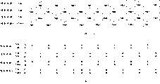
Fig. 9 shows the state that the spray pattern of delegation is write a RAM.For RAM, use RAM with 8 row n row storage sizes.The bit value " 0 " to " 7 " of expression row address is corresponding to above-mentioned injection cycle 1 to 8.
The vertical sign " PNM1 " to " PNM8 " in the right is represented the spray pattern in the injection cycle respectively.For example, indicate " PNM1 " representative one group of jet data item that spray at (at row address bits 0 place) in injection cycle 1 from n nozzle.
Reading counter 12D generates in proper order and provides and read the address to buffer storage 12B.
In first embodiment, each injection cycle is divided into 64 and cuts apart the cycle (divided period), and cuts apart liquid droplets by the time.At this moment, in this injection cycle, only drive five nozzles in the cycle cutting apart.This operates in to cut apart in the cycle and repeats, and 64 cut apart end cycle after injection cycle finish.
Therefore, for cutting apart the nozzle that drives in the cycle, read counter 12D generation and read the address, thereby can read the jet data item of use.For example, in the injection cycle 1, bit value " 0 " generates as row address, and is cutting apart in the cycle, generates 320 values as the column address that is unit with 5 values.Similarly, in injection cycle 2, bit value " 1 " generates as row address, and is cutting apart in the cycle, and 320 values generate the column address that conduct is a unit with 5 values.In turn, repeat this operation, up to injection cycle 8.
Read address shift unit 12E in response to spray deflection, displacement is read address (column address) by what low resistance 12D generated.Figure 10 shows an example that reads address shift unit 12E.This example shown in Figure 10 is at the situation that two class spray deflections are arranged.Specifically be that a class is a zero deflection.Another kind of is spray deflection to the right neighborhood pixels (having a bigger number of addresses).Yawing moment is that all nozzles of every row are common.Suppose, change yawing moment at each deflection cycle.
This situation, as shown in figure 10, for column address provides adder 12E1.Adder 12E1 receives yawing moment information (with " deflection information " expression) and column address.Yawing moment information is represented zero deflection with " 0 ", and uses the deflection of "+1 " expression to the right neighborhood pixels.In other words, as shown in Figure 11, (ink) drop that sprays from two nozzles has formed pixel.Provide yawing moment information from the memory cell (not shown).
In above-mentioned structure, read address shift unit 12E and generate column address, the jet data item of contiguous address on the right of under execution deflection situation, reading in, and provide column address to buffer storage 12B.Row address does not change.In addition, do not having under the deflection situation, reading address shift unit 12E and directly export by the address of reading of reading counter 12D generation.
The example of the processing of reading address shift unit 12E is described below with reference to Figure 12.
Among Figure 12, each yawing moment is represented by arrow.The yawing moment information that is added into each column address is represented by " 0 " or "+1 ".Under the situation in Figure 12, injection cycle 1 does not have deflection.
In each odd number injection cycle, promptly at spray pattern PNM1, PNM3, PNM5, or among the PNM7, read the address of reading that address shift unit 12E directly exports input.
On the contrary, in each even number injection cycle, promptly at spray pattern PNM2, PNM4, PNM6, or among the PNM8, read address shift unit 12E and add " 1 " and export this address to column address.Then, with input form output row address.
This has caused buffer storage 12B that spray pattern is sent to the nozzle of respective column address 0, and the position is read in displacement shown in shade among Figure 12 in the described spray pattern.
At this moment, in the odd number injection cycle, based on the drop of the jet data item that reads, " 0 ", and " 0 ", " 1 " and " 1 " is ejected into the pixel region relative with nozzle from the nozzle of respective column address 0.In the even number injection cycle, based on the drop of the jet data item that reads, " 0 ", " 1 ", " 1 " and " 0 ", be ejected into the nozzle of respective column address 0 the right adjacent pixels on.
As a result, the actual drop that is sent to pixel region with those corresponding to being stored in the identical of data item among the buffer storage 12B.In other words, all drops have been ejected into delivering position accurately.
The situation that address shift unit 12E can be applicable to three kinds of spray deflections that reads with above-mentioned structure promptly as shown in Figure 13, is sent to the situation of a pixel region in the mode of stack from the drop of three nozzle ejections.
In this case, about yawing moment information, zero deflection can be represented with "+1 " to the right neighborhood pixels deflection, and can use " 1 " expression to left side neighborhood pixels deflection with " 0 " expression.At this moment, the pattern formed by the dash area among Figure 14 of the spray pattern that from buffering memory 12B, reads.
In other words, in each injection cycle 2,5 and 8, promptly at each spray pattern PNM2, among PNM5 and the PNM8, buffer storage 12B is in constant mode, and output is being input to the jet data that reads the address that reads address shift unit 12E.
In each injection cycle 3 and 6, promptly in each spray pattern PNM3 and PNM6, buffer storage 12B exports and is input to the jet data that reads adjacent address, the right, address that reads address shift unit 12E.
In each injection cycle 1,4 and 7, promptly at each spray pattern PNM1, among PNM4 and the PNM7, buffer storage 12B exports and is input to the jet data that reads adjacent address, the left side, address that reads address shift unit 12E.
Next, description is read another example of address shift unit 12E.
Read the situation that address shift unit 12E is applicable to that all jet exits of being arranged in parallel change to equidirectional simultaneously shown in Figure 10.The address shift unit 12E that reads shown in Figure 15 is applicable to situation about changing respectively from the direction of the liquid droplets of the jet exit that is arranged in parallel.To describe in detail below and read address shift unit 12E shown in Figure 15.
Reading among the shift unit 12E of address shown in Figure 15, supposing has two kinds of spray deflections.For deflection, two kinds of deflections are arranged, i.e. zero deflection and to the deflection of the right neighbor (having bigger number of addresses).In each injection cycle, change yawing moment.The condition of having narrated reads the identical of address shift unit 12E with shown in Figure 10.
Difference is: odd column address and the corresponding different yawing moment in even column address.In other words, difference is: two yawing moments are arranged in an injection cycle.Therefore, the address shift unit 12E that reads shown in Figure 15 has two adders, promptly is used for the adder 12E1 and the adder 12E2 that is used for row address of column address.In each adder, yawing moment information is added to corresponding address.
In this structure, under the situation of deflection, read address shift unit 12E and in followed by the injection cycle after the injection cycle of contiguous address, the right (the right neighborhood pixels), generate the address that is used to read jet data, and the address that generates is offered buffer storage 12B.On the contrary, under the situation of zero deflection, read address shift unit 12E in constant mode, output is by the address of reading of reading counter 12D generation.
Below with reference to the example of Figure 16 A to 16D description by the processing of reading address shift unit 12E execution.
In Figure 16 A to 16D, yawing moment is represented by arrow.The yawing moment information that is added to each row address and each column address is represented with " 0 " and "+1 ".In order to clearly show leading (advance) in the injection cycle of relevant row address, this leading usefulness " PNM+1 " expression.In the situation shown in Figure 16 A to 16D, the corresponding no spray deflection in the odd column address in the injection cycle 1, and the even column address in the injection cycle 1 is to there being spray deflection.
Special this processing of description.Suppose that even column address in the injection cycle 1 is transfused to and read address shift unit 12E.At this moment, the drop that is injected in the pixel of column address does not have deflection.Therefore, " 0 " is transfused to each adder 12E1 and 12E2, and INADD is output to buffer storage 12B in constant mode.
In addition, supposing that even address in the injection cycle 1 is imported into reads address shift unit 12E.At this moment, for these pixels, liquid droplets deflection is to the right neighborhood pixels.
Therefore, " 1 " is transfused to each adder 12E1 and 12E2.As a result, column address has become the contiguous odd address in the right, and row address has moved on to next injection cycle 2.
Therefore, for the nozzle of corresponding even column address, in injection cycle 1, the jet data in the next injection cycle 2 is read.Therefore, shown in Figure 16 D, column address 2 places (odd column address) sends two drops in injection cycle 1, a nozzle ejection from correspondence, and another sprays from left side adjacent nozzles.In next injection cycle 2,, there is not drop to be transmitted in identical column address 2 places (odd column address).
This is because sprayed in front the injection cycle at these row drops that must spray, and because of, in injection cycle 2, drop has been sent to the pixel region that is close to.
Therefore, by using this ejection control method, two drops have been sent to very near position.Watching under the situation of established image the Different Effects picture structure that delivering position distributes.Identical with above-mentioned example, this ejection control method also is applicable to the situation with three kinds of spray deflections.
1-2. the advantage of first embodiment
As described in first embodiment, read the technology of address by adopting in response to the spray deflection displacement, can use invariably with deflection spraying technique situation in using DSP 11 under similar circuit structure and before buffer storage 12B the circuit in the stage.Therefore, do not need to design new digital signal processing circuit.In addition, can also avoid the increase of possible complicated and circuit scale.
The technology that adopts displacement to read the address can easily be tackled the situation that changes yawing moment and amount of deflection, and reply changes the situation of deflection order.This technology can easily be tackled with stacked system and spray the increase of quantity of nozzle of the drop that will be transmitted or the situation of minimizing.Therefore, this technology is of great use for effectively utilizing the available circuit element and improving resolution ratio.
For reference, illustrated among Figure 17 do not have to use as first embodiment in displacement read circuit structure under the situation of address.When carrying out the rearranging of spray pattern, use circuit structure shown in Figure 17 handling.Use the foregoing circuit structure not only to need the DSP 11A of design specialized, make that also the processing time among the DSP 11A is longer.The width of the data/address bus between DSP 11A and the printhead controller 12 is increased to eight bits.
1. second embodiment
1-1. circuit structure and processing operation
Next, with the second embodiment of the invention of describing under the situation that will above-mentioned first embodiment be applied to the shower nozzle that tiles.
The tiling shower nozzle is that as shown in figure 18, its shower nozzle partly is divided into a plurality of head chips.RAM 1 and RAM 2 (Fig. 8) among RAM 1 shown in Figure 18 and the corresponding buffer storage 12B of RAM 2 difference.
The jet data item is from storage chip 1 to the N parallel head chip that is sent to of corresponding head chip.During the read method in using first embodiment, described, as shown in figure 19, be arranged in the borderline jet data of head chip and be stored in two storage chips.Therefore, realize above-mentioned reading, need the circuit of the data/address bus that changes two storage chips.
In a second embodiment, the technology that does not need the data/address bus varying circuit is used in suggestion.Therefore, in a second embodiment, the spray pattern of corresponding head chip boundary member is recorded in the contiguous storage chip with copy mode (duplicativemanner).
Particularly, as shown in figure 20, in the boundary member of each memory chip, provide redundant area.Address width in the redundant area on the line direction is identical with the original storage chip.Address width in the redundant area on the column direction is consistent with amount of deflection.
Amount of deflection is determined by the amount of spraying the drop that is shifted by deflection contiguously.For example, amount of deflection can be corresponding to the displacement of two pixels of drop position, the perhaps displacement of three of the drop position pixels.
When amount of deflection during corresponding to the displacement of a pixel of drop position, as shown in figure 20, the address width in the redundant area on the column direction is equivalent to a pixel.As mentioned above, under the situation of spraying unilateral deflection, only provide the redundant area of each storage chip in a side.As shown in figure 14, when spraying, promptly when positive direction and negative direction, provide redundant area at the opposite side of each storage chip to both direction deflection.
Consider redundant area, the counter 12C that writes that is used for second embodiment needs to revise.
Consider that the correction of redundant area can so carry out, write counter 12C operation, so that when data were transferred into two borders between the contiguous storage chip, data can be written into borderline two addresses and locate.
For example, when the initial column address place of printhead controller 12 between two contiguous storage chips write spray pattern, it so moved so that the last column address of a storage chip was designated as in the phase I and writes the zone.
For this purpose, for example adopt such technology, wherein write the last column address of counter 12C at a storage chip of phase I generation, generate the initial column address of next stage simultaneously.In addition, for example adopt another technology, wherein, in writing counter 12C, the last column address of a storage chip is latched (latched) in the phase I, and when the initial column address in next stage of this storage chip is generated, offers buffer storage 12B.
Alternatively, also can adopt the method for the address wire that changes buffer storage 12B.For example, address wire is wired, so that when generating particular address, also will be appointed as in the particular address in the phase I storage chip and write the zone.
In addition, also can adopt such method, wherein when DSP 11 detected spray pattern and need duplicate, spray pattern was exported with copy mode.In other words, the data that write redundant area are exported with copy mode, and in the redundant area of writing direct.
As mentioned above, there is different possible methods to realize above-mentioned reading.Borderline spray pattern only need write the address that to be generated so that can write in the specific redundancy zone.
2-2. the advantage of second embodiment
As described in second embodiment, by redundant area being provided for each storage chip that forms buffer storage 12B, and duplicate record belongs to the spray pattern of another storage chip in redundant area, even the spray deflection from the tiling ejection head unit is controlled, drop also can only read the address by displacement and be injected into accurate position.
In addition, can realize reading reading of address by the circuit structure of simplifying, and not need the special circuit structure.
The present invention is applicable to the printer head unit, and it sprays ink droplet from shower nozzle.The present invention also is applicable to the signal processing circuit in the ejection head unit.In addition, the present invention is applicable to printer and other electrical equipments that comprise ejection head unit.By printer thereon the object of print image be not limited only to paper, can also be plastic material, metal material, or the object of other types.In addition, the present invention is applicable to the checkout facility that sprays sample with the drop form.
Claims (8)
Applications Claiming Priority (3)
| Application Number | Priority Date | Filing Date | Title |
|---|---|---|---|
| JP314316/03 | 2003-09-05 | ||
| JP314316/2003 | 2003-09-05 | ||
| JP2003314316A JP4148074B2 (en) | 2003-09-05 | 2003-09-05 | Discharge control device, liquid discharge device, liquid discharge method, recording medium, and program |
Publications (2)
| Publication Number | Publication Date |
|---|---|
| CN1600545A true CN1600545A (en) | 2005-03-30 |
| CN100341698C CN100341698C (en) | 2007-10-10 |
Family
ID=34131909
Family Applications (1)
| Application Number | Title | Priority Date | Filing Date |
|---|---|---|---|
| CNB2004100905221A Expired - Fee Related CN100341698C (en) | 2003-09-05 | 2004-09-06 | Ejection control device, liquid ejecting device, liquid ejecting method, and recording medium and program used therewith |
Country Status (7)
| Country | Link |
|---|---|
| US (2) | US7185961B2 (en) |
| EP (1) | EP1512538B1 (en) |
| JP (1) | JP4148074B2 (en) |
| KR (1) | KR101054977B1 (en) |
| CN (1) | CN100341698C (en) |
| DE (1) | DE602004032411D1 (en) |
| SG (1) | SG109606A1 (en) |
Cited By (2)
| Publication number | Priority date | Publication date | Assignee | Title |
|---|---|---|---|---|
| CN103448390A (en) * | 2012-06-05 | 2013-12-18 | 北大方正集团有限公司 | Digital printing control method and equipment |
| CN103718020A (en) * | 2012-03-30 | 2014-04-09 | 索尼公司 | Microparticle fractionation apparatus, and method for optimizing fluid stream in said apparatus |
Family Cites Families (17)
| Publication number | Priority date | Publication date | Assignee | Title |
|---|---|---|---|---|
| JP3409797B2 (en) | 1992-06-30 | 2003-05-26 | 株式会社日立製作所 | Print distortion correction device for inkjet printer |
| JPH0948129A (en) | 1995-08-08 | 1997-02-18 | Toray Ind Inc | Inkjet recording method |
| US6074046A (en) * | 1998-03-06 | 2000-06-13 | Eastman Kodak Company | Printer apparatus capable of varying direction of an ink droplet to be ejected therefrom and method therefor |
| JP4208399B2 (en) * | 1999-10-12 | 2009-01-14 | キヤノン株式会社 | Inkjet recording apparatus and inkjet recording method |
| JP2001105584A (en) * | 1999-10-14 | 2001-04-17 | Canon Inc | Ink jet recording device |
| DE60142867D1 (en) * | 2000-01-20 | 2010-10-07 | Sony Corp | METHOD FOR DRIVING A RECORDING HEAD, RECORDING HEAD AND INK JET PRESSURE DEVICE |
| US6457798B1 (en) * | 2000-11-27 | 2002-10-01 | Xerox Corporation | Six gray level roofshooter fluid ejector |
| JP4617571B2 (en) * | 2000-12-19 | 2011-01-26 | リコープリンティングシステムズ株式会社 | Multi-nozzle inkjet recording device |
| JP2002192727A (en) * | 2000-12-27 | 2002-07-10 | Canon Inc | An ink jet recording head, an ink jet recording apparatus and inkjet recording method |
| US6478414B2 (en) * | 2000-12-28 | 2002-11-12 | Eastman Kodak Company | Drop-masking continuous inkjet printing method and apparatus |
| JP2002320862A (en) | 2001-04-26 | 2002-11-05 | Asahi Kasei Corp | Photocatalytic thin film with metal supported on titanium oxide thin film |
| JP2002320861A (en) | 2001-04-27 | 2002-11-05 | Daicel Chem Ind Ltd | Metal catalyst separation method |
| JP2003037343A (en) | 2001-07-24 | 2003-02-07 | Hitachi Kokusai Electric Inc | Mounting substrate for surface acoustic wave devices |
| JP2003051003A (en) * | 2001-08-08 | 2003-02-21 | Canon Inc | Image processing apparatus, image recording apparatus, and control method thereof |
| JP2003170577A (en) * | 2001-12-05 | 2003-06-17 | Sony Corp | Image forming apparatus and image forming method |
| JP2003226017A (en) | 2002-02-04 | 2003-08-12 | Sony Corp | Inkjet printer head |
| JP2004001364A (en) * | 2002-04-16 | 2004-01-08 | Sony Corp | Liquid ejection device and liquid ejection method |
-
2003
- 2003-09-05 JP JP2003314316A patent/JP4148074B2/en not_active Expired - Fee Related
-
2004
- 2004-09-03 EP EP04020990A patent/EP1512538B1/en not_active Expired - Lifetime
- 2004-09-03 US US10/934,214 patent/US7185961B2/en not_active Expired - Fee Related
- 2004-09-03 DE DE602004032411T patent/DE602004032411D1/en not_active Expired - Lifetime
- 2004-09-03 SG SG200405017A patent/SG109606A1/en unknown
- 2004-09-06 KR KR1020040070885A patent/KR101054977B1/en not_active Expired - Fee Related
- 2004-09-06 CN CNB2004100905221A patent/CN100341698C/en not_active Expired - Fee Related
-
2007
- 2007-03-05 US US11/714,889 patent/US7621610B2/en not_active Expired - Fee Related
Cited By (4)
| Publication number | Priority date | Publication date | Assignee | Title |
|---|---|---|---|---|
| CN103718020A (en) * | 2012-03-30 | 2014-04-09 | 索尼公司 | Microparticle fractionation apparatus, and method for optimizing fluid stream in said apparatus |
| CN103718020B (en) * | 2012-03-30 | 2016-06-29 | 索尼公司 | Particle sorting device and the method optimizing fluid stream in the apparatus |
| CN103448390A (en) * | 2012-06-05 | 2013-12-18 | 北大方正集团有限公司 | Digital printing control method and equipment |
| CN103448390B (en) * | 2012-06-05 | 2016-06-29 | 北大方正集团有限公司 | A kind of digital printing control method and equipment |
Also Published As
| Publication number | Publication date |
|---|---|
| CN100341698C (en) | 2007-10-10 |
| EP1512538A3 (en) | 2007-02-28 |
| KR20050025099A (en) | 2005-03-11 |
| US7621610B2 (en) | 2009-11-24 |
| SG109606A1 (en) | 2005-03-30 |
| KR101054977B1 (en) | 2011-08-05 |
| DE602004032411D1 (en) | 2011-06-09 |
| US7185961B2 (en) | 2007-03-06 |
| JP4148074B2 (en) | 2008-09-10 |
| US20050078135A1 (en) | 2005-04-14 |
| US20070159506A1 (en) | 2007-07-12 |
| EP1512538B1 (en) | 2011-04-27 |
| EP1512538A2 (en) | 2005-03-09 |
| JP2005081621A (en) | 2005-03-31 |
Similar Documents
| Publication | Publication Date | Title |
|---|---|---|
| CN1310758C (en) | Ink-jet printing method, printing system, ink-jet printing apparatus, print data generating method, program and printer driver | |
| CN1530229A (en) | Recorder and recording method thereof | |
| CN1320521A (en) | Print head, print head driving method and data output device | |
| CN1738718A (en) | Method of informing a user of end of life of a consumable for an ink jet printer | |
| CN101045381A (en) | Printing head, printing device, serial data generating device and computer programming | |
| CN1090093C (en) | Ink jet printer and drive method thereof | |
| CN1168320A (en) | Multi-unit printer and adjustment method for such a printer | |
| CN1407928A (en) | Ink jet recording head driving method and circuit therefor | |
| CN1769053A (en) | Printing method and apparatus for an ink-jet printer having a wide printhead | |
| CN1907713A (en) | Printing apparatus and control method therefor | |
| CN1452123A (en) | Recording device and recording device controlling method | |
| JP4687745B2 (en) | Image processing apparatus, image recording system, and program | |
| CN1064765C (en) | Printer having scroll print buffer and printing method | |
| CN1452368A (en) | Controlling device and method | |
| CN1181976C (en) | printer | |
| JP2006021532A (en) | Inkjet recording method | |
| CN100335282C (en) | Ink-jet recording device and control method for such ink-jet recording device | |
| CN1600545A (en) | Ejection control device, liquid ejecting device, liquid ejecting method, and recording medium and program used therewith | |
| JP4370080B2 (en) | Image recording device | |
| JP2009006611A (en) | Ink jet recording apparatus and recording method thereof | |
| US8419151B2 (en) | Inkjet printer | |
| US6786564B2 (en) | Inkjet printer, drive method and drive device for same | |
| CN1929999A (en) | Ink-jet recording method | |
| CN1683159A (en) | Ink jet recording apparatus and method of controlling the same for complementary recording | |
| JP2011076156A (en) | Apparatus and method for processing image |
Legal Events
| Date | Code | Title | Description |
|---|---|---|---|
| C06 | Publication | ||
| PB01 | Publication | ||
| C10 | Entry into substantive examination | ||
| SE01 | Entry into force of request for substantive examination | ||
| C14 | Grant of patent or utility model | ||
| GR01 | Patent grant | ||
| CF01 | Termination of patent right due to non-payment of annual fee |
Granted publication date: 20071010 Termination date: 20150906 |
|
| EXPY | Termination of patent right or utility model |