光学头装置及光盘装置以及光学装置及复合光学元件Optical head device, optical disk device, optical device, and composite optical element
技术领域technical field
本发明涉及对于磁光盘、相变化型的光盘等进行光学信息的记录再现的光盘,进行信息的记录及/或再现的光学头装置及具备光学头装置的光盘装置,以及这些装置中采用的光学装置及一体形成光学装置的复合光学元件。The present invention relates to an optical disc for recording and reproducing optical information on a magneto-optical disc, a phase-change optical disc, etc., an optical head device for recording and/or reproducing information, an optical disc device equipped with an optical head device, and optical disc devices used in these devices. The device and the composite optical element integrally forming the optical device.
本申请以日本2001年11月22日申请的日本专利申请号2001-358244及2002年8月2日申请的日本专利申请号2002-226764为基础要求优先权,这些申请通过参考结合到本申请中。This application claims priority based on Japanese Patent Application No. 2001-358244 filed on November 22, 2001 and Japanese Patent Application No. 2002-226764 filed on August 2, 2002, which are incorporated by reference into this application .
背景技术Background technique
以前,为了再现各种各样的记录格式信息的光盘如CD(CompactDisk)和DVD(Digital Versatile Disk)光盘,有具备可出射与各个格式对应的波长的激光的光源和光学系统的光学头装置。In the past, in order to reproduce optical discs with various recording formats such as CD (Compact Disk) and DVD (Digital Versatile Disk) optical discs, there are optical head devices equipped with light sources and optical systems that can emit laser light with wavelengths corresponding to each format.
作为该种光学头装置,如具备如图1所示的光学系统201。图1所示的光学系统201按照光路顺序具备:向光盘204选择出射相互不同波长的激光的2波长光源211;将该2波长光源211出射的出射光分割成3束的3光束用衍射光栅212;将出射光和来自光盘204的返回光分离的光束分离器213;将出射光收缩到规定的孔径数NA的孔径光阑214;将出射光会聚到光盘204的2波长物镜215;接受来自光盘204的返回光的受光部216。Such an optical head device includes, for example, an optical system 201 as shown in FIG. 1 . The optical system 201 shown in FIG. 1 includes, in order of optical paths: a two-wavelength light source 211 that selectively emits laser light of mutually different wavelengths to the optical disc 204; and a three-beam diffraction grating 212 that divides the emitted light emitted by the two-wavelength light source 211 into three beams. ; the beam splitter 213 for separating the outgoing light and the return light from the optical disc 204; the aperture diaphragm 214 that shrinks the outgoing light to a prescribed aperture number NA; 204 of the return light to the light receiving unit 216 .
2波长光源211采用半导体激光器,从发光点211a选择出射例如大致785nm的激光和大致655nm的波长的激光。The two-wavelength light source 211 is a semiconductor laser, and selectively emits, for example, a laser beam with a wavelength of about 785 nm and a laser beam with a wavelength of about 655 nm from the light emitting point 211 a.
3光束用衍射光栅212为了通过所谓3光束法获得跟踪误差信号,将2波长光源211出射的出射光分割成0次光及±1次光组成的3光束。The 3-beam diffraction grating 212 divides the emitted light from the 2-wavelength light source 211 into 3 beams consisting of 0-order light and ±1-order light in order to obtain a tracking error signal by a so-called 3-beam method.
光束分离器213具有将2波长光源211出射的出射光向光盘204方向反射的半透明反射镜面213a,通过将2波长光源211出射的出射光向光盘204方向反射同时使来自光盘204的返回光透过并导入受光部216,使出射光和返回光的光路分离。The beam splitter 213 has a semi-transparent mirror surface 213a that reflects the outgoing light emitted by the two-wavelength light source 211 toward the direction of the optical disc 204, and transmits the return light from the optical disc 204 by reflecting the outgoing light emitted by the two-wavelength light source 211 toward the direction of the optical disc 204. Passed and introduced into the light receiving unit 216, the optical paths of outgoing light and returning light are separated.
受光部216在受光面216a上具有:接受由返回光中3光束用衍射光栅212分割的0次光的后述的主光束用光检测器221;分别接受由返回光中3光束用衍射光栅212分割的±1次光的一组未图示侧光束用光检测器。The light receiving unit 216 has, on the light receiving surface 216a, a main beam photodetector 221 to be described later that receives the 0-order light divided by the 3-beam diffraction grating 212 in the return light; A group of photodetectors for the side beams (not shown) of the divided ±1-order light.
光学系统201采用所谓象散法作为检测聚焦误差信号的检测方法。因而,如图2A、图2B、图2C所示,主光束用光检测器221中,接受返回光的受光面形成大致方形状,并采用具有由通过受光面的中央的相互正交的一组分割线4等分割的各受光区域a5、b5、c5、d5的分割图案。另外,侧光束用光检测器夹着主光束用光检测器221分别配置在对置位置上。The optical system 201 employs a so-called astigmatism method as a detection method for detecting a focus error signal. Therefore, as shown in FIG. 2A, FIG. 2B, and FIG. 2C, in the photodetector 221 for the main beam, the light-receiving surface that receives the return light is formed in a substantially square shape, and a group of mutually orthogonal beams that pass through the center of the light-receiving surface are adopted. A division pattern of each of the light receiving regions a 5 , b 5 , c 5 , and d 5 equally divided by the division line 4 . In addition, the photodetectors for side beams are respectively arranged at opposing positions with the photodetector 221 for main beams interposed therebetween.
光学系统201如图1所示,在从2波长光源211到光盘204的往路中分别配置各光学部件,使得2波长光源211的发光点211a或发光点211b作为物点,其共轭点即像点位于光盘204的记录面205上。Optical system 201, as shown in FIG. 1 , is equipped with various optical components on the way from 2-wavelength light source 211 to optical disc 204, so that luminous point 211a or luminous point 211b of 2-wavelength light source 211 serves as an object point, and its conjugate point is the image The dots are located on the recording surface 205 of the optical disc 204 .
另外,光学系统201在从光盘204到受光部216的归路中分别配置各光学部件,使光盘204的记录面205上的点作为物点,其共轭点即像点位于受光部216的主光束用光检测器221的受光面上。In addition, the optical system 201 arranges each optical component in the return path from the optical disc 204 to the light receiving unit 216, so that a point on the recording surface 205 of the optical disc 204 is used as an object point, and its conjugate point, that is, an image point, is located at the main point of the light receiving unit 216. The light beam is on the light receiving surface of the photodetector 221 .
从而,光学系统201中,2波长光源211的发光点和受光部216的主光束用光检测器221的受光面上的点也具有相互共轭的关系。Therefore, in the optical system 201 , the light-emitting point of the two-wavelength light source 211 and the point on the light-receiving surface of the main-beam photodetector 221 of the light-receiving unit 216 also have a mutual conjugate relationship.
以下说明通过上述主光束用光检测器221的各受光区域a5、b5、c5、d5获得聚焦误差信号的方法。A method of obtaining a focus error signal from each of the light receiving regions a 5 , b 5 , c 5 , and d 5 of the above-mentioned main beam photodetector 221 will be described below.
首先,若令相对于光盘204的记录面205,2波长物镜215处于最佳位置,即对光盘204的记录面205聚焦的所谓精确聚焦的状态,则主光束用光检测器221的受光面上的光束光斑的形状形成图2B所示的圆形。First, if the 2-wavelength objective lens 215 is at an optimal position with respect to the recording surface 205 of the optical disc 204, that is, in a so-called precisely focused state of focusing on the recording surface 205 of the optical disc 204, then the light receiving surface of the photodetector 221 for the main beam The shape of the beam spot forms a circle as shown in Figure 2B.
但是,2波长物镜215过于靠近光盘204的记录面205的场合,从精确聚焦的状态偏离,由于由光束分离器用衍射光栅212b分离的返回光通过复合光学元件212而发生的象散,主光束用光检测器221的受光面上的光束光斑的形状,成为如图2A所示其长轴跨越受光区域a5及受光区域c5的椭圆形状。However, when the 2-wavelength objective lens 215 is too close to the recording surface 205 of the optical disc 204, it deviates from the state of precise focus, and due to the astigmatism that occurs when the return light separated by the diffraction grating 212b for the beam splitter passes through the composite optical element 212, the main beam The shape of the beam spot on the light-receiving surface of the photodetector 221 is an ellipse whose long axis spans the light-receiving region a5 and the light-receiving region c5 as shown in FIG. 2A .
而且,2波长物镜215过于远离光盘204的记录面205的场合,从精确聚焦的状态偏离,由于由光束分离器用衍射光栅212b分离的返回光通过复合光学元件212而发生的象散,主光束用光检测器221的受光面上的光束光斑的形状成为如图2C所示其长轴跨越受光区域b5及受光区域d5的椭圆形状,是与上述图2A所示光束光斑的形状相比其长轴方向倾斜了90度的椭圆形状。Moreover, when the 2-wavelength objective lens 215 is too far away from the recording surface 205 of the optical disc 204, it deviates from the state of precise focus, and due to the astigmatism that occurs when the return light separated by the diffraction grating 212b for the beam splitter passes through the composite optical element 212, the main beam The shape of the beam spot on the light receiving surface of the photodetector 221 becomes an ellipse whose major axis crosses the light receiving region b5 and the light receiving region d5 as shown in FIG. An elliptical shape in which the major axis direction is inclined by 90 degrees.
主光束用光检测器221中,若令各受光区域a5、b5、c5、d5的返回光的输出分别为Sa5、Sb5、Sc5、Sd5,则聚焦误差信号FE由以下的式1进行计算。In the photodetector 221 for the main beam, if the output of the return light of each light receiving area a5 , b5 , c5 , and d5 is respectively Sa5 , Sb5 , Sc5 , and Sd5 , the focus error signal FE is given by The following formula 1 was used for calculation.
FE=(Sa5+Sc5)-(Sb5+Sd5)····(1)FE=(Sa 5 +Sc 5 )-(Sb 5 +Sd 5 )····(1)
即,如图2B所示,当主光束用光检测器221中,2波长物镜215为位于聚焦位置的所谓精确聚焦的状态时,由上述式1运算的聚焦误差信号FE成为0。That is, as shown in FIG. 2B , when the two-wavelength objective lens 215 is in a so-called fine-focus state at the in-focus position in the main beam photodetector 221 , the focus error signal FE calculated by Equation 1 above becomes zero.
另外,主光束用光检测器221中,2波长物镜215过于靠近光盘204的记录面205的场合,聚焦误差信号FE成为正,而2波长物镜215过于远离光盘204的记录面205的场合,聚焦误差信号FE成为负。In addition, in the main beam photodetector 221, when the 2-wavelength objective lens 215 is too close to the recording surface 205 of the optical disc 204, the focus error signal FE becomes positive, and when the 2-wavelength objective lens 215 is too far from the recording surface 205 of the optical disc 204, the focus error signal FE becomes positive. The error signal FE becomes negative.
跟踪误差信号TE可通过侧光束用光检测器分别接受由3光束用衍射光栅212a分割的±1次光并运算各侧光束用光检测器的各输出的差分来获得。The tracking error signal TE can be obtained by receiving ±1st order light divided by the 3-beam diffraction grating 212a at each of the side beam photodetectors and calculating the difference between the outputs of the respective side beam photodetectors.
具备如上所述构成的光学系统201的光学头装置,根据由受光部216的主光束用光检测器221获得的聚焦误差信号FE及由侧光束用光检测器获得的跟踪误差信号TE,驱动移动2波长物镜215,使2波长物镜215相对于光盘204的记录面205移动到聚焦位置,出射光聚焦到光盘204的记录面205上,再现光盘204信息。The optical head device equipped with the optical system 201 configured as above is driven to move according to the focus error signal FE obtained by the photodetector 221 for the main beam of the light receiving part 216 and the tracking error signal TE obtained by the photodetector for the side beam. The 2-wavelength objective lens 215 moves the 2-wavelength objective lens 215 to a focus position with respect to the recording surface 205 of the optical disc 204, and the emitted light is focused on the recording surface 205 of the optical disc 204 to reproduce information from the optical disc 204.
但是,一般地说,2波长光源211等的半导体激光器的激光的振荡波长具有依赖于周围的温度的性质。周围的温度为T时,若令温度T下的振荡波长为λT,常温下的振荡波长为λ0,从常温变化的温度为ΔT,温度系数为c,则半导体激光器的激光的振荡波长可用以下所示式2近似表示。However, in general, the oscillation wavelength of laser light of semiconductor lasers such as the two-wavelength light source 211 has a property of depending on the ambient temperature. When the ambient temperature is T, if the oscillation wavelength at temperature T is λ T , the oscillation wavelength at normal temperature is λ 0 , the temperature changing from normal temperature is ΔT, and the temperature coefficient is c, then the laser oscillation wavelength of the semiconductor laser can be used Equation 2 shown below is an approximate representation.
λT=λ0+c·ΔT····(2)λ T = λ 0 +c·ΔT····(2)
另外,激光入射衍射光栅并衍射时,令入射角为θ,衍射角为θ’,则入射角θ和衍射角θ’的关系可用以下所示式3表示。In addition, when the laser light enters the diffraction grating and diffracts, let the incident angle be θ and the diffraction angle be θ', then the relationship between the incident angle θ and the diffraction angle θ' can be expressed by the following formula 3.
n’·sinθ’-n·sinθ=m·λ/d····(3)n' sinθ'-n sinθ=m·λ/d····(3)
另外,λ是激光的波长,d是衍射光栅的光栅常数,m是衍射次数,n是入射侧媒质的折射率,n’是出射侧媒质的折射率。例如,返回光由衍射光栅衍射并光路分离时,由于对于主光束为n=1、θ=0,因而若令衍射次数为+1次,则式3可以成为以下所示式4。In addition, λ is the wavelength of the laser light, d is the grating constant of the diffraction grating, m is the diffraction order, n is the refractive index of the medium on the incident side, and n' is the refractive index of the medium on the outgoing side. For example, when the returning light is diffracted by a diffraction grating and the optical paths are separated, since n=1 and θ=0 for the main beam, if the order of diffraction is +1, then Equation 3 can be expressed as Equation 4 below.
n’·sinθ’=λ/d····(4)n' sinθ'=λ/d····(4)
通过上述式2至式4,该光学系统所在的环境温度变化时,若令温度T中的衍射角为θ’T,将式2代入式4,则可获得以下所示式5。Through the above formulas 2 to 4, when the ambient temperature of the optical system changes, if the diffraction angle at the temperature T is θ' T , and substituting formula 2 into formula 4, the following formula 5 can be obtained.
n’·sinθ’T=(λ0+c·ΔT)/d····(5)n'·sinθ' T =(λ 0 +c·ΔT)/d····(5)
而且,令常温下的衍射角为θ’0,利用衍射角θ’0从式5可获得以下所示式6。Furthermore, assuming that the diffraction angle at normal temperature is θ' 0 , the following formula 6 can be obtained from formula 5 using the diffraction angle θ' 0 .
n’·sinθ’T=n’·sinθ’0+c·ΔT/d····(6)n'·sinθ' T =n'·sinθ' 0 +c·ΔT/d····(6)
通过式6,温度T下的衍射角θ’T可用以下所示式7表示。From Equation 6, the diffraction angle θ' T at temperature T can be represented by Equation 7 shown below.
θ’T=θ’0+sin-1((c·ΔT)/(d·n’))····(7)θ' T =θ' 0 +sin -1 ((c·ΔT)/(d·n'))····(7)
通过式7,可明白返回光的温度T中的衍射角θ’T依赖于ΔT,即依赖于光学系统的环境温度变化。From Equation 7, it can be understood that the diffraction angle θ' T in the temperature T of the returned light depends on ΔT, that is, depends on the change in the ambient temperature of the optical system.
接着,光学头装置中,由于制造工序在常温进行,因而受光部的位置在返回光的衍射角作为θ’0的情况下进行调整。但是,受光部的位置调整后,环境温度若变化,则式3所示返回光的衍射角变化,例如,如图3所示,照射到受光部216的主光束用光检测器221的受光面上的光束光斑的中心从规定的位置偏移。Next, in the optical head device, since the manufacturing process is performed at room temperature, the position of the light receiving unit is adjusted with the diffraction angle of the return light being θ'0 . However, after the position of the light receiving unit is adjusted, if the ambient temperature changes, the diffraction angle of the return light shown in Equation 3 will change. For example, as shown in FIG. The center of the spot on the beam is offset from the specified position.
上述光学头装置具备的光学系统201中,通过上述受光部216获得聚焦误差信号FE时,照射到主光束用光检测器221的受光面上的光束光斑的中心从主光束用光检测器221的中央向任一方向即使稍微偏离,精确聚焦状态下的输出都不是0,因而,在结果的聚焦误差信号FE上产生了偏移量。In the optical system 201 included in the above-mentioned optical head device, when the focus error signal FE is obtained by the light receiving unit 216, the center of the beam spot irradiated on the light receiving surface of the main beam photodetector 221 is separated from the center of the main beam photodetector 221. Even if the center deviates slightly in either direction, the output in the fine focus state is not 0, and therefore, an offset is generated in the resulting focus error signal FE.
如上所述,光学头装置中存在以下问题,即不能将2波长物镜215驱动控制到正确聚焦位置,以便进行聚焦控制使得聚焦误差信号FE成为0。As described above, there is a problem in the optical head device that the drive control of the 2-wavelength objective lens 215 to the correct focus position is impossible to perform focus control so that the focus error signal FE becomes zero.
另外,上述光学头装置中,必须将受光部216正确配置到受光部216的封装位置基准,由于位置精度严,有生产性变差的问题。In addition, in the optical head device described above, the light receiving unit 216 must be accurately arranged to the package position reference of the light receiving unit 216, and there is a problem that productivity deteriorates due to strict positional accuracy.
发明的公开disclosure of invention
本发明的目的在于提供:将来自光盘的返回光导入适当的位置,可提高聚焦误差信号的可靠性的光学装置、复合光学元件、光学头装置及光盘装置。An object of the present invention is to provide an optical device, a composite optical element, an optical head device, and an optical disc device that guide return light from an optical disc to an appropriate position and improve the reliability of a focus error signal.
为了达到上述目的而提案的本发明的光学头装置,包括:光源,出射相互不同波长的出射光;物镜,会聚光源出射到光盘的出射光,同时会聚来自光盘的返回光;复合光学元件,它包括第1衍射元件和至少一个光路变动补正部件,所述第1衍射元件使光源出射的出射光透过并衍射来自光盘的返回光,所述至少一个光路变动补正部件配置于由第1衍射元件衍射的返回光入射的位置,补正因光源出射的出射光的波长变动在第1衍射元件中产生的返回光的光路变动,将返回光导入规定的位置;受光部件,用多个受光区域接受由光路变动补正部件补正了光路变动的返回光。The optical head device of the present invention proposed in order to achieve the above-mentioned purpose includes: a light source, which emits outgoing lights of different wavelengths; Comprising a first diffractive element and at least one optical path variation correction component, the first diffractive element transmits the outgoing light emitted by the light source and diffracts the return light from the optical disc, and the at least one optical path variation correction component is arranged on the first diffractive element The incident position of the diffracted return light corrects the optical path change of the return light generated in the first diffraction element due to the wavelength change of the outgoing light emitted by the light source, and guides the return light to a predetermined position; The optical path fluctuation correcting means corrects the return light of the optical path fluctuation.
该光学头装置,将光源出射的出射光通过物镜会聚到光盘,将光盘的返回光用复合光学元件内的第1衍射元件衍射而与出射光的光路分离。然后,光学头装置,通过光路变动补正部件补正由光源出射的出射光的波长变动在第1衍射元件中产生的返回光的光路变动,将返回光导入受光部件的规定的位置,受光部件通过多个受光区域接受导入规定的位置的返回光,从而获得适当的聚焦误差信号。In this optical head device, outgoing light emitted from a light source is converged onto an optical disk through an objective lens, and the returning light from the optical disk is diffracted by the first diffraction element in the composite optical element to separate from the optical path of the outgoing light. Then, the optical head device corrects the optical path variation of the returning light generated in the first diffraction element by the wavelength variation of the outgoing light emitted by the light source through the optical path variation correction part, and guides the returning light into a predetermined position of the light receiving part, and the light receiving part passes through multiple Each light-receiving area receives the return light guided to a predetermined position, thereby obtaining an appropriate focus error signal.
本发明的其他光学头装置,具备:光源,出射相互不同波长的光;物镜,会聚光源出射到光盘的出射光,同时会聚来自光盘的返回光;光束分离器,分离光源出射的出射光和光盘反射的返回光的光路;光路合成部件,补正由光源的各个波长的发光点的位置偏移引起的一个波长的出射光的光路相对于另一个波长的出射光的光路的偏移;光分割部件,配置于由光束分离器分离并由光路合成部件补正了光路的偏移的返回光入射的位置,将返回光分割成多个;受光部件,通过多个受光区域接受由光分割部件分割的多个返回光,光分割部件是由多个平面或曲面构成的棱镜。Other optical head devices of the present invention include: a light source that emits light of different wavelengths from each other; an objective lens that converges the outgoing light emitted by the light source to the optical disk and simultaneously converges the return light from the optical disk; a beam splitter that separates the outgoing light emitted by the light source and the optical disk. The optical path of the reflected return light; the optical path synthesis component, which corrects the offset of the optical path of the outgoing light of one wavelength relative to the optical path of the outgoing light of the other wavelength caused by the positional deviation of the light-emitting point of each wavelength of the light source; the optical division component , arranged at the incident position of the return light separated by the beam splitter and corrected by the optical path combining part to split the return light into multiple; return light, the light splitting component is a prism composed of multiple planes or curved surfaces.
该光学头装置,将光源出射的出射光导入光盘,将来自光盘的返回光通过光束分离器分离成与出射光不同的光路,补正由发光点的位置偏移引起的一个波长的出射光的光路相对于另一个波长的出射光的光路的偏移,从而调整使得返回光入射光分割部件的规定的位置。This optical head device guides the outgoing light emitted by the light source into the optical disc, splits the return light from the optical disc into an optical path different from the outgoing light through the beam splitter, and corrects the optical path of the outgoing light of one wavelength caused by the positional deviation of the light emitting point. With respect to the shift of the optical path of the outgoing light of another wavelength, the predetermined position where the return light enters the light splitting member is adjusted.
本发明的光盘装置,具备使光盘记录及/或再现信息的光学头和旋转驱动光盘的盘旋转驱动部件,光学头具备:光源,出射相互不同波长的出射光;物镜,会聚光源出射到光盘的出射光,同时会聚来自光盘的返回光;复合光学元件,它包括第1衍射元件和至少一个光路变动补正部件,所述第1衍射元件使光源出射的出射光透过并衍射来自光盘的返回光,所述至少一个光路变动补正部件配置于由第1衍射元件衍射的返回光入射的位置,补正因光源出射的出射光的波长变动在第1衍射元件中产生的返回光的光路变动,将返回光导入规定的位置;受光部件,用多个受光区域接受由光路变动补正部件补正了光路变动的返回光。The optical disc device of the present invention is provided with an optical head for recording and/or reproducing information on the optical disc and a disc rotation drive unit for rotating the optical disc. The outgoing light converges the returning light from the optical disc; the composite optical element includes a first diffractive element and at least one optical path variation correction component, the first diffractive element transmits the outgoing light emitted by the light source and diffracts the returning light from the optical disc The at least one optical path variation correction component is arranged at the incident position of the return light diffracted by the first diffraction element, and corrects the optical path variation of the return light generated in the first diffraction element due to the wavelength variation of the outgoing light emitted by the light source, and the return light The light is introduced into a predetermined position; and the light receiving part receives the returned light whose optical path fluctuation is corrected by the optical path fluctuation correcting part with a plurality of light receiving regions.
该光盘装置,通过盘旋转驱动部件旋转驱动光盘,通过光学头进行信息的记录及/或再现。此时,光盘装置中,光学头将光源出射的出射光通过物镜会聚到光盘,将光盘的返回光用复合光学元件内的第1衍射元件衍射而与出射光的光路分离。然后,光学头装置,通过光路变动补正部件补正由光源出射的出射光的波长变动在第1衍射元件中产生的返回光的光路变动,将返回光导入受光部件的规定的位置,受光部件通过多个受光区域接受导入规定的位置的返回光,从而获得适当的聚焦误差信号。In this optical disc device, an optical disc is rotationally driven by a disc rotation drive unit, and information is recorded and/or reproduced by an optical head. At this time, in the optical disc device, the optical head converges the output light from the light source to the optical disc through the objective lens, and diffracts the return light from the optical disc by the first diffraction element in the composite optical element to separate it from the optical path of the output light. Then, the optical head device corrects the optical path variation of the returning light generated in the first diffraction element by the wavelength variation of the outgoing light emitted by the light source through the optical path variation correction part, and guides the returning light into a predetermined position of the light receiving part, and the light receiving part passes through multiple Each light-receiving area receives the return light guided to a predetermined position, thereby obtaining an appropriate focus error signal.
本发明的其他光盘装置,具备使光盘记录及/或再现信息的光学头和旋转驱动光盘的盘旋转驱动部件,光学头具备:光源,出射相互不同波长的光;物镜,会聚光源出射到光盘的出射光,同时会聚来自光盘的返回光;光束分离器,分离光源出射的出射光和光盘反射的返回光的光路;光路合成部件,补正由光源的各个波长的发光点的位置偏移引起的一个波长的出射光的光路相对于另一个波长的出射光的光路的偏移;光分割部件,配置于由光束分离器分离并由光路合成部件补正了光路的偏移的返回光入射的位置,将返回光分割成多个;受光部件,通过多个受光区域接受由光分割部件分割的多个返回光,光分割部件是由多个平面或曲面构成的棱镜。Other optical disc apparatuses of the present invention are provided with an optical head for recording and/or reproducing information on the optical disc and a disc rotation drive unit for rotationally driving the optical disc. The optical head has: a light source that emits light of different wavelengths from each other; The outgoing light converges the return light from the optical disc at the same time; the beam splitter separates the optical path of the outgoing light emitted by the light source and the returned light reflected by the optical disc; the optical path synthesis component corrects a difference caused by the positional deviation of the luminous point of each wavelength of the light source The optical path of the outgoing light of the wavelength is shifted relative to the optical path of the outgoing light of another wavelength; the light splitting part is arranged at the incident position of the returning light separated by the beam splitter and corrected by the light path combining part for the deviation of the optical path. The return light is divided into a plurality; the light receiving unit receives the plurality of return lights divided by the light division unit through the plurality of light receiving regions, and the light division unit is a prism composed of a plurality of planes or curved surfaces.
该光学装置,将光源出射的出射光导入光盘,将来自光盘的返回光通过光束分离器分离成与出射光不同的光路,补正由发光点的位置偏移引起的一个波长的出射光的光路相对于另一个波长的出射光的光路的偏移,从而调整使得返回光入射光分割部件的规定的位置。This optical device guides the outgoing light emitted by the light source into the optical disc, separates the return light from the optical disc into an optical path different from the outgoing light through the beam splitter, and corrects the relative optical path of the outgoing light of one wavelength caused by the positional deviation of the light-emitting point. The shift of the optical path of the outgoing light at another wavelength is adjusted to make the return light incident on the predetermined position of the light splitting member.
上述光学头装置中采用的光学装置,具备:第1衍射元件,使光源出射的相互不同波长的出射光透过并衍射来自光盘的返回光;至少一个光路变动补正部件,它配置在由第1衍射元件衍射的返回光入射的位置,补正因光源出射的出射光的波长变动在第1衍射元件中产生的返回光的光路变动,将返回光导入规定的位置。The optical device adopted in the above-mentioned optical head device has: the first diffractive element, which transmits the outgoing lights of different wavelengths emitted by the light source and diffracts the return light from the optical disc; The incident position of the return light diffracted by the diffraction element corrects the optical path variation of the return light caused by the first diffraction element due to the wavelength fluctuation of the outgoing light emitted from the light source, and guides the return light to a predetermined position.
该光学装置,将光源出射的出射光导入光盘,将来自光盘的返回光由第1衍射元件衍射并与出射光的光路分离,通过光路变动补正部件补正由光源出射的出射光的波长变动而在第1衍射元件中产生的返回光的光路变动,从而,将返回光导入具有为获得光学头装置中的聚焦误差信号的多个受光区域的受光部件的适当的位置。This optical device guides the outgoing light emitted by the light source into the optical disk, diffracts the return light from the optical disk by the first diffractive element and separates it from the optical path of the outgoing light, and corrects the wavelength fluctuation of the outgoing light emitted by the light source by the optical path variation correction part. The optical path of the returning light generated in the first diffraction element is changed, so that the returning light is guided to an appropriate position of the light receiving member having a plurality of light receiving regions for obtaining a focus error signal in the optical head device.
本发明的其他光学装置,具备:光束分离器,分离光源出射的相互不同波长的出射光和光盘反射的返回光的光路;光分割部件,它配置于光束分离器分离的返回光入射的位置,将返回光分割成多个,导入具有多个受光区域的受光部件;光路合成部件,配置于光束分离器和光分割部件之间,补正由光源的各个波长的发光点的位置偏移引起的一个波长的出射光的光路相对于另一个波长的出射光的光路的偏移,光分割部件是由多个平面或曲面构成的棱镜。Other optical devices of the present invention include: a beam splitter, which separates the light path of the outgoing light of different wavelengths emitted by the light source and the return light reflected by the optical disc; the light splitter, which is arranged at the incident position of the returned light separated by the beam splitter, Divide the return light into multiple parts and guide them into a light-receiving part with multiple light-receiving areas; the optical path combining part is arranged between the beam splitter and the light splitting part to correct one wavelength caused by the positional deviation of the light-emitting point of each wavelength of the light source The optical path of the outgoing light of one wavelength is shifted relative to the optical path of the outgoing light of another wavelength, and the light splitting component is a prism composed of a plurality of planes or curved surfaces.
该光学装置,将光源出射的出射光导入光盘,将来自光盘的返回光通过光束分离器分离成与出射光不同的光路,适当补正由发光点的位置偏移引起的一个波长的出射光的光路相对于另一个波长的出射光的光路的偏移,从而调整使得返回光入射光分割部件的规定的位置。This optical device guides the outgoing light from the light source into the optical disc, splits the return light from the optical disc into an optical path different from the outgoing light through a beam splitter, and appropriately corrects the optical path of the outgoing light of one wavelength caused by the positional deviation of the light-emitting point. With respect to the shift of the optical path of the outgoing light of another wavelength, the predetermined position where the return light enters the light splitting member is adjusted.
本发明的复合光学元件,具备:第1衍射元件,使光源出射的相互不同波长的出射光透过并衍射来自光盘的返回光;至少一个光路变动补正部件,配置于由第1衍射元件衍射的返回光入射的位置,补正因光源出射的出射光的波长变动在第1衍射元件中产生的返回光的光路变动,并将返回光导入规定的位置。The composite optical element of the present invention has: a first diffractive element, which transmits outgoing lights of different wavelengths emitted by the light source and diffracts return light from the optical disc; The position where the returning light is incident corrects the optical path variation of the returning light generated in the first diffraction element due to the wavelength fluctuation of the outgoing light emitted from the light source, and guides the returning light to a predetermined position.
该复合光学元件,将光源出射的出射光导入光盘,将来自光盘的返回光由第1衍射元件衍射,与出射光的光路分离,通过光路变动补正部件补正由从光源出射的出射光的波长变动而在第1衍射元件中产生的返回光的光路变动,从而,将返回光导入具有为获得光学头装置中的聚焦误差信号的多个受光区域的受光部件的适当的位置。This composite optical element guides the outgoing light emitted by the light source into the optical disk, diffracts the return light from the optical disk by the first diffraction element, separates it from the optical path of the outgoing light, and corrects the wavelength fluctuation of the outgoing light emitted from the light source by the optical path variation correction member. On the other hand, the optical path of the returning light generated in the first diffractive element changes, so that the returning light is guided to an appropriate position of a light receiving member having a plurality of light receiving areas for obtaining a focus error signal in the optical head device.
图面的简单说明A brief description of the graphics
图1是具备传统的光学头装置的光学系统的模式图。FIG. 1 is a schematic diagram of an optical system including a conventional optical head device.
图2A至2C表示传统的光学系统具有的主光束用光检测器的各受光区域的光束光斑,图2A表示物镜靠近光盘的状态,图2B表示物镜位于聚焦位置的状态,图2C表示物镜远离光盘的状态。2A to 2C represent the beam spot of each light-receiving area of the main beam photodetector that the traditional optical system has, Fig. 2A represents the state that the objective lens is close to the optical disc, Fig. 2B represents the state that the objective lens is in the focus position, and Fig. 2C represents that the objective lens is away from the optical disc status.
图3是传统的光学系统的主光束用光检测器中,光束光斑的中心从受光面的中央偏离的状态图。3 is a diagram showing a state in which the center of the beam spot deviates from the center of the light-receiving surface in the photodetector for the main beam of the conventional optical system.
图4是本发明的光盘装置的构成方框图。Fig. 4 is a block diagram showing the configuration of an optical disc device of the present invention.
图5是光盘装置具备的光学头的光学系统的概略图。5 is a schematic diagram of an optical system of an optical head included in the optical disc device.
图6是光学头的光学系统中设置的复合光学元件的透视图。Fig. 6 is a perspective view of a compound optical element provided in the optical system of the optical head.
图7是光学头的光学系统中设置的复合光学元件内的返回光的光路的透视图。7 is a perspective view of an optical path of return light within a composite optical element provided in the optical system of the optical head.
图8是光学头的光学系统中设置的复合光学元件内的返回光的光路变动的说明图。FIG. 8 is an explanatory diagram of the optical path variation of return light in the composite optical element provided in the optical system of the optical head.
图9是光学头的光学系统中设置的受光部的主光束用光检测器及侧光束用光检测器的说明图。9 is an explanatory diagram of a photodetector for a main beam and a photodetector for a side beam of a light receiving unit provided in the optical system of the optical head.
图10A至10C表示光学头具有的主光束用光检测器的各受光区域的光束光斑,图10A表示物镜靠近光盘的状态,图10B表示物镜位于聚焦位置的状态,图10C表示物镜远离光盘的状态。10A to 10C show the beam spot of each light-receiving region of the main beam photodetector that the optical head has. FIG. 10A shows the state where the objective lens is close to the optical disc. FIG. 10B shows the state where the objective lens is at the focus position. FIG. .
图11是光盘装置具备的光学头中的其他光学系统的概略图。11 is a schematic diagram of another optical system in the optical head included in the optical disc device.
图12是图11所示光学头的其他光学系统中设置的复合光学元件的透视图。FIG. 12 is a perspective view of a composite optical element provided in another optical system of the optical head shown in FIG. 11. FIG.
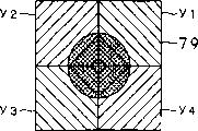
图13是说明图11所示光学头的其他光学系统中设置的复合光学元件内的分割棱镜的透视图。FIG. 13 is a perspective view illustrating split prisms in a composite optical element provided in another optical system of the optical head shown in FIG. 11. FIG.
图14是从返回光的入射面侧观看图11所示光学头的其他光学系统中设置的复合光学元件内的分割棱镜的图。FIG. 14 is a view of a split prism in a compound optical element provided in another optical system of the optical head shown in FIG. 11 viewed from the incident surface side of return light.
图15是图11所示光学头的其他光学系统中设置的受光部的主光束用光检测器及侧光束用光检测器的说明图。15 is an explanatory diagram of a main beam photodetector and a side beam photodetector provided in another optical system of the optical head shown in FIG. 11 .
图16是具有与图11所示光学头的其他光学系统中的复合光学元件具有的分割棱镜同等功能的光栅的平面图。16 is a plan view of a grating having a function equivalent to that of a split prism in a compound optical element in another optical system of the optical head shown in FIG. 11 .
图17A至17C表示入射图11所示光学头中的复合光学元件具有的分割棱镜的衍射光,图17A表示物镜靠近光盘的状态,图17B表示物镜位于聚焦位置的状态,图17C表示物镜远离光盘的状态。17A to 17C represent the diffracted light incident on the split prism that the composite optical element in the optical head shown in FIG. status.
图18A至18C表示图11所示光学头具有的主光束用光检测器的各受光区域的光束光斑,图18A表示物镜靠近光盘的状态,图18B表示物镜位于聚焦位置的状态,图18C表示物镜远离光盘的状态。18A to 18C show the beam spot of each light-receiving area of the main beam photodetector that the optical head shown in FIG. 11 has. away from the state of the disc.
图19是光盘装置具备的光学头中的其他光学系统的概略图。19 is a schematic diagram of another optical system in the optical head included in the optical disc device.
图20是图19所示光学头的其他光学系统中设置的2波长光源的发光点的说明图。FIG. 20 is an explanatory diagram of light emitting points of a two-wavelength light source provided in another optical system of the optical head shown in FIG. 19 .
图21是说明图19所示光学头的其他光学系统中设置的分割棱镜的透视图。FIG. 21 is a perspective view illustrating a split prism provided in another optical system of the optical head shown in FIG. 19. FIG.
图22说明是图19所示光学头的其他光学系统中设置的分割棱镜的侧面图。FIG. 22 illustrates a side view of a split prism provided in another optical system of the optical head shown in FIG. 19. FIG.
图23是图19所示光学头的其他光学系统中设置的受光部的主光束用光检测器及侧光束用光检测器的说明图。23 is an explanatory diagram of a main beam photodetector and a side beam photodetector provided in another optical system of the optical head shown in FIG. 19 in the light receiving unit.
图24A至24C表示入射图19所示光学头中的复合光学元件具有的分割棱镜的衍射光,图24A表示物镜靠近光盘的状态,图24B表示物镜位于聚焦位置的状态,图24C表示物镜远离光盘的状态。24A to 24C represent the diffracted light incident on the split prism that the composite optical element in the optical head shown in FIG. status.
图25A至25C至表示图19所示光学头具有的主光束用光检测器的各受光区域的光束光斑,图25A表示物镜靠近光盘的状态,图25B表示物镜位于聚焦位置的状态,图25C表示物镜远离光盘的状态。25A to 25C show the beam spot of each light-receiving area of the main beam photodetector that the optical head shown in FIG. 19 has. The state where the objective lens is far away from the disc.
图26是光盘装置具备的光学头中的其他光学系统的概略图。26 is a schematic diagram of another optical system in the optical head included in the optical disc device.
图27是光盘装置具备的光学头中的其他光学系统的概略图。27 is a schematic diagram of another optical system in the optical head included in the optical disc device.
图28是光盘装置具备的光学头中的其他光学系统的概略图。28 is a schematic diagram of another optical system in the optical head included in the optical disc device.
图29是光盘装置具备的光学头中的其他光学系统的概略图。29 is a schematic diagram of another optical system in the optical head included in the optical disc device.
图30是图29所示光学头的其他光学系统中设置的复合光学元件的透视图。Fig. 30 is a perspective view of a composite optical element provided in another optical system of the optical head shown in Fig. 29 .
图31是说明图29所示光学头的其他光学系统中设置的复合光学元件内的分割棱镜的透视图。FIG. 31 is a perspective view illustrating a split prism in a composite optical element provided in another optical system of the optical head shown in FIG. 29. FIG.
图32是从返回光的入射面侧观看图29所示光学头的其他光学系统中设置的复合光学元件内的分割棱镜的图。FIG. 32 is a view of a split prism in a composite optical element provided in another optical system of the optical head shown in FIG. 29 viewed from the incident surface side of return light.
图33是图29所示光学头的其他光学系统中设置的受光部的主光束用光检测器及侧光束用光检测器的说明图。33 is an explanatory diagram of a photodetector for a main beam and a photodetector for a side beam of a light receiving unit provided in another optical system of the optical head shown in FIG. 29 .
图34A至34C表示入射图29所示光学头中的复合光学元件具有的分割棱镜的衍射光,图34A表示物镜靠近光盘的状态,图34B表示物镜位于聚焦位置的状态,图34C表示物镜远离光盘的状态。34A to 34C represent the diffracted light of the split prism that the composite optical element in the optical head shown in Fig. 29 has, and Fig. 34A represents the state that the objective lens is close to the optical disc, and Fig. 34B represents the state that the objective lens is in the focus position, and Fig. 34C represents that the objective lens is away from the optical disc status.
图35A至35C至表示图29所示光学头具有的主光束用光检测器的各受光区域的光束光斑,图35A表示物镜靠近光盘的状态,图35B表示物镜位于聚焦位置的状态,图35C表示物镜远离光盘的状态。35A to 35C show the beam spot of each light-receiving area of the main beam photodetector that the optical head shown in FIG. 29 has. FIG. 35A shows the state where the objective lens is close to the optical disc. The state where the objective lens is far away from the disc.
图36是光盘装置具备的光学头中的其他光学系统的概略图。36 is a schematic diagram of another optical system in the optical head included in the optical disc device.
图37是光盘装置具备的光学头中的其他光学系统的概略图。37 is a schematic diagram of another optical system in the optical head included in the optical disc device.
图38是光盘装置具备的光学头中的其他光学系统的概略图。38 is a schematic diagram of another optical system in the optical head included in the optical disc device.
发明的最佳实施例Best Embodiment of the Invention
以下,参照图面说明应用本发明的光盘装置。Hereinafter, an optical disc device to which the present invention is applied will be described with reference to the drawings.
如图4所示,光盘装置1是诸如CD(Compact Disc:光盘)、DVD(Digital Versatile Disc:数字通用视盘)、可进行信息的追记的CD-R(Recordable:可刻录)、可进行信息的改写的CD-RW(ReWritable:可重写)等的光盘和磁光盘等,可以对光盘2执行信息的记录及/或再现(以下记述为记录再现。)。特别地,以下,说明光盘装置1采用CD或DVD作为光盘2,从这些CD或DVD进行信息的再现或记录的情况。As shown in FIG. 4, the optical disc device 1 is, for example, a CD (Compact Disc: optical disc), a DVD (Digital Versatile Disc: Digital Versatile Video Disc), a CD-R (Recordable: Recordable) that can record information, and a CD-R that can record information. Rewritable CD-RW (ReWritable: Rewritable) optical discs, magneto-optical discs, and the like can record and/or reproduce information on the optical disc 2 (hereinafter referred to as recording and reproducing). In particular, a case where the optical disc device 1 uses a CD or DVD as the optical disc 2 and reproduces or records information from the CD or DVD will be described below.
光盘装置1具备:从光盘2进行信息的记录再现的光学头3;旋转驱动光盘2的盘旋转驱动机构4;沿光盘2的径向移动光学头3的传送机构5;控制这些光学头3、盘旋转驱动机构4、传送机构5的控制部6。The optical disc device 1 is equipped with: an optical head 3 for recording and reproducing information from an optical disc 2; a disk rotation drive mechanism 4 for rotationally driving the optical disc 2; a transport mechanism 5 for moving the optical head 3 in the radial direction of the optical disc 2; controlling these optical heads 3, Disk rotation drive mechanism 4, controller 6 of transfer mechanism 5.
盘旋转驱动机构4具备载置光盘2的盘架7和旋转驱动该盘架7的主轴马达8。传送机构5具有(未图示)支持光学头3的支持基座、支持该支持基座使其可移动的主轴及副轴和使支持基座移动的滑轨马达。The disc rotation drive mechanism 4 includes a rack 7 on which the optical disc 2 is placed, and a spindle motor 8 that rotationally drives the rack 7 . The transport mechanism 5 has (not shown) a support base for supporting the optical head 3 , a main shaft and a sub-axis for movably supporting the support base, and a slide motor for moving the support base.
如图4所示,控制部6具有:存取控制电路9,驱动控制传送机构5并控制相对于光盘2的径向的光学头3的位置;伺服电路10,驱动控制光学头3的二轴执行器;驱动控制器11,控制这些存取控制电路9、伺服电路10和光学头3。另外,该控制部6具备:信号解调电路12,解调处理来自光学头3的信号;纠错电路13,对解调处理的信号进行纠错;接口14,用于将纠错后的信号向外部计算机等的电子设备输出。As shown in Figure 4, the control unit 6 has: an access control circuit 9, which drives and controls the transmission mechanism 5 and controls the position of the optical head 3 relative to the radial direction of the optical disc 2; a servo circuit 10, which drives and controls the two axes of the optical head 3 Actuator; drive controller 11 to control these access control circuit 9 , servo circuit 10 and optical head 3 . In addition, the control unit 6 has: a signal demodulation circuit 12, which demodulates and processes the signal from the optical head 3; an error correction circuit 13, which corrects the demodulated signal; an interface 14, which is used to convert the error-corrected signal Output to electronic equipment such as an external computer.
以上构成的光盘装置1,通过盘旋转驱动机构4的主轴马达8旋转驱动载置光盘2的盘架7,根据来自控制部6的存取控制电路9的控制信号驱动控制传送机构5,将光学头3移动到与光盘2的期望的记录轨道对应的位置,从而对光盘2进行信息的记录再现。The optical disc apparatus 1 of above-mentioned structure, by the spindle motor 8 of disc rotation driving mechanism 4, the disc holder 7 that places optical disc 2 is rotationally driven, and the transmission mechanism 5 is driven and controlled according to the control signal from the access control circuit 9 of the control unit 6, and the optical The head 3 moves to a position corresponding to a desired recording track on the optical disc 2 to record and reproduce information on the optical disc 2 .
这里,详细说明上述光学头3。Here, the above-mentioned optical head 3 will be described in detail.
如图5所示,光学头3例如具有从光盘2再现信息的光学系统30和驱动该光学系统30具有的后述物镜变位的透镜驱动机构(未图示)。As shown in FIG. 5 , the optical head 3 includes, for example, an optical system 30 for reproducing information from the optical disc 2 and a lens drive mechanism (not shown) for driving the displacement of an objective lens included in the optical system 30 , which will be described later.
光学头3具备的光学系统30,按照光路顺序,包括:受发光一体型元件31,由出射激光的光源和接受光盘2的返回光的受光元件一体形成;复合光学元件32,分割从该受发光一体型元件31出射的出射光,将来自光盘2的返回光与出射光分离;孔径光阑33,将从受发光一体型元件31出射并透过复合光学元件32的出射光收缩到规定的孔径数NA;2波长物镜34,将该孔径光阑33收缩的出射光会聚到光盘2的记录面2a。The optical system 30 that the optical head 3 possesses includes, according to the order of the light paths: an integrated light-receiving element 31, which is integrally formed by a light source for emitting laser light and a light-receiving element that receives the return light of the optical disc 2; The outgoing light emitted by the integrated element 31 separates the return light from the optical disc 2 from the outgoing light; the aperture stop 33 shrinks the outgoing light emitted from the integrated light-emitting element 31 and passed through the composite optical element 32 to a specified aperture. Number NA; 2 wavelengths objective lens 34 condenses the output light contracted by the aperture stop 33 onto the recording surface 2 a of the optical disc 2 .
受发光一体型元件31具备选择性出射波长为例如780nm左右的激光和波长为650nm左右的激光的半导体激光器和分割成受光区域的受光元件(其详细内容后述)。这里,在光盘2为CD格式的光盘时,受发光一体型元件31根据来自驱动控制器11的控制信号出射波长大致为780nm的激光,在光盘2为DVD格式的光盘时,根据来自驱动控制器11的控制信号,可切换成出射波长大致为650nm的激光。The integrated light-receiving element 31 includes a semiconductor laser that selectively emits laser light with a wavelength of about 780 nm and laser light with a wavelength of about 650 nm, and a light-receiving element divided into light-receiving regions (the details will be described later). Here, when the optical disc 2 is an optical disc in the CD format, the light-emitting integrated element 31 emits laser light with a wavelength of approximately 780 nm according to a control signal from the drive controller 11; The control signal of 11 can be switched to a laser with an emission wavelength of approximately 650nm.
如图5至图7所示,复合光学元件32例如通过树脂材料的射出成型而形成块状,具有靠近受发光一体型元件31并与从该受发光一体型元件31出射的出射光的光轴正交的第1面41和与该第1面41平行对置的第2面42。As shown in FIGS. 5 to 7 , the composite optical element 32 is formed into a block shape by, for example, injection molding of a resin material, and has an optical axis close to the integrated light-receiving element 31 and the outgoing light emitted from the integrated light-emitting element 31. The orthogonal first surface 41 and the second surface 42 parallel to the first surface 41 face each other.
第1面41设有第1衍射光栅45,将受发光一体型元件31出射的出射光分割成0次光及±1次光组成的3束光。光学系统30为了获得跟踪误差信号TE,采用所谓3光斑法(3光束法),通过受发光一体型元件31接受由第1衍射光栅45分割的±1次光,检测±1次光的各输出的差分,从而进行跟踪伺服。The first surface 41 is provided with a first diffraction grating 45 , which splits the emitted light emitted by the integrated light-receiving element 31 into three beams consisting of 0-order light and ±1-order light. In order to obtain the tracking error signal TE, the optical system 30 adopts the so-called 3-spot method (3-beam method), receives the ±1st order light divided by the first diffraction grating 45 through the receiving and emitting unit 31, and detects each output of the ±1st order light The difference, so as to perform tracking servo.
第2面42设有第2衍射光栅46,使来自光盘2的各返回光中由第1衍射光栅45分割的0次光及±1次光衍射,分别再分割成0次光及±1次光,例如,将该+1次光作为返回光,与出射光的光路分离。The second surface 42 is provided with a second diffraction grating 46, which diffracts the 0-order light and ±1-order light divided by the first diffraction grating 45 in each return light from the optical disc 2, and then divides them into 0-order light and ±1-order light respectively. As for the light, for example, the +1st-order light is regarded as return light, and the optical path of the outgoing light is separated.
另外,第1面41设有第3衍射光栅47,其位于由第2衍射光栅46分离的返回光的光路上,使该返回光衍射,再分割成0次光及±1次光,将该-1次光例如导入受发光一体型元件31。该第3衍射光栅47与第1衍射光栅45配置在同一面内,且与其一侧相邻地配置。In addition, the first surface 41 is provided with a third diffraction grating 47, which is located on the optical path of the returned light separated by the second diffraction grating 46, diffracts the returned light, and divides it into 0-order light and ±1-order light. The -primary light is guided to, for example, the integrated light-emitting element 31 . The third diffraction grating 47 is disposed on the same plane as the first diffraction grating 45 and adjacent to one side thereof.
另外,复合光学元件32通过使由第2衍射光栅46分离的返回光通过,向入射第3衍射光栅47的返回光赋予规定量的象散。复合光学元件32通过调动受发光一体型元件31出射的出射光的光轴方向的位置,可容易地调整对光盘2的散焦。In addition, the composite optical element 32 imparts a predetermined amount of astigmatism to the returned light incident on the third diffraction grating 47 by passing the returned light separated by the second diffraction grating 46 . The composite optical element 32 can easily adjust the defocus of the optical disc 2 by adjusting the position in the direction of the optical axis of the emitted light emitted by the integrated light-emitting element 31 .
复合光学元件32如上述通过树脂材料的射出成型而形成。另外,作为其他形成方法,上述的第1衍射光栅45、第2衍射光栅46及第3衍射光栅47可通过刻蚀加工形成,也可通过机械加工形成。另外,作为形成复合光学元件32的材料,不限于树脂材料,也可采用硝化材料等具有透光性的光学材料,而且可以通过这些光学材料的组合,部分地改变材料构成。The composite optical element 32 is formed by injection molding of a resin material as described above. In addition, as another forming method, the above-mentioned first diffraction grating 45, second diffraction grating 46, and third diffraction grating 47 may be formed by etching or may be formed by machining. In addition, the material forming the composite optical element 32 is not limited to a resin material, and optical materials having light transmission properties such as nitrated materials can also be used, and the material configuration can be partially changed by combining these optical materials.
另外,复合光学元件32也可设计成内部具有反射面,利用反射面使光路弯曲,从而可以提高光学设计的自由度。In addition, the composite optical element 32 can also be designed to have a reflective surface inside, and the optical path can be bent by using the reflective surface, so that the degree of freedom of optical design can be improved.
这里,说明复合光学元件32内,受发光一体型元件31出射的出射光的波长变动引起来自光盘2的返回光中发生光路变动的情况。Here, in the composite optical element 32 , the case where the wavelength fluctuation of the outgoing light emitted from the integrated light-receiving element 31 causes the optical path fluctuation in the return light from the optical disc 2 will be described.
如图7所示,复合光学元件32通过第2衍射光栅46将来自光盘2的返回光L衍射成+1次光,与出射光的光路分离,并通过第3衍射光栅47将由第2衍射光栅46进行了光路分离的返回光L衍射为-1次光,导入受发光一体型元件31。As shown in FIG. 7 , the composite optical element 32 diffracts the return light L from the optical disc 2 into a +1st order light through the second diffraction grating 46 to separate from the optical path of the outgoing light, and passes through the third diffraction grating 47 to convert the return light L from the optical disc 2 to the +1st order light, and passes through the third diffraction grating 47. 46 The return light L whose optical paths have been separated is diffracted into −1st order light, and is introduced into the integrated light-emitting element 31 .
这里,如图8所示,复合光学元件32内,若令返回光的波长为λ,第2衍射光栅46中的衍射角为θ1,第3衍射光栅47中的衍射角为θ2,第2衍射光栅46的光栅常数为d1,第3衍射光栅47的光栅常数为d2,第2衍射光栅46中的衍射次数为+1,第3衍射光栅47中的衍射次数为-1,第2衍射光栅46和第3衍射光栅47之间的媒质的折射率为n,即形成复合光学元件32的树脂材料的折射率为n,则通过式3可导出以下的式8及式9。Here, as shown in FIG. 8, in the composite optical element 32, if the wavelength of the return light is λ, the diffraction angle in the second diffraction grating 46 is θ 1 , the diffraction angle in the third diffraction grating 47 is θ 2 , and the diffraction angle in the second diffraction grating 47 is θ 2 . 2. The grating constant of the diffraction grating 46 is d1 , the grating constant of the third diffraction grating 47 is d2 , the order of diffraction in the second diffraction grating 46 is +1, the order of diffraction in the third diffraction grating 47 is -1, and the order of diffraction in the third diffraction grating 47 is -1. 2 The refractive index of the medium between the diffraction grating 46 and the third diffraction grating 47 is n, that is, the refractive index of the resin material forming the composite optical element 32 is n, and the following equations 8 and 9 can be derived from equation 3.
n·sinθ1=λ/d1····(8)n·sinθ 1 =λ/d 1 ····(8)
sinθ2-n·sinθ1=-λ/d2····(9)sinθ 2 -n sinθ 1 = -λ/d 2 ····(9)
接着,通过式8及式9,sinθ1及sinθ2可用以下的式10及式11表达。Next, from Equation 8 and Equation 9, sinθ1 and sinθ2 can be expressed by Equation 10 and Equation 11 below.
sinθ1=λ/(d1·n)····(1 0)sinθ 1 =λ/(d 1 ·n)····(1 0)
sinθ2=λ·(1/d1-1/d2)····(11)sinθ 2 =λ·(1/d 1 -1/d 2 )····(11)
接着,通过式10及式11,cosθ1及cosθ2可用以下的式12及式13表达。Next, from Equation 10 and Equation 11, cosθ1 and cosθ2 can be expressed by Equation 12 and Equation 13 below.
cosθ1=(1-λ2/(d1·n)2)1/2····(12)cosθ 1 =(1-λ 2 /(d 1 ·n) 2 ) 1/2 ····(12)
cosθ2=(1-λ2·(1/d1-1/d2)2)1/2····(13)cosθ 2 =(1-λ 2 ·(1/d 1 -1/d 2 ) 2 ) 1/2 ····(13)
接着,若取以第2面42为x=0并从第2面42垂直到第1面41侧的方向为x轴,取将从该x轴垂直偏转后的方向为y轴,取由第2衍射光栅46衍射成+1次光的来自光盘2的返回光中由第1衍射光栅45衍射成0次光的主光束为光线l1,则该光线l1的光路可以用以下的式14表示。Next, if the second surface 42 is taken as x=0 and the direction perpendicular to the first surface 41 from the second surface 42 is taken as the x-axis, and the direction deflected vertically from the x-axis is taken as the y-axis, 2. Among the returning light from the optical disc 2 diffracted by the diffraction grating 46 into the +1st order light, the main beam diffracted by the first diffraction grating 45 into the 0th order light is the light 11 , and the optical path of the light 11 can be expressed by the following formula 14 express.
y=tanθ1·x····(14)y=tanθ 1 ·x····(14)
接着,若令第1面41和第2面42的间隔为a,则光线l1和第1面41交差即入射第3衍射光栅47的位置可用以下的式15表示。Next, if the distance between the first surface 41 and the second surface 42 is a, the position where the light 11 intersects with the first surface 41, that is, enters the third diffraction grating 47 can be expressed by the following formula 15.
x=a,y=a·tanθ1····(15)x=a, y=a·tanθ 1 ····(15)
从而,若令由第3衍射光栅47衍射成-1次光的返回光为光线l2,该光线l2的光路可用以下的式16表示。Therefore, if the return light diffracted by the third diffraction grating 47 into -1st order light is the light ray l 2 , the optical path of the light ray l 2 can be expressed by the following formula 16.
y=tanθ2·x+a(tanθ1-tanθ2)····(16)y=tanθ 2 ·x+a(tanθ 1 -tanθ 2 )····(16)
接着,令光线l2和x轴交差的点为B,B点的位置可用以下的式17表示。Next, let the point where the ray 12 intersects the x-axis be B, and the position of the point B can be represented by the following formula 17.
x=a(1-tanθ1/tanθ2),y=0····(17)x=a(1-tanθ 1 /tanθ 2 ), y=0····(17)
通过式17可明白x轴上的位置x取决于第2衍射光栅46的衍射角θ1。由于衍射角θ1是式8中波长λ的函数,因而在上述例的场合,λ若变化,则衍射角θ1变化,B点的坐标变化,由于出射光的波长变动导致受发光一体型元件31的受光区域的光束光斑的位置变化。From Equation 17, it can be understood that the position x on the x-axis depends on the diffraction angle θ 1 of the second diffraction grating 46 . Since the diffraction angle θ1 is a function of the wavelength λ in Formula 8, in the above example, if λ changes, the diffraction angle θ1 changes, and the coordinates of point B change. The position of the beam spot in the light receiving area of 31 changes.
从而,由于受发光一体型元件31的受光区域的光束光斑的位置与波长变动无关而成为一定,若将表示式17的x的式的右边第2项采用式17至式20以λ表示,则可表示成以下的式18。Therefore, since the position of the beam spot in the light-receiving region of the integrated light-receiving element 31 is constant regardless of wavelength variation, if the second term on the right side of the expression x in Expression 17 is expressed by λ using Expressions 17 to 20, then It can be expressed as the following formula 18.
若令d2<d1,If let d 2 <d 1 ,
tanθ1/tanθ2=(sinθ1/cosθ1)/(sinθ2/cosθ2)tanθ 1 /tanθ 2 =(sinθ 1 /cosθ 1 )/(sinθ 2 /cosθ 2 )
=-((d1 2d2 2/(d2-d1)2-λ2)/(n2d1 2-λ2))1/2····(18)=-((d 1 2 d 2 2 /(d 2 -d 1 ) 2 -λ 2 )/(n 2 d 1 2 -λ 2 )) 1/2 ····(18)
这里,若式18例如代入以下的式19所示的条件并整理,则可表示成以下的式20。Here, Equation 18 can be expressed as Equation 20 below, for example, by substituting and organizing the conditions shown in Equation 19 below.
(n+1)d2=nd1····(19)(n+1)d 2 =nd 1 ····(19)
tanθ1/tanθ2=-1····(20)tanθ 1 /tanθ 2 = -1····(20)
通过式19及式20,可明白第3衍射光栅47的B点的x坐标与λ无关而成为一定。From Equation 19 and Equation 20, it can be seen that the x-coordinate of point B of the third diffraction grating 47 is constant regardless of λ.
即,例如,设计复合光学元件32使第2衍射光栅46的光栅常数d1和第3衍射光栅47的光栅常数d2满足式19,从而,即使波长变动,受发光一体型元件31的受光区域中的光束光斑的位置也可保持一定。That is, for example, the composite optical element 32 is designed so that the grating constant d1 of the second diffraction grating 46 and the grating constant d2 of the third diffraction grating 47 satisfy the formula 19, so that even if the wavelength changes, the light-receiving region of the integrated light-receiving element 31 The position of the beam spot can also be kept constant.
这样,复合光学元件32,例如通过确定第2衍射光栅46的光栅常数d1和第3衍射光栅47的光栅常数d2,当由受发光一体型元件31出射的出射光的波长变动导致来自光盘2的返回光在第2衍射光栅46作为+1次光衍射而与出射光分离时,即使该分离的返回光的光路变动,通过使该返回光在第3衍射光栅47作为-1次光衍射,也能够使来自光盘2的返回光总是适当地导入受发光一体型元件31的受光区域的规定的位置。In this way, the composite optical element 32, for example, by determining the grating constant d1 of the second diffraction grating 46 and the grating constant d2 of the third diffraction grating 47, when the wavelength fluctuation of the emitted light emitted by the integrated light-emitting element 31 causes When the return light of 2 is separated from the outgoing light as +1 order light diffraction by the second diffraction grating 46, even if the optical path of the separated return light varies, the return light is diffracted by the third diffraction grating 47 as -1 order light. Therefore, the return light from the optical disc 2 can always be properly guided to a predetermined position of the light receiving region of the integrated light emitting device 31 .
孔径光阑33配置在通过复合光学元件32的第2衍射光栅46的出射光的光轴上。The aperture stop 33 is arranged on the optical axis of the outgoing light passing through the second diffraction grating 46 of the composite optical element 32 .
2波长物镜34是与从受发光一体型元件31出射的相互不同波长的激光对应的会聚透镜,由至少1个凸透镜构成,设置成将从受发光一体型元件31出射并由孔径光阑33收缩的出射光会聚到光盘2。The 2-wavelength objective lens 34 is a converging lens corresponding to the laser beams of different wavelengths emitted from the integrated light-receiving element 31, and is composed of at least one convex lens. The outgoing light converges to disc 2.
如图9所示,受发光一体型元件31包括:接受由第1衍射光栅45分割的0次光即主光束的大致方形状的主光束用光检测器51和分别接受由第1衍射光栅45分割的±1次光即2个侧光束的一组大致带状的侧光束用光检测器52、53。受发光一体型元件31配置成与由复合光学元件32的第3衍射光栅47补正了光路变动的返回光入射的位置对应。受发光一体型元件31在中央位置配置大致方形状的主光束用光检测器51,同时在该主光束用光检测器51的两侧以一定间隔分别配置一组大致带状的侧光束用光检测器52、53。As shown in FIG. 9 , the integrated light-emitting element 31 includes: a roughly square-shaped main beam photodetector 51 that receives the 0-order light divided by the first diffraction grating 45, that is, the main beam; A set of substantially strip-shaped side beam photodetectors 52 and 53 for the divided ±1-order light, that is, two side beams. The integrated light-receiving element 31 is disposed so as to correspond to the incident position of the return light whose optical path variation is corrected by the third diffraction grating 47 of the composite optical element 32 . The photodetector 51 for the main beam with a substantially square shape is arranged in the central position of the integrated light-emitting element 31, and a group of photodetectors 51 for the side beam in the shape of a substantially strip are respectively arranged at a certain interval on both sides of the photodetector 51 for the main beam. Detectors 52,53.
另外,如图9所示,受发光一体型元件31的主光束用光检测器51具有由相互正交的一组分割线4等分的各受光区域a1、b1、c1、d1。由第3衍射光栅47补正了光路变动的返回光入射这些各受光区域a1、b1、c1、d1。In addition, as shown in FIG. 9 , the photodetector 51 for the main beam of the integrated light-receiving and light-emitting element 31 has light-receiving areas a 1 , b 1 , c 1 , and d 1 equally divided by a set of four dividing lines perpendicular to each other. . The return light whose optical path variation has been corrected by the third diffraction grating 47 enters these light receiving regions a 1 , b 1 , c 1 , and d 1 .
光学头3具备的透镜驱动机构包括(未图示):保持2波长物镜34的透镜支架;支持该透镜支架使其能够在与2波长物镜34的光轴平行的聚焦方向及与2波长物镜34的光轴正交的跟踪方向的二轴方向上变位的支架支持部件;在二轴方向通过电磁力驱动移动透镜支架的电磁驱动部。The lens driving mechanism that optical head 3 possesses comprises (not shown): hold the lens holder of 2 wavelength objective lens 34; The bracket support member that displaces in the two-axis direction of the tracking direction orthogonal to the optical axis; the electromagnetic drive part that moves the lens bracket by electromagnetic force in the two-axis direction.
透镜驱动机构根据受发光一体型元件31的主光束用光检测器51检测的聚焦误差信号及侧光束用光检测器52、53检测的跟踪误差信号,在聚焦方向及跟踪方向分别驱动移动2波长物镜34,将出射光聚焦到光盘2的记录面2a的记录轨道。Based on the focus error signal detected by the photodetector 51 for the main beam and the tracking error signals detected by the photodetectors 52 and 53 for the side beam of the integrated light-receiving element 31, the lens drive mechanism drives and moves by 2 wavelengths in the focusing direction and the tracking direction respectively. The objective lens 34 focuses the outgoing light onto the recording track on the recording surface 2 a of the optical disc 2 .
另外,复合光学元件32中,第1衍射光栅45、第2衍射光栅46及第3衍射光栅47可分别通过刻蚀处理等以规定的全息图图案形成为全息图元件。另外,采用全息图元件时,最好采用表面浮雕型全息图,另外,也可采用闪耀全息图,以提高衍射效率。In addition, in the composite optical element 32, the first diffraction grating 45, the second diffraction grating 46, and the third diffraction grating 47 can be respectively formed as a hologram element with a predetermined hologram pattern by etching or the like. In addition, when a hologram element is used, it is preferable to use a surface relief type hologram. In addition, a blazed hologram may also be used to improve the diffraction efficiency.
以上构成的光盘装置1中,根据光学头3从来自光盘2的返回光检测的聚焦误差信号及跟踪误差信号,从伺服电路10向光学头3的二轴执行器输出控制信号,在聚焦方向及跟踪方向分别驱动移动2波长物镜34,从而,出射光经由2波长物镜34聚焦到光盘2的期望的记录轨道。光盘装置1中,由光学头3读取的信号通过信号解调电路12及纠错电路13进行解调处理及纠错处理后,从接口14作为再现信号输出。In the optical disc device 1 configured as above, based on the focus error signal and the tracking error signal detected by the optical head 3 from the return light from the optical disc 2, control signals are output from the servo circuit 10 to the two-axis actuator of the optical head 3, and the focus direction and The two-wavelength objective lens 34 is driven and moved in the tracking direction, so that the emitted light is focused on a desired recording track of the optical disc 2 via the two-wavelength objective lens 34 . In the optical disc device 1, the signal read by the optical head 3 is demodulated and corrected by the signal demodulation circuit 12 and the error correction circuit 13, and then output as a reproduced signal from the interface 14.
这里,就光盘装置1参照图面说明光学头3内的出射光及返回光的光路。Here, the optical path of the outgoing light and the returning light in the optical head 3 will be described with reference to the drawings for the optical disc device 1 .
光盘装置1从光盘2的记录面2a再现信息的场合,如图5所示,从受发光一体型元件31出射的出射光由复合光学元件32的第1衍射光栅45分别分割成由0次光及±1次光组成的3光束。分割成3光束的出射光透过复合光学元件32的第2衍射光栅46,由2波长物镜34分别会聚到光盘2的记录面2a。When the optical disc device 1 reproduces information from the recording surface 2a of the optical disc 2, as shown in FIG. And ± 1 light composed of 3 beams. The outgoing light split into three light beams passes through the second diffraction grating 46 of the composite optical element 32 and is converged by the two-wavelength objective lens 34 on the recording surface 2 a of the optical disc 2 .
来自光盘2的记录面2a的返回光由复合光学元件32的第2衍射光栅46衍射,分割成0次光及±1次光,该+1次光作为返回光与出射光分离并入射第3衍射光栅47。入射第3衍射光栅47的返回光由第3衍射光栅47衍射,再分割成0次光及±1次光,该-1次光作为返回光分别入射受发光一体型元件31的主光束用光检测器51的各受光区域a1、b1、c1、d1。The return light from the recording surface 2a of the optical disc 2 is diffracted by the second diffraction grating 46 of the composite optical element 32, and is divided into 0-order light and ±1-order light. Diffraction grating 47 . The return light incident on the third diffraction grating 47 is diffracted by the third diffraction grating 47, and then divided into zero-order light and ±1-order light. The light receiving regions a 1 , b 1 , c 1 , and d 1 of the detector 51 .
这里,复合光学元件32内,第2衍射光栅46中发生的返回光的光路变动由第3衍射光栅47补正,返回光适当入射受发光一体型元件31的主光束用光检测器51的各受光区域a1、b1、c1、d1。Here, in the composite optical element 32, the optical path variation of the return light generated in the second diffraction grating 46 is corrected by the third diffraction grating 47, and the return light is appropriately incident on each receiving light of the main beam photodetector 51 of the integrated light-receiving element 31. Area a 1 , b 1 , c 1 , d 1 .
这里,若相对于光盘2的记录面2a,2波长物镜34处于最佳位置,相对于光盘2的记录面2a聚焦即所谓精确聚焦的状态,则入射主光束用光检测器51的各受光区域a1、b1、c1、d1的返回光形成的光束光斑的形状成为图10B所示的圆形。Here, if the 2-wavelength objective lens 34 is at the optimum position with respect to the recording surface 2a of the optical disc 2, and is focused with respect to the recording surface 2a of the optical disc 2, that is, in a state of so-called precise focus, each light-receiving area of the photodetector 51 for incident main beam The shape of the beam spot formed by the returning light of a 1 , b 1 , c 1 , and d 1 is circular as shown in FIG. 10B .
另外,若为图10B所示圆形的光束光斑的场合,主光束用光检测器51中,分别对置的各受光区域a1、c1和各受光区域b1、d1的各受光量成为相等。In addition, in the case of a circular beam spot as shown in FIG. 10B , in the photodetector 51 for the main beam, the received light amounts of the respective opposing light receiving areas a 1 , c 1 and the respective light receiving areas b 1 , d 1 become equal.
但是,物镜32过于靠近光盘2的记录面2a的场合,从精确聚焦的状态偏离,由于由第2衍射光栅46分离的返回光通过复合光学元件32而发生的象散,入射主光束用光检测器51的各受光区域a1、b1、c1、d1的返回光形成的光束光斑的形状成为如图10A所示其长轴跨越受光区域a1及受光区域c1的椭圆形状。However, when the objective lens 32 is too close to the recording surface 2a of the optical disc 2, it deviates from the state of precise focus, and due to the astigmatism that occurs when the return light separated by the second diffraction grating 46 passes through the composite optical element 32, the incident main beam is detected by light. The shape of the beam spot formed by the return light of each light receiving area a 1 , b 1 , c 1 , d 1 of the device 51 is an ellipse whose major axis crosses the light receiving area a 1 and the light receiving area c 1 as shown in FIG. 10A .
而且,2波长物镜34过于远离光盘2的记录面2a的场合,从精确聚焦的状态偏离,由于由第2衍射光栅46分离的返回光通过复合光学元件32而发生的象散,入射主光束用光检测器51的各受光区域a1、b1、c1、d1的返回光形成的光束光斑的形状成为如图10C所示其长轴跨越受光区域b1及受光区域d1的椭圆形状,是与上述图10A所示光束光斑的形状相比其长轴方向倾斜了90度的椭圆形状。Moreover, when the 2-wavelength objective lens 34 is too far away from the recording surface 2a of the optical disc 2, it deviates from the state of precise focus, and due to the astigmatism that occurs when the return light separated by the second diffraction grating 46 passes through the composite optical element 32, the incident main beam The shape of the beam spot formed by the return light of each light receiving area a 1 , b 1 , c 1 , and d 1 of the photodetector 51 is an ellipse whose major axis crosses the light receiving area b 1 and the light receiving area d 1 as shown in FIG. 10C , is an elliptical shape in which the major axis direction is inclined by 90 degrees compared with the shape of the beam spot shown in FIG. 10A described above.
因而,若为图10A及图10B所示椭圆形状的光束光斑的场合,主光束用光检测器51的相互对置的二组各受光区域a1、c1和各受光区域b1、d1中,一个组的各受光区域受光的受光量变多,同时另一个组的各受光区域受光的受光量变少。Therefore, in the case of an elliptical beam spot as shown in FIG. 10A and FIG. 10B , the two groups of the photodetectors 51 for the main beam facing each other each of the light receiving areas a 1 , c 1 and the respective light receiving areas b 1 , d 1 In this case, the amount of light received by each light-receiving region of one group increases, while the amount of light received by each light-receiving region of the other group decreases.
从而,若令主光束用光检测器51中各受光区域a1、b1、c1、d1分别检测的各输出为Sa1、Sb1、Sc1、Sd1,则聚焦误差信号FE可用以下所示式21计算。Therefore, if the outputs detected by the light-receiving regions a 1 , b 1 , c 1 , and d 1 in the photodetector 51 for the main beam are Sa 1 , Sb 1 , Sc 1 , and Sd 1 , the focus error signal FE can be used Calculated by Equation 21 shown below.
FE=(Sa1+Sc1)-(Sb1+Sd1)····(21)FE=(Sa 1 +Sc 1 )-(Sb 1 +Sd 1 )····(21)
即,主光束用光检测器51中,相对于光盘2的记录面2a,2波长物镜34位于聚焦位置的场合,由式21运算的聚焦误差信号FE成为0。另外,主光束用光检测器51中,2波长物镜34过于靠近光盘2的记录面2a的场合,聚焦误差信号FE成为正,另外2波长物镜34过于远离光盘2的记录面2a的场合,聚焦误差信号FE成为负。That is, when the two-wavelength objective lens 34 is at the focus position with respect to the recording surface 2a of the optical disc 2 in the main beam photodetector 51, the focus error signal FE calculated by Equation 21 becomes zero. In addition, in the main beam photodetector 51, when the 2-wavelength objective lens 34 is too close to the recording surface 2a of the optical disc 2, the focus error signal FE becomes positive, and when the 2-wavelength objective lens 34 is too far from the recording surface 2a of the optical disc 2, the focusing The error signal FE becomes negative.
如上所述,受发光一体型元件31的主光束用光检测器51,通过分别入射各受光区域a1、b1、c1、d1的各光束光斑的输出,可获得聚焦误差信号FE以及再现信号。As described above , the photodetector 51 for the main beam of the integrated light-receiving element 31 can obtain the focus error signal FE and reproduce the signal.
另外,一组各侧光束用光检测器52、53中,使由第1衍射光栅45分割成±1次光的侧光束由光盘2反射而成为返回光,在第2衍射光栅46中作为+1次光与出射光分离,由第3衍射光栅47补正光路变动后入射,通过检测各受光区域的各受光量并计算这些±1次光的各输出的差分,可获得跟踪误差信号TE。In addition, in a set of photodetectors 52 and 53 for each side beam, the side beams divided into ±1st-order light by the first diffraction grating 45 are reflected by the optical disc 2 and become return light, which is used as + in the second diffraction grating 46. The primary light is separated from the outgoing light, and the third diffraction grating 47 corrects the fluctuation of the optical path before it enters. By detecting the received light amount of each light receiving area and calculating the difference between the outputs of these ± primary lights, the tracking error signal TE can be obtained.
另外,如图11所示,光学头3例如具有:再现来自光盘2信息的光学系统60;使该光学系统60具有的后述的物镜驱动移动的未图示的透镜驱动机构。以下,说明具有光学系统60光学头3的构成例,其与具有光学系统30的光学头3大致相同的构成附上相同符号,其说明省略。In addition, as shown in FIG. 11 , the optical head 3 includes, for example, an optical system 60 for reproducing information from the optical disc 2 , and an unillustrated lens drive mechanism for driving and moving an objective lens included in the optical system 60 , which will be described later. Hereinafter, an example of the configuration of the optical head 3 having the optical system 60 will be described, and the configurations substantially the same as those of the optical head 3 having the optical system 30 will be denoted by the same reference numerals, and the description thereof will be omitted.
光学头3具有的光学系统60,按照光路顺序具备:选择向光盘2出射相互不同波长的激光的2波长光源61;将该2波长光源61出射的出射光分割,将来自光盘2的返回光与出射光分离,同时将与出射光分离的返回光再分割的复合光学元件62;将从2波长光源61出射并透过复合光学元件62的出射光收缩到规定的孔径数NA的孔径光阑33;将该孔径光阑33收缩的出射光会聚到光盘2的记录面2a的2波长物镜34;接受来自光盘2的返回光的受光部63。另外,光学系统60具有:在2波长光源61和复合光学元件62之间遮挡出射光中的有效光束以外的不必要光束的第1遮挡板64和在复合光学元件62和受光部63之间遮挡返回光中的有效光束以外的不必要光束的第2遮挡板65。The optical system 60 that the optical head 3 has has in accordance with the order of the optical paths: select the 2-wavelength light source 61 that emits laser light with different wavelengths to the optical disc 2; The composite optical element 62 that separates the outgoing light and divides the returning light separated from the outgoing light; the aperture stop 33 that shrinks the outgoing light emitted from the 2-wavelength light source 61 and passed through the composite optical element 62 to a specified number of apertures NA ; the 2-wavelength objective lens 34 that converges the outgoing light that has been contracted by the aperture stop 33 to the recording surface 2 a of the optical disc 2 ; In addition, the optical system 60 has: a first blocking plate 64 for blocking unnecessary light beams other than effective light beams in outgoing light between the two-wavelength light source 61 and the composite optical element 62; The second blocking plate 65 for unnecessary light beams other than the effective light beams in the return light.
2波长光源61具有可选择从发光点61a和发光点61b分别出射波长为例如780nm左右的激光和波长为例如650nm左右的激光的半导体激光器。这里,2波长光源61可进行如下切换,即在光盘2为CD格式的光盘时,根据驱动控制器11的控制信号,出射波长大致780nm的激光,当光盘2为DVD格式的光盘时,根据驱动控制器11的控制信号,出射波长大致650nm的激光。The two-wavelength light source 61 includes a semiconductor laser capable of selectively emitting laser light with a wavelength of, for example, about 780 nm and laser light with a wavelength of, for example, about 650 nm from the light emitting point 61 a and the light emitting point 61 b respectively. Here, the two-wavelength light source 61 can be switched as follows, that is, when the optical disc 2 is an optical disc in the CD format, it emits laser light with a wavelength of approximately 780 nm according to the control signal of the drive controller 11; The control signal of the controller 11 emits laser light with a wavelength of approximately 650 nm.
复合光学元件62如图11及图12所示,例如通过树脂材料的射出成型形成块状,具有:靠近2波长光源61并与该2波长光源61的发光点61a或发光点61b出射的出射光的光轴正交的第1面81;与该第1面81平行对置的第2面82;相对于第2面82倾斜规定的角度而对置的第3面83;相对于第1面81及第2面82垂直且相对于第3面83倾斜规定的角度而对置的第4面84。As shown in FIG. 11 and FIG. 12 , the compound optical element 62 is formed into a block shape by, for example, injection molding of a resin material, and has output light that is close to the two-wavelength light source 61 and emitted from the light-emitting point 61 a or light-emitting point 61 b of the two-wavelength light source 61 . The first surface 81 perpendicular to the optical axis of the first surface 81; the second surface 82 parallel to the first surface 81; the third surface 83 opposite to the second surface 82 at a predetermined angle; 81 and the second surface 82 are perpendicular to the fourth surface 84 facing the third surface 83 inclined at a predetermined angle.
第1面81设有将2波长光源61的发光点61a或发光点61b出射的出射光分割成0次光及±1次光组成的3光束的第1衍射光栅75。光学系统60为了获得跟踪误差信号TE,构成采用所谓3光斑法(3光束法),用受光部63接受由第1衍射光栅75分割的±1次光,检测±1次光的各输出的差分,从而进行跟踪伺服。The first surface 81 is provided with a first diffraction grating 75 that divides the emitted light emitted from the light emitting point 61 a or the light emitting point 61 b of the two-wavelength light source 61 into three light beams consisting of 0-order light and ±1-order light. The optical system 60 adopts the so-called 3-spot method (3-beam method) in order to obtain the tracking error signal TE. The light receiving unit 63 receives the ±1st-order light divided by the first diffraction grating 75, and detects the difference of the outputs of the ±1st-order light. , so as to perform tracking servo.
第2面82设有第2衍射光栅76,将来自光盘2的各返回光中由第1衍射光栅75分割的0次光及±1次光衍射,分别再分割成0次光及±1次光,例如,将该+1次光作为返回光与出射光的光路分离。The second surface 82 is provided with a second diffraction grating 76, which diffracts the 0-order light and ±1-order light divided by the first diffraction grating 75 in each return light from the optical disc 2, and divides them into 0-order light and ±1-order light respectively. As for the light, for example, the +1st order light is separated from the light path of the outgoing light as return light.
第3面83设有第3衍射光栅77,它位于由第2衍射光栅76分离的返回光的光路上,将该返回光反射及衍射,再分割0次光及±1次光,例如将该-1次光作为返回光,补正在第2衍射光栅76中发生的光路变动。The 3rd surface 83 is provided with the 3rd diffraction grating 77, and it is positioned on the optical path of the return light separated by the 2nd diffraction grating 76, reflects and diffracts this return light, divides 0 order light and ± 1 order light again, for example the The -primary light is used as return light to correct the optical path variation that occurs in the second diffraction grating 76 .
该第3衍射光栅77在第3面83上设有规定的反射膜,使入射的返回光全反射,起所谓反射型的衍射光栅的功能。The third diffraction grating 77 is provided with a predetermined reflective film on the third surface 83 to totally reflect the incident returning light, and functions as a so-called reflective diffraction grating.
第4面84设有分割棱镜78,位于由第3衍射光栅77补正了光路变动的返回光的光路上,将该返回光分割成4束。The fourth surface 84 is provided with a split prism 78 positioned on the optical path of the return light whose optical path variation has been corrected by the third diffraction grating 77, and divides the return light into four beams.
该分割棱镜78如图13及图14所示,形成大致正四角锥形状,配置成使由第3衍射光栅77反射及衍射的-1次光在该衍射光的焦点或焦点附近,衍射光的中心入射正四角锥的顶角的中心。As shown in FIGS. 13 and 14, the split prism 78 is substantially in the shape of a regular quadrangular pyramid, and is arranged so that the −1st order light reflected and diffracted by the third diffraction grating 77 is at or near the focal point of the diffracted light, and the diffracted light Central incidence The center of the corners of a regular quadrangular pyramid.
另外,分割棱镜78位于复合光学元件62的内侧,该内侧设置成朝向顶角。即,分割棱镜78配置成使由第1衍射光栅75分割的3光束中的0次光由第2衍射光栅76衍射,由第3衍射光栅77反射及衍射,再入射顶角。另外,分割棱镜78中,正四角锥的底面配置成与由第3衍射光栅77反射及衍射的-1次光的光轴正交。In addition, the split prism 78 is located on the inner side of the composite optical element 62 , the inner side being disposed toward the apex corner. That is, the dividing prism 78 is arranged so that the 0th order light among the three light beams divided by the first diffraction grating 75 is diffracted by the second diffraction grating 76, reflected and diffracted by the third diffraction grating 77, and re-enters the apex. In addition, in the split prism 78 , the bottom surface of the regular quadrangular pyramid is arranged so as to be perpendicular to the optical axis of the −1st order light reflected and diffracted by the third diffraction grating 77 .
另外,复合光学元件62使由第2衍射光栅76分离的返回光通过,从而向入射分割棱镜78的返回光赋予规定量的象散。复合光学元件62通过调动从2波长光源61选择出射的出射光的光轴方向的位置,可容易地调整对光盘2的散焦。In addition, the composite optical element 62 passes the return light separated by the second diffraction grating 76 , thereby imparting a predetermined amount of astigmatism to the return light entering the split prism 78 . The composite optical element 62 can easily adjust the defocus of the optical disc 2 by adjusting the position in the direction of the optical axis of the emitted light selectively emitted from the two-wavelength light source 61 .
复合光学元件62通过如上所述树脂材料的射出成型形成。另外,作为其他形成方法,可以通过刻蚀加工形成上述的第1衍射光栅75、第2衍射光栅76、第3衍射光栅77及分割棱镜78,也可以通过机械加工形成。另外,形成复合光学元件62的材料不限于树脂材料,也可采用硝化材料等的透光性光学材料,而且也可以通过这些光学材料的组合,部分地改变材料构成。The composite optical element 62 is formed by injection molding of a resin material as described above. In addition, as another forming method, the above-mentioned first diffraction grating 75, second diffraction grating 76, third diffraction grating 77, and split prism 78 may be formed by etching or may be formed by machining. In addition, the material forming the composite optical element 62 is not limited to the resin material, and light-transmitting optical materials such as nitrified materials may be used, and the material configuration may be partially changed by combining these optical materials.
这里,与用复合光学元件32说明的场合同样,例如,通过计算第2衍射光栅76及第3衍射光栅77的光栅常数和第3面83和第2面82形成的角度等来设计复合光学元件62,可补正波长变动引起的返回光的光路变动,将该返回光正确导入分割棱镜78的顶角。Here, as in the case of the composite optical element 32, for example, the composite optical element is designed by calculating the grating constants of the second diffraction grating 76 and the third diffraction grating 77 and the angle formed by the third surface 83 and the second surface 82, etc. 62 , the optical path variation of the returning light caused by the wavelength variation can be corrected, and the returning light can be correctly guided into the apex angle of the split prism 78 .
这样设计的复合光学元件62中,由于从2波长光源61选择出射的出射光的波长变动,当来自光盘2的返回光通过第2衍射光栅76作为+1次光进行衍射并与出射光分离时,该分离的返回光的光路即使变动,通过第3衍射光栅77将该返回光作为-1次光进行反射及衍射,也可使来自光盘2的返回光总是导入分割棱镜78的顶角,由分割棱镜78分割的各返回光可正确导入受光部63的受光区域的规定的位置。In the composite optical element 62 designed in this way, since the wavelength of the outgoing light selected from the two-wavelength light source 61 fluctuates, when the returned light from the optical disc 2 is diffracted as +1st order light by the second diffraction grating 76 and separated from the outgoing light Even if the optical path of the separated return light changes, the return light is reflected and diffracted as -1st order light by the 3rd diffraction grating 77, so that the return light from the optical disc 2 can always be introduced into the apex angle of the split prism 78, Each return light split by the split prism 78 can be accurately guided to a predetermined position of the light receiving area of the light receiving unit 63 .
孔径光阑33配置在通过复合光学元件62的第2衍射光栅76的出射光的光轴上。The aperture stop 33 is arranged on the optical axis of the outgoing light passing through the second diffraction grating 76 of the compound optical element 62 .
2波长物镜34由至少1个凸透镜构成,是将2波长光源61出射的相互不同波长的出射光会聚的会聚透镜,配置成将孔径光阑33收缩的出射光会聚到光盘2。The two-wavelength objective lens 34 is composed of at least one convex lens, and is a converging lens for converging outgoing lights of mutually different wavelengths emitted by the two-wavelength light source 61 , and is arranged to converge the outgoing light contracted by the aperture stop 33 to the optical disk 2 .
受光部63,如图12所示,具备:接受由第1衍射光栅75分割的0次光即主光束的大致方形状的主光束用光检测器91;分别接受由第1衍射光栅75分割的±1次光即2个侧光束的一组大致带状的侧光束用光检测器92、93。受光部63配置在与由复合光学元件62的分割棱镜78分割的各返回光对应的位置。在受光部63的中央位置配置大致方形状的主光束用光检测器91,同时夹着该主光束用光检测器91在两侧位置分别配置一组大致带状的侧光束用光检测器92、93。The light receiving unit 63, as shown in FIG. 12 , is provided with: a substantially square-shaped main beam photodetector 91 for receiving the 0-order light divided by the first diffraction grating 75, that is, the main beam; A pair of side-beam photodetectors 92 and 93 for a group of approximately band-shaped side beams of ±1-order light, that is, two side beams. The light receiving unit 63 is arranged at a position corresponding to each return light split by the split prism 78 of the composite optical element 62 . A substantially square main beam photodetector 91 is disposed at the center of the light receiving unit 63, and a pair of substantially strip-shaped side beam photodetectors 92 are disposed on both sides of the main beam photodetector 91. , 93.
另外,受光部63的主光束用光检测器91具有由相互正交的一组分割线4等分割的各受光区域a2、b2、c2、d2。分割棱镜78分割成4束的各返回光分别照射这些各受光区域a2、b2、c2、d2。In addition, the main beam photodetector 91 of the light receiving unit 63 has the respective light receiving regions a 2 , b 2 , c 2 , and d 2 equally divided by a pair of dividing lines 4 orthogonal to each other. The return lights split into four by the split prism 78 irradiate these light receiving regions a 2 , b 2 , c 2 , and d 2 .
第1遮挡板64在2波长光源61和复合光学元件62之间设有与出射光的有效光束对应的大致圆形状的孔径部,通过孔径限制来遮挡有效光束以外的不必要光束,可以防止杂散光进入复合光学元件62内。The first shielding plate 64 is provided with an approximately circular aperture corresponding to the effective beam of the emitted light between the two-wavelength light source 61 and the composite optical element 62, and the unnecessary beam other than the effective beam is blocked by the aperture restriction to prevent noise. The astigmatism enters into compound optical element 62 .
第2遮挡板65在复合光学元件62和受光部63之间设有与返回光的有效光束对应的大致圆形状的孔径部,通过孔径限制来遮挡有效光束以外的不必要光束,可使未透过复合光学元件62内的分割棱镜78的杂散光进入受光部63。The second shielding plate 65 is provided with a substantially circular aperture corresponding to the effective light beam of the return light between the composite optical element 62 and the light receiving part 63. The stray light passing through the dividing prism 78 in the composite optical element 62 enters the light receiving unit 63 .
另外,第1遮挡板64及第2遮挡板65的孔径部的形状不限于大致圆形,也可以是大致椭圆形状和大致多角形状等的其他形状。In addition, the shape of the aperture portion of the first shielding plate 64 and the second shielding plate 65 is not limited to a substantially circular shape, and may be other shapes such as a substantially elliptical shape and a substantially polygonal shape.
另外,图14及图15中,仅仅表示了第1遮挡板64及第2遮挡板65设有与由第1衍射光栅75分割的0次光即主光束对应的孔径部的形状,而设置与±1次光即侧光束对应的孔径部时,必须改变孔径部的形状。In addition, in Fig. 14 and Fig. 15, only have shown the shape of the aperture portion corresponding to the 0-order light, ie, the main beam, which is divided by the first diffraction grating 75, in the first shading plate 64 and the second shading plate 65. In the case of the aperture corresponding to the ±1st order beam, that is, the side beam, the shape of the aperture must be changed.
光学头3具备的透镜驱动机构包括(未图示):保持2波长物镜34的透镜支架;支持该透镜支架使其能够在与2波长物镜34的光轴平行的聚焦方向及与2波长物镜34的光轴正交的跟踪方向的二轴方向上变位的支架支持部件;在二轴方向通过电磁力驱动移动透镜支架的电磁驱动部。The lens driving mechanism that optical head 3 possesses comprises (not shown): hold the lens holder of 2 wavelength objective lens 34; The bracket support member that displaces in the two-axis direction of the tracking direction orthogonal to the optical axis; the electromagnetic drive part that moves the lens bracket by electromagnetic force in the two-axis direction.
透镜驱动机构根据受光部63的主光束用光检测器91检测的聚焦误差信号及侧光束用光检测器92、93检测的跟踪误差信号,在聚焦方向及跟踪方向分别驱动移动2波长物镜34,将出射光聚焦到光盘2的记录面2a的记录轨道。The lens driving mechanism drives and moves the 2-wavelength objective lens 34 in the focusing direction and the tracking direction respectively according to the focus error signal detected by the photodetector 91 for the main beam of the light receiving part 63 and the tracking error signal detected by the photodetectors 92 and 93 for the side beams, The emitted light is focused on the recording track on the recording surface 2 a of the optical disc 2 .
上述的复合光学元件62的分割棱镜78例如也可以形成八角锥。该场合,受光部63的主光束用光检测器91可构成具有由从中央向外呈放射状的分割线分割成8份的受光面。另外,复合光学元件62的分割棱镜78设置在相对于第4面84的内侧,但是也可相对于第4面84突出设置在外侧。而且,复合光学元件62的分割棱镜78不限于具有平面的角锥,也可以是具有多个曲面的形状。该场合,设置成与受光部63的主光束用光检测器91的分割区域对应。另外,复合光学元件62中,第1衍射光栅75、第2衍射光栅76及第3衍射光栅77可分别通过刻蚀处理等以规定的全息图图案形成为全息图元件。另外,采用全息图元件时,最好采用表面浮雕型全息图,另外,也可采用闪耀全息图,以提高衍射效率。The split prism 78 of the above-mentioned composite optical element 62 may also form an octagonal pyramid, for example. In this case, the photodetector 91 for the main beam of the light receiving unit 63 may be configured to have a light receiving surface divided into eight by dividing lines radially extending from the center. In addition, the split prism 78 of the compound optical element 62 is provided inside with respect to the 4th surface 84, but it may protrude and arrange|position at the outside with respect to the 4th surface 84. As shown in FIG. Furthermore, the dividing prism 78 of the composite optical element 62 is not limited to a pyramid having a plane, and may have a shape having a plurality of curved surfaces. In this case, it is provided to correspond to the divided regions of the main beam photodetector 91 of the light receiving unit 63 . In addition, in the composite optical element 62, the first diffraction grating 75, the second diffraction grating 76, and the third diffraction grating 77 can be formed into a hologram element with a predetermined hologram pattern by etching or the like. In addition, when a hologram element is used, it is preferable to use a surface relief type hologram. In addition, a blazed hologram may also be used to improve the diffraction efficiency.
如图16所示,上述复合光学元件62,采用分割成4个区域的光栅79取代分割棱镜78,也可获得同等的效果。该场合,光栅79为获得与分割棱镜78同等的效果,设有分割区域y1、y2、y3、y4,在各分割区域y1、y2、y3、y4中形成沟的方向互不相同。具体地说,分割区域y1和y3的沟形成方向与分割区域y2和y4的沟形成方向相互正交。光栅79将入射的来自光盘2的返回光按照各分割区域y1、y2、y3、y4中的各沟的方向及光栅常数衍射并分割成4束,导入受光部63的主光束用光检测器91。光栅79通过刻蚀处理等形成规定的全息图图案,作为全息图元件。另外,采用全息图元件时,最好采用表面浮雕型全息图,另外,也可采用闪耀全息图,以提高衍射效率。As shown in FIG. 16, in the compound optical element 62, the grating 79 divided into four regions is used instead of the divided prism 78, and the same effect can be obtained. In this case, in order to obtain the same effect as the divided prism 78, the grating 79 is provided with divided areas y 1 , y 2 , y 3 , and y 4 , and grooves are formed in each divided area y 1 , y 2 , y 3 , and y 4 . The directions are different from each other. Specifically, the groove formation directions of the divided regions y1 and y3 and the groove formation directions of the divided regions y2 and y4 are perpendicular to each other. The grating 79 diffracts the incident return light from the optical disc 2 into four beams according to the directions of the grooves and the grating constants in the divided areas y1 , y2 , y3 , and y4 , and guides them into four beams for the main beam of the light receiving part 63. Light detector 91. The grating 79 is formed into a predetermined hologram pattern by etching or the like, and serves as a hologram element. In addition, when a hologram element is used, it is preferable to use a surface relief type hologram. In addition, a blazed hologram may also be used to improve the diffraction efficiency.
而且,复合光学元件62也可以采用内部具有反射面的设计,通过利用反射面使光路弯曲,可提高光学设计的自由度。Moreover, the composite optical element 62 may also be designed with a reflective surface inside, and the degree of freedom in optical design can be increased by using the reflective surface to bend the optical path.
另外,复合光学元件62中,入射分割棱镜78的来自光盘2的返回光的入射角相对于分割棱镜78的各面成45°以下,即分割棱镜78的各面的倾角为45°以下,从而,由于可增大折射角以使入射的返回光不满足全反射条件,因而,分割的各返回光的光束光斑间隔、主光束用光检测器91内的各分割区域的间隔,以及主光束用光检测器91和侧光束用光检测器92、93之间的间隔可以取得较宽,可放宽光学头3的安装精度。In addition, in the composite optical element 62, the incident angle of the return light from the optical disc 2 incident on the split prism 78 is 45° or less with respect to each surface of the split prism 78, that is, the inclination angle of each face of the split prism 78 is 45° or less, so that , since the angle of refraction can be increased so that the incident return light does not satisfy the total reflection condition, the beam spot intervals of the divided return lights, the intervals between the divided regions in the main beam photodetector 91, and the main beam use The distance between the photodetector 91 and the photodetectors 92 and 93 for side beams can be widened, and the mounting accuracy of the optical head 3 can be relaxed.
具备具有以上的光学系统60的光学头3的光盘装置1中,根据光学头3从来自光盘2的返回光检测的聚焦误差信号及跟踪误差信号,从伺服电路10向光学头3的二轴执行器输出控制信号,在聚焦方向及跟踪方向分别驱动移动2波长物镜34,从而,出射光经由2波长物镜34聚焦到光盘2的期望的记录轨道。光盘装置1中,由光学头3读取的信号通过信号解调电路12及纠错电路13进行解调处理及纠错处理后,从接口14作为再现信号输出。In the optical disc device 1 provided with the optical head 3 having the above-mentioned optical system 60, two axes from the servo circuit 10 to the optical head 3 are performed based on the focus error signal and the tracking error signal detected by the optical head 3 from the return light from the optical disc 2. The device outputs a control signal to drive and move the 2-wavelength objective lens 34 in the focusing direction and the tracking direction, so that the outgoing light is focused to the desired recording track of the optical disc 2 through the 2-wavelength objective lens 34 . In the optical disc device 1, the signal read by the optical head 3 is demodulated and corrected by the signal demodulation circuit 12 and the error correction circuit 13, and then output as a reproduced signal from the interface 14.
这里,参照图面说明具备具有上述光学系统60的光学头3的光盘装置1中出射光及返回光的光路。Here, optical paths of outgoing light and returning light in the optical disc device 1 including the optical head 3 having the above-mentioned optical system 60 will be described with reference to the drawings.
如图11所示,光盘装置1从光盘2的记录面2a再现信息的场合,从2波长光源61出射的出射光被第1遮挡板64遮挡不必要光,仅有效光束入射复合光学元件62,由复合光学元件62的第1衍射光栅75分别分割成0次光及±1次光组成的3光束。分割成3光束的出射光透过复合光学元件62的第2衍射光栅76,由2波长物镜34会聚到光盘2的记录面2a。As shown in FIG. 11, when the optical disc device 1 reproduces information from the recording surface 2a of the optical disc 2, the outgoing light emitted from the two-wavelength light source 61 is blocked by the first shielding plate 64 to block unnecessary light, and only the effective light beam is incident on the composite optical element 62. The first diffraction grating 75 of the composite optical element 62 divides the beams into three light beams consisting of 0-order light and ±1-order light. The outgoing light split into three light beams passes through the second diffraction grating 76 of the composite optical element 62 and is converged by the two-wavelength objective lens 34 onto the recording surface 2 a of the optical disc 2 .
来自光盘2的记录面2a的返回光,由复合光学元件62的第2衍射光栅76衍射,导入趋向第3面83的光路,+1次光入射第3衍射光栅77。入射第3衍射光栅77的来自第2衍射光栅76的+1次光由第3衍射光栅77反射及衍射,-1次光入射分割棱镜78的顶角。入射分割棱镜78的正四角锥的顶角的-1次光通过分别入射正四角锥的各周面,在相互不同方向分别折射,分割成4束返回光,由第2遮挡板65遮挡不必要光后,仅有效光束分别照射受光部6 3的主光束用光检测器91的各受光区域a2、b2、c2、d2。The return light from the recording surface 2 a of the optical disc 2 is diffracted by the second diffraction grating 76 of the composite optical element 62 , guided to the optical path toward the third surface 83 , and the +1st order light enters the third diffraction grating 77 . The +1st-order light from the second diffraction grating 76 that enters the third diffraction grating 77 is reflected and diffracted by the third diffraction grating 77 , and the -1st-order light enters the apex of the split prism 78 . The -primary light incident on the vertex angle of the regular quadrangular pyramid of the incident split prism 78 passes through the respective peripheral surfaces of the regular quadrangular pyramid, is refracted in different directions, and is divided into 4 beams of return light, which are unnecessary to be shielded by the second shielding plate 65. After the light is emitted, only the effective light beams respectively irradiate the light receiving regions a2 , b2 , c2 , and d2 of the main beam photodetector 91 of the light receiving part 63.
由第3衍射光栅77衍射的衍射光入射分割棱镜78的顶角时,如图17B所示,当相对于光盘2的记录面2a,2波长物镜34位于聚焦位置的场合,大致圆形的衍射光入射分割棱镜78的顶角。When the diffracted light of the 3rd diffraction grating 77 is incident on the apex angle of the split prism 78, as shown in FIG. The light is incident on the apex corner of the split prism 78 .
另一方面,返回光入射分割棱镜78的顶角时,如图17A所示,2波长物镜34过于接近光盘2的记录面2a时,由于2波长物镜34从聚焦位置偏离,因而,依据返回光通过复合光学元件62而发生的象散,形成其长轴在图中右上斜的椭圆形的返回光入射分割棱镜78的顶角。On the other hand, when the return light is incident on the apex of the split prism 78, as shown in FIG. 17A, when the 2-wavelength objective lens 34 is too close to the recording surface 2a of the optical disc 2, since the 2-wavelength objective lens 34 deviates from the focus position, the The astigmatism generated by the composite optical element 62 forms the apex angle of the elliptical return light whose long axis is inclined to the right in the drawing and enters the split prism 78 .
另外,返回光入射分割棱镜78的顶角时,如图17C所示,2波长物镜34过于远离光盘2的记录面2a时,由于2波长物镜34从聚焦位置偏离,因而,依据返回光通过复合光学元件62而发生的象散,形成其长轴图中左上斜的椭圆形的返回光入射分割棱镜78的顶角。In addition, when the return light is incident on the vertex of the split prism 78, as shown in FIG. 17C, when the 2-wavelength objective lens 34 is too far away from the recording surface 2a of the optical disc 2, since the 2-wavelength objective lens 34 deviates from the focus position, the recombination is performed according to the return light. The astigmatism generated by the optical element 62 forms the apex angle of the elliptical return light that is inclined to the left in the long-axis view and enters the split prism 78 .
从而,2波长物镜34从聚焦位置偏离的状态下,返回光入射分割棱镜78的顶角时,可明白在分割棱镜78的相互对置的二组周面x1、x3和周面x2、x4上,一个组的各周面入射返回光的大部分,同时另一个组的各周面仅入射极小部分返回光。Therefore, in the state where the two-wavelength objective lens 34 deviates from the focus position, when the returned light enters the apex angle of the split prism 78, it can be seen that the two sets of peripheral surfaces x1 , x3 and peripheral surface x2 of the split prism 78 are opposite to each other. , x 4 , most of the returning light is incident on each peripheral surface of one group, while only a very small part of the returning light is incident on each peripheral surface of the other group.
即,形成图17A所示椭圆形的返回光入射的分割棱镜78中,返回光的大部分入射一组对置的各周面x1、x3,同时极小部分返回光入射一组对置的各周面x2、x4。另外,形成图17C所示椭圆形的返回光入射的分割棱镜78中,返回光的大部分入射一组的各周面x2、x4,同时极小部分返回光入射一组对置的各周面x1、x3。That is, in the split prism 78 forming an elliptical return light incident as shown in FIG. 17A , most of the return light is incident on a set of opposing peripheral surfaces x 1 , x 3 , while a very small part of the returning light is incident on a pair of opposing peripheral surfaces. Each peripheral surface x 2 , x 4 . In addition, in the divided prism 78 forming an elliptical return light incident as shown in FIG. Circumferential x 1 , x 3 .
由第1衍射光栅75分割的0次光中来自光盘2的返回光,由第2衍射光栅77衍射成为-1次光,该-1次光通过分别入射分割棱镜78的各周面x1、x2、x3、x4,在相互不同方向折射,从而分割成4束返回光,分别入射受光部63的主光束用光检测器91的各受光区域a2、b2、c2、d2。Among the 0-order light divided by the first diffraction grating 75, the returning light from the optical disc 2 is diffracted by the second diffraction grating 77 to become -1-order light, and the -1-order light passes through each peripheral surface x 1 , x 2 , x 3 , and x 4 are refracted in different directions from each other, thereby being divided into four return beams, which are respectively incident on the light receiving regions a 2 , b 2 , c 2 , and d of the main beam photodetector 91 of the light receiving unit 63 2 .
因而,如图18A及图18C所示,主光束用光检测器91的相互对置的二组的各受光区域a2、c2和各受光区域b2、d2中,一个组的各受光区域受光的受光量变多,同时另一个组的各受光区域受光的受光量变少。Therefore, as shown in FIG. 18A and FIG. 18C , among two sets of light-receiving regions a2 , c2 and light-receiving regions b2 , d2 of the main beam photodetector 91 facing each other, each light-receiving region of one group The amount of light received by one area increases, while the amount of light received by each light receiving area of the other group decreases.
即,图17A所示椭圆形的返回光入射分割棱镜78时,主光束用光检测器91中,如图18A所示,对置的各受光区域a2、c2受光的受光量变多,同时对置的各受光区域b2、d2受光的受光量变少。图17C所示椭圆形的返回光入射分割棱镜78时,主光束用光检测器91中,如图18C所示,对置的各受光区域b2、d2受光的受光量变多,同时对置的各受光区域a2、c2受光的受光量变少。That is, when the elliptical return light shown in FIG . 17A enters the split prism 78, in the photodetector 91 for the main beam, as shown in FIG. The amount of light received by the opposing light receiving regions b 2 and d 2 decreases. When the elliptical return light shown in FIG. 17C enters the split prism 78, in the photodetector 91 for the main beam, as shown in FIG. 18C, the received light amounts of the light receiving areas b2 and d2 facing each other increase, and they face each other at the same time. The amount of light received by each of the light receiving areas a 2 and c 2 decreases.
图17B所示圆形的返回光入射分割棱镜78的顶角时,主光束用光检测器91中,如图18B所示,对置的各受光区域a2、c2和各受光区域b2、d2的各受光量相等。When the circular return light shown in FIG. 17B is incident on the vertex of the split prism 78, in the photodetector 91 for the main beam, as shown in FIG. , d 2 received the same amount of light.
从而,令主光束用光检测器91中各受光区域a2、b2、c2、d2分别检测的各输出为Sa2、Sb2、Sc2、Sd2时,聚焦误差信号FE可用下式22计算。Therefore, when the outputs detected by the light-receiving regions a2 , b2 , c2 , and d2 in the photodetector 91 for the main beam are respectively Sa2 , Sb2 , Sc2 , and Sd2 , the focus error signal FE can be obtained as follows: Formula 22 calculation.
FE=(Sa2+Sc2)-(Sb2+Sd2)····(22)FE=(Sa 2 +Sc 2 )-(Sb 2 +Sd 2 )····(22)
即,主光束用光检测器91中,2波长物镜34相对于光盘2的记录面2a位于聚焦位置时,由式22运算的聚焦误差信号FE成为0。主光束用光检测器91中,2波长物镜34过于接近光盘2的记录面2a时,聚焦误差信号FE成为正,而2波长物镜34过于远离光盘2的记录面2a时,聚焦误差信号FE成为负。That is, in the main beam photodetector 91 , when the two-wavelength objective lens 34 is at the focus position with respect to the recording surface 2 a of the optical disc 2 , the focus error signal FE calculated by Equation 22 becomes zero. In the main beam photodetector 91, when the two-wavelength objective lens 34 is too close to the recording surface 2a of the optical disc 2, the focus error signal FE becomes positive, and when the two-wavelength objective lens 34 is too far from the recording surface 2a of the optical disc 2, the focus error signal FE becomes positive. burden.
如上所述,受光部63的主光束用光检测器91根据分别入射各受光区域a2、b2、c2、d2的各光束光斑的输出,获得聚焦误差信号FE以及再现信号。As described above, the main beam photodetector 91 of the light receiving unit 63 obtains the focus error signal FE and the reproduced signal based on the output of each beam spot incident on each of the light receiving regions a 2 , b 2 , c 2 , and d 2 .
另外,一组各侧光束用光检测器92、93检测由第1衍射光栅75分割的±1次光中来自光盘2的返回光的各受光量,通过运算这些±1次光的各输出的差分来获得跟踪误差信号TE。In addition, a set of photodetectors 92 and 93 for each of the side beams detects the received light amounts of the returning light from the optical disc 2 among the ±1st-order lights divided by the first diffraction grating 75, and calculates the output of these ±1st-order lights. difference to obtain the tracking error signal TE.
如上所述光盘装置1,根据具有光学系统30或光学系统60的光学头3获得的聚焦误差信号FE及跟踪误差信号TE,伺服电路10控制透镜驱动机构,在聚焦方向及跟踪方向分别驱动移动2波长物镜34,从而将出射光聚焦到光盘2的记录面2a,再现来自光盘2的信息。As mentioned above in the optical disk device 1, according to the focus error signal FE and the tracking error signal TE obtained by the optical head 3 having the optical system 30 or the optical system 60, the servo circuit 10 controls the lens driving mechanism, and drives the lens to move 2 in the focus direction and the tracking direction respectively. The wavelength objective lens 34 focuses the emitted light onto the recording surface 2a of the optical disc 2, and reproduces information from the optical disc 2.
如上所述,本发明的光盘装置1中,具有光学系统30的光学头3具备复合光学元件32,该复合光学元件32设有:使来自光盘2的返回光衍射的第2衍射光栅46;将由该第2衍射光栅46衍射的+1次光作为返回光,使该返回光再衍射的第3衍射光栅47。从而,即使因周围的温度变化导致从受发光一体型元件31选择出射的出射光的振荡波长变动,也可以导入适当的位置。As described above, in the optical disk device 1 of the present invention, the optical head 3 having the optical system 30 is equipped with a composite optical element 32, and the composite optical element 32 is provided with: the second diffraction grating 46 that diffracts the return light from the optical disk 2; The +1st order light diffracted by the second diffraction grating 46 is used as return light, and the third diffraction grating 47 re-diffracts the return light. Therefore, even if the oscillation wavelength of the emitted light selectively emitted from the integrated light-receiving element 31 fluctuates due to changes in ambient temperature, it can be guided to an appropriate position.
因而,光盘装置1通过象传统的复合光学元件一样在不增加部件数的情况下采用简单构造的光学头,可提高获得的聚焦误差信号FE的可靠性。Thus, the optical disc device 1 can improve the reliability of the obtained focus error signal FE by employing an optical head of a simple structure without increasing the number of parts like a conventional compound optical element.
另外,光盘装置1中,具有光学系统60的光学头3具备复合光学元件62,该复合光学元件62设有:使来自光盘2的返回光衍射的第2衍射光栅76;将由该第2衍射光栅76衍射的+1次光作为返回光,使该返回光再衍射的第3衍射光栅77;将由该第3衍射光栅77衍射的-1次光作为返回光,将该返回光分割成4束的分割棱镜78。从而,即使因周围的温度变化导致从2波长光源61选择出射的出射光的振荡波长变动,也可以导入适当的位置。In addition, in the optical disk device 1, the optical head 3 having the optical system 60 is equipped with a composite optical element 62, and the composite optical element 62 is provided with: a second diffraction grating 76 that diffracts the return light from the optical disk 2; The +1-order light diffracted by 76 is used as return light, and the third diffraction grating 77 that makes the return light diffract again; the -1-order light diffracted by the third diffraction grating 77 is used as return light, and the return light is divided into four beams Split prism 78 . Therefore, even if the oscillation wavelength of the emitted light selectively emitted from the two-wavelength light source 61 fluctuates due to changes in ambient temperature, it can be guided to an appropriate position.
因而,光盘装置1通过象传统的复合光学元件一样在不增加部件数的情况下采用简单构造的光学头,可提高获得的聚焦误差信号FE的可靠性。Thus, the optical disc device 1 can improve the reliability of the obtained focus error signal FE by employing an optical head of a simple structure without increasing the number of parts like a conventional compound optical element.
另外,光盘装置1中,具有光学系统30的光学头3中,仅复合光学元件32具备使出射光和返回光分离、补正由受发光一体型元件31出射的出射光的波长变动产生的光路变动的功能,因而,可将光学部件的数目限制在必要的最小限度,使光学系统30的构成简化、小型化,同时降低制造成本。In addition, in the optical disc device 1, in the optical head 3 having the optical system 30, only the composite optical element 32 is equipped with the optical path variation caused by the wavelength variation of the outgoing light emitted by the integrated light emitting element 31 for separating the outgoing light and the returning light. Therefore, the number of optical components can be limited to the necessary minimum, the configuration of the optical system 30 can be simplified and miniaturized, and the manufacturing cost can be reduced.
从而,光盘装置1中,通过使光学头3内的光学系统30具有复合光学元件32,可提高生产性,降低制造成本,提高可靠性。Therefore, in the optical disc device 1, by providing the optical system 30 in the optical head 3 with the composite optical element 32, productivity can be improved, manufacturing cost can be reduced, and reliability can be improved.
另外,光盘装置1中,具有光学系统60的光学头3中,仅复合光学元件62具备使出射光和返回光分离、补正由2波长光源61出射的出射光的波长变动产生的光路变动的功能,因而,可将光学部件的数目限制在必要的最小限度,使光学系统60的构成简化、小型化,同时降低制造成本。In addition, in the optical disc device 1, in the optical head 3 having the optical system 60, only the composite optical element 62 has the function of separating the outgoing light and the return light, and correcting the optical path fluctuation caused by the wavelength fluctuation of the outgoing light emitted by the two-wavelength light source 61. Therefore, the number of optical components can be limited to the necessary minimum, the configuration of the optical system 60 can be simplified and miniaturized, and the manufacturing cost can be reduced.
从而,光盘装置1中,通过使光学头3内的光学系统60具有复合光学元件62,可提高生产性,降低制造成本,提高可靠性。Therefore, in the optical disk device 1, by providing the optical system 60 in the optical head 3 with the composite optical element 62, productivity can be improved, manufacturing cost can be reduced, and reliability can be improved.
光盘装置1中,采用具有光学系统30的光学头3时,采用利用了光源和受光元件一体化的受发光一体型元件31的光学单元,因而可进一步削减部件数,实现制造成本的降低。In the optical disc device 1, when the optical head 3 having the optical system 30 is used, an optical unit using an integrated light-receiving and light-emitting element 31 integrating a light source and a light-receiving element is used, thereby further reducing the number of parts and reducing the manufacturing cost.
光盘装置1中,具有光学系统60的光学头3具备设有将来自光盘2的返回光分割的分割棱镜78的复合光学元件62,从而,与由主光束用光检测器的分割线分割光束光斑的形式相比,由于在光路上分割返回光,因而通过确保规定大小的主光束用光检测器91的各受光区域a2、b2、c2、d2以便接受由分割棱镜78分割的4束各返回光,可放宽主光束用光检测器的分割位置等所要求的精度。In the optical disc device 1, the optical head 3 having the optical system 60 is provided with a composite optical element 62 provided with a split prism 78 for splitting the return light from the optical disc 2, so that the beam spot is split with the split line of the photodetector for the main beam. Compared with the form of , since the return light is divided on the optical path, each light-receiving area a 2 , b 2 , c 2 , d 2 of the photodetector 91 for the main beam with a predetermined size is secured so as to receive the 4 divided by the dividing prism 78. The accuracy required for the division position of the photodetector for the main beam can be relaxed by using each return light beam.
因而,光盘装置1中,降低光学头3中的主光束用光检测器91的制造成本的同时可在光学头3的制造工序中容易进行主光束用光检测器91的位置调整,提高获得的聚焦误差信号FE的可靠性。Therefore, in the optical disk device 1, while reducing the manufacturing cost of the photodetector 91 for the main beam in the optical head 3, the position adjustment of the photodetector 91 for the main beam can be easily performed in the manufacturing process of the optical head 3, and the obtained The reliability of the focus error signal FE.
而且,光盘装置1中,具有光学系统60的光学头3通过具备仅仅使2波长光源61出射的出射光的有效光束导入复合光学元件62的第1遮挡板64,可以遮挡入射复合光学元件62内的不必要光,可降低复合光学元件62内的杂散光的漫射。另外,光盘装置1中,具有光学系统60的光学头3,通过具备仅仅使透过复合光学元件62的返回光的有效光束导入受光部63的第2遮挡板65,可以遮挡入射受光部63的不必要光,提高受光部63中的光检测电平的可靠性。In addition, in the optical disc device 1, the optical head 3 having the optical system 60 can block the light entering the composite optical element 62 by including the first shielding plate 64 that guides only the effective beam of the output light emitted by the two-wavelength light source 61 into the composite optical element 62. The unwanted light can reduce the diffusion of stray light in the composite optical element 62 . In addition, in the optical disc device 1, the optical head 3 having the optical system 60 can shield the light incident to the light receiving unit 63 by including the second shielding plate 65 that guides only the effective light beam of the return light transmitted through the composite optical element 62 to the light receiving unit 63. Light is unnecessary, and the reliability of the light detection level in the light receiving unit 63 is improved.
另外,本发明的光盘装置1中,不限于具有象光学系统60一样的第1遮挡板64及第2遮挡板65的光学头3的例,例如,可通过在复合光学元件62的表面涂上吸收光的涂料,或在复合光学元件62的表面蒸镀不透光的膜,或者,使复合光学元件62的表面粗面化,也可以遮挡不必要光。In addition, the optical disc device 1 of the present invention is not limited to the example of the optical head 3 having the same first shielding plate 64 and the second shielding plate 65 as the optical system 60, for example, the surface of the composite optical element 62 can be coated with Light-absorbing paint, or deposition of an opaque film on the surface of the composite optical element 62, or roughening the surface of the composite optical element 62 can also block unnecessary light.
光盘装置1为了获得上述光学头3中聚焦误差信号FE,采用所谓象散法,也可采用傅科法等的其他检测方法。The optical disc device 1 uses the so-called astigmatism method to obtain the focus error signal FE in the optical head 3, but other detection methods such as the Foucault method may be used.
光盘装置1难以构成象上述复合光学元件32及复合光学元件62一样的1个元件时,通过采用与上述同样配置的个别的各光学元件的光学系统,当然也可以获得同样的功能。When it is difficult for the optical disc device 1 to constitute a single element like the composite optical element 32 and the composite optical element 62, the same function can of course be obtained by using an optical system of individual optical elements arranged in the same manner as above.
因而,以下,说明不构成象复合光学元件32及复合光学元件62一样的1个元件而具有采用与上述同样配置的各光学元件的光学系统的光学头3的构成例。另外,具有上述的复合光学元件32或复合光学元件62的光学头3中,具有补正光路变动的光学系统,而以下的例中说明具有这样的光学系统的例,即,该光学系统在相互不同波长的激光的发光点61a及61b的位置分离时,由于相互不同波长的激光中的相互光路差变大,因而补正由相互不同波长的激光的发光点偏移引起的光路变动。Therefore, an example of the configuration of the optical head 3 having an optical system employing optical elements arranged in the same manner as described above without constituting a single element like the composite optical element 32 and the composite optical element 62 will be described below. In addition, in the optical head 3 having the above-mentioned composite optical element 32 or composite optical element 62, there is an optical system for correcting fluctuations in the optical path. When the positions of the light-emitting points 61a and 61b of the laser beams of different wavelengths are separated, the mutual optical path difference between the laser beams of different wavelengths increases, so the optical path variation caused by the shift of the light-emitting points of the laser beams of different wavelengths is corrected.
首先,如图19所示,作为第1例的光学头3例如具有:再现来自光盘2信息的光学系统100;使该光学系统100具有的后述的物镜驱动移动的未图示的透镜驱动机构。以下,说明具有光学系统100光学头3的构成例,其与具有光学系统30及光学系统60的光学头3大致相同的构成附上相同符号,其说明省略。At first, as shown in Figure 19, the optical head 3 as the first example has, for example: the optical system 100 that reproduces information from the optical disc 2; . Hereinafter, a configuration example of the optical head 3 having the optical system 100 will be described, and the configurations substantially the same as those of the optical head 3 having the optical system 30 and the optical system 60 are denoted by the same reference numerals, and the description thereof will be omitted.
光学头3具有的光学系统100,如图19所示,按照光路顺序具备:选择出射相互不同波长的激光的2波长光源101;将该2波长光源101选择出射的出射光分割成3束的衍射光栅102;将由该衍射光栅102分割成3束的出射光反射并使来自光盘2的返回光透过的光束分离器103;将该光束分离器103反射的出射光收缩到规定的孔径数NA的孔径光阑104;将由该孔径光阑104收缩的出射光会聚到光盘2的记录面2a的2波长物镜105;补正由透过光束分离器103的来自光盘2的返回光的发光点偏移引起的光路变动的光路合成衍射元件106;将由该光路合成衍射元件106补正了光路变动的返回光分割成4束的分割棱镜107;接受由该分割棱镜107分离的返回光的受光部108。The optical system 100 that the optical head 3 has, as shown in Figure 19, possesses according to the order of optical paths: 2 wavelength light sources 101 that select to emit laser light of mutually different wavelengths; A grating 102; a beam splitter 103 that reflects the outgoing light divided into three beams by the diffraction grating 102 and transmits the return light from the optical disc 2; shrinks the outgoing light reflected by the beam splitter 103 to a predetermined number of apertures NA Aperture stop 104; a 2-wavelength objective lens 105 for converging outgoing light contracted by the aperture stop 104 onto the recording surface 2a of the optical disc 2; correction is caused by a light-emitting point shift of return light from the optical disc 2 passing through the beam splitter 103 The optical path synthesis diffraction element 106 of the optical path change; the split prism 107 that divides the return light corrected by the optical path synthesis diffractive element 106 into four beams;
如图20所示,2波长光源101具有从发光点101a和发光点101b分别出射例如波长780nm左右的激光和波长650nm左右的激光的半导体激光器。2波长光源101根据来自驱动控制器11的控制信号,与光盘2的格式对应地切换发光点,切换出射光的波长。另外,2波长光源101配置成使出射短波长的激光的发光点101b成为光轴中心。As shown in FIG. 20 , the two-wavelength light source 101 includes semiconductor lasers that emit laser light with a wavelength of about 780 nm and laser light with a wavelength of about 650 nm, respectively, from the light-emitting point 101 a and the light-emitting point 101 b . The 2-wavelength light source 101 switches the light-emitting point according to the format of the optical disc 2 according to a control signal from the drive controller 11, and switches the wavelength of emitted light. In addition, the two-wavelength light source 101 is arranged such that the light-emitting point 101b that emits short-wavelength laser light is at the center of the optical axis.
衍射光栅102是将2波长光源101选择出射的出射光分割成3束即0次光及±1次光的衍射元件,出射光的分散方向与光盘2的记录轨道方向对应。光学系统100为了获得跟踪误差信号TE,采用所谓DPP(Differential Push-Pull)法,构成由受光部108接受由衍射光栅102分割的±1次光,来进行跟踪伺服。Diffraction grating 102 is a diffraction element that divides the light selectively emitted by 2-wavelength light source 101 into three beams, 0-order light and ±1-order light. The optical system 100 adopts the so-called DPP (Differential Push-Pull) method in order to obtain the tracking error signal TE. The light receiving unit 108 receives ±1st-order light divided by the diffraction grating 102 to perform tracking servo.
光束分离器103是由第1面103a和第2面103b组成的具有透光性的平行平板部件,第1面103a和第2面103b配置成相对于2波长光源101出射的出射光具有规定的角度,将2波长光源101出射的激光用第1面103a反射并导入光盘2侧,同时将光盘2反射的返回光透过第1面103a及第2面103b,导入分割棱镜107。The beam splitter 103 is a light-transmitting parallel plate member composed of a first surface 103a and a second surface 103b, and the first surface 103a and the second surface 103b are arranged to have a predetermined The laser light emitted by the two-wavelength light source 101 is reflected by the first surface 103a and introduced into the optical disk 2 side, and the return light reflected by the optical disk 2 is transmitted through the first surface 103a and the second surface 103b, and then introduced into the split prism 107.
另外,光束分离器103中,使来自光盘2的返回光通过,从而向入射分割棱镜107的返回光赋予规定量的象散。光束分离器103通过调动从2波长光源101选择出射的出射光的光轴方向的位置,可容易地调整对光盘2的散焦。In addition, the return light from the optical disc 2 is passed through the beam splitter 103 to impart a predetermined amount of astigmatism to the return light entering the split prism 107 . The beam splitter 103 can easily adjust the defocus of the optical disc 2 by adjusting the position in the optical axis direction of the emitted light selectively emitted from the two-wavelength light source 101 .
这里,光束分离器103的第1面103a设有半透明反射镜面,使从2波长光源101选择出射的出射光反射,使来自光盘2的返回光透过。Here, the first surface 103a of the beam splitter 103 is provided with a semi-transparent mirror surface, which reflects the outgoing light selectively emitted from the two-wavelength light source 101 and transmits the returned light from the optical disc 2 .
孔径光阑104配置在由光束分离器103的第1面103a反射的出射光的光轴上,以将激光收缩到规定的孔径数。The aperture stop 104 is arranged on the optical axis of the outgoing light reflected by the first surface 103 a of the beam splitter 103 to narrow the laser light to a predetermined number of apertures.
2波长物镜105是与2波长光源101出射的相互不同波长的激光对应的会聚透镜,由至少1个凸透镜构成,将由2波长光源101出射并由孔径光阑104收缩后的出射光会聚到光盘2。The 2-wavelength objective lens 105 is a converging lens corresponding to the laser beams of different wavelengths emitted by the 2-wavelength light source 101, and is composed of at least one convex lens, and converges the emitted light emitted by the 2-wavelength light source 101 and contracted by the aperture stop 104 to the optical disc 2. .
光路合成衍射元件106是补正由2波长光源101的发光点偏移引起的光路变动的衍射元件。这里,光盘2为与CD对应的格式时,从2波长光源101的发光点101a出射波长大致780nm的激光,但是由于发光点101a偏离光轴中心,因而来自光盘2的返回光的会聚位置发生偏移,来自光盘2的返回光不能适当入射分割棱镜107的顶角。光路合成衍射元件106通过补正波长大致650nm的激光的光路相对于波长大致780nm的激光的光路的偏移来进行光路合成。这里,光路合成衍射元件106中,补正光路变动的原理可采用补正由上述的振荡波长的变动引起的光路变动时同样的原理,因而其说明省略。The optical path synthesizing diffraction element 106 is a diffraction element that corrects the fluctuation of the optical path caused by the shift of the light-emitting point of the two-wavelength light source 101 . Here, when the optical disc 2 is in a format corresponding to CD, laser light with a wavelength of approximately 780 nm is emitted from the light emitting point 101a of the two-wavelength light source 101, but since the light emitting point 101a is deviated from the center of the optical axis, the converging position of the return light from the optical disc 2 is deviated. shift, the return light from the optical disc 2 cannot properly enter the apex angle of the split prism 107. The optical path synthesis diffraction element 106 performs optical path synthesis by correcting the deviation of the optical path of the laser beam with a wavelength of about 650 nm relative to the optical path of the laser beam with a wavelength of about 780 nm. Here, in the optical path synthesizing diffractive element 106, the principle of correcting the optical path variation can be the same as the principle of correcting the optical path variation caused by the above-mentioned fluctuation of the oscillation wavelength, so the description thereof will be omitted.
光路合成衍射元件106也可以在大致平板形状的光透过部件上通过刻蚀处理等形成规定的全息图图案作为全息图元件来构成。另外,采用全息图元件时,最好采用表面浮雕型全息图,另外,也可采用闪耀全息图,以提高衍射效率。The optical path synthesizing diffraction element 106 may be formed as a hologram element by forming a predetermined hologram pattern on a substantially flat plate-shaped light transmission member by etching or the like. In addition, when a hologram element is used, it is preferable to use a surface relief type hologram. In addition, a blazed hologram may also be used to improve the diffraction efficiency.
分割棱镜107,如图21及图22所示,形成大致正四角锥形状,在通过光束分离器103的返回光的焦点或焦点附近,使返回光的中心入射正四角锥的顶角的中心。分割棱镜107位于透过光束分离器103的返回光的光路上,将该返回光分割成4束。Splitting prism 107, as shown in FIGS. 21 and 22 , is formed in a substantially regular quadrangular pyramid shape, and makes the center of returning light incident on the center of the apex angle of the regular quadrangular pyramid at or near the focal point of returning light passing through beam splitter 103 . The splitting prism 107 is located on the optical path of the returned light transmitted through the beam splitter 103, and splits the returned light into four beams.
另外,分割棱镜107配置成使由衍射光栅102分割的3光束中的0次光入射顶角。另外,分割棱镜107配置成使正四角锥的底面相对于由衍射光栅102分割的3光束中的0次光的光轴正交。In addition, the splitting prism 107 is arranged so that the zero-order light among the three light beams split by the diffraction grating 102 enters the apex angle. In addition, the splitting prism 107 is arranged so that the bottom surface of the regular quadrangular pyramid is perpendicular to the optical axis of the 0-order light among the three light beams split by the diffraction grating 102 .
分割棱镜107通过树脂材料的射出成型而形成。另外,形成分割棱镜107的材料不限于树脂材料,也可采用硝化材料等具有透光性的光学材料,而且也可通过这些光学材料的组合部分地改变材料构成。The split prism 107 is formed by injection molding of a resin material. In addition, the material forming the split prism 107 is not limited to resin material, and optical materials having light transmission properties such as nitrated materials may also be used, and the material configuration may be partially changed by combining these optical materials.
如图23所示,受光部108具有:接受由衍射光栅102分割的0次光即主光束的大致方形状的主光束用光检测器111;分别接受由衍射光栅102分割的±1次光即2个侧光束的一组大致带状的侧光束用光检测器112、113。受光部108配置在与分割棱镜107分割的各返回光对应的位置。在受光部108的中央位置配置大致方形状的主光束用光检测器111,同时,夹着该主光束用光检测器111在两侧位置分别配置一组大致方形状的侧光束用光检测器112、113。As shown in FIG. 23 , the light receiving unit 108 has: a substantially square-shaped main beam photodetector 111 that receives the 0th-order light that is the main beam divided by the diffraction grating 102; A set of substantially strip-shaped side beam photodetectors 112 and 113 for two side beams. The light receiving unit 108 is arranged at a position corresponding to each return light split by the split prism 107 . A substantially square main beam photodetector 111 is disposed at the center of the light receiving unit 108, and a pair of substantially square side beam photodetectors are disposed on both sides of the main beam photodetector 111. 112, 113.
受光部108的主光束用光检测器111具有由相互正交的一组分割线4等分割的各受光区域a3、b3、c3、d3。分割棱镜107分割成4束的各返回光分别照射这些各受光区域a3、b3、c3、d3。The main beam photodetector 111 of the light receiving unit 108 has light receiving regions a 3 , b 3 , c 3 , and d 3 equally divided by a pair of dividing lines 4 orthogonal to each other. The return lights split into four by the split prism 107 irradiate these light receiving regions a 3 , b 3 , c 3 , and d 3 .
受光部108的侧光束用光检测器112、113分别具有由分割线2等分割的受光区域e3、f3和受光区域g3、h3。与由衍射光栅102分割的±1次光对应的来自光盘2的返回光的一方照射这些各受光区域e3、f3,与由衍射光栅102分割的±1次光对应的来自光盘2的返回光的另一方照射这些各受光区域g3、h3。The side beam photodetectors 112 and 113 of the light receiving unit 108 respectively have light receiving areas e 3 and f 3 and light receiving areas g 3 and h 3 equally divided by the dividing line 2 . One of the return light from the optical disc 2 corresponding to the ±1st order light divided by the diffraction grating 102 irradiates these light receiving areas e3 , f3 , and the return light from the optical disc 2 corresponding to the ±1st order light divided by the diffraction grating 102 The other light irradiates these light-receiving regions g 3 , h 3 .
光学头3具备的透镜驱动机构包括(未图示):保持2波长物镜105的透镜支架;支持该透镜支架使其能够在与2波长物镜105的光轴平行的聚焦方向及与2波长物镜105的光轴正交的跟踪方向的二轴方向上变位的支架支持部件;在二轴方向通过电磁力驱动移动透镜支架的电磁驱动部。The lens driving mechanism that optical head 3 possesses comprises (not shown): hold the lens holder of 2 wavelength objective lens 105; The bracket support member that displaces in the two-axis direction of the tracking direction orthogonal to the optical axis; the electromagnetic drive part that moves the lens bracket by electromagnetic force in the two-axis direction.
透镜驱动机构根据受光部108的主光束用光检测器111检测的聚焦误差信号及侧光束用光检测器112、113检测的跟踪误差信号,在聚焦方向及跟踪方向分别驱动移动2波长物镜105,将出射光聚焦到光盘2的记录面2a的记录轨道。The lens driving mechanism drives and moves the 2-wavelength objective lens 105 in the focusing direction and the tracking direction respectively according to the focus error signal detected by the photodetector 111 for the main beam of the light receiving part 108 and the tracking error signal detected by the photodetectors 112 and 113 for the side beams, The emitted light is focused on the recording track on the recording surface 2 a of the optical disc 2 .
具备具有以上的光学系统100的光学头3的光盘装置1中,根据光学头3从来自光盘2的返回光检测的聚焦误差信号及跟踪误差信号,从伺服电路10向光学头3的二轴执行器输出控制信号,在聚焦方向及跟踪方向分别驱动移动2波长物镜105,从而,出射光经由2波长物镜105聚焦到光盘2的期望的记录轨道。光盘装置1中,由光学头3读取的信号通过信号解调电路12及纠错电路13进行解调处理及纠错处理后,从接口14作为再现信号输出。In the optical disc device 1 provided with the optical head 3 having the above optical system 100, the two-axis operation from the servo circuit 10 to the optical head 3 is performed based on the focus error signal and the tracking error signal detected by the optical head 3 from the return light from the optical disc 2. The device outputs a control signal to drive and move the 2-wavelength objective lens 105 in the focusing direction and the tracking direction, so that the emitted light is focused to the desired recording track of the optical disc 2 through the 2-wavelength objective lens 105 . In the optical disc device 1, the signal read by the optical head 3 is demodulated and corrected by the signal demodulation circuit 12 and the error correction circuit 13, and then output as a reproduced signal from the interface 14.
这里,参照图面说明具有上述光学系统100的光学头3内的出射光及返回光的光路。Here, optical paths of outgoing light and returning light in the optical head 3 having the above-mentioned optical system 100 will be described with reference to the drawings.
光盘装置1从光盘2的记录面2a再现信息的场合,如图22所示,从2波长光源101选择出射的与光盘2对应的波长的出射光由衍射光栅102分别分割成由0次光及±1次光组成的3光束。分割成3光束的出射光由光束分离器103的第1面103a反射,由孔径光阑104收缩到规定的孔径数,由2波长物镜105会聚到光盘2的记录面2a。When the optical disc device 1 reproduces information from the recording surface 2a of the optical disc 2, as shown in FIG. 3 beams composed of ±1 light. The outgoing light split into three beams is reflected by the first surface 103 a of the beam splitter 103 , shrunk to a predetermined number of apertures by the aperture stop 104 , and converged on the recording surface 2 a of the optical disc 2 by the 2-wavelength objective lens 105 .
来自光盘2的记录面2a的返回光,由光束分离器103的第1面103a折射,透过光束分离器103,由第2面103b折射,通过光路合成衍射元件106补正由光源101的发光点偏移引起的光路变动并合成光路,与由衍射光栅102分割的0次光对应的返回光入射分割棱镜107的顶角。入射分割棱镜107的正四角锥的顶角的返回光分别入射正四角锥的各周面,从而分别在相互不同方向折射,分割成4束返回光,分别照射受光部108的主光束用光检测器111的各受光区域a3、b3、c3、d3。另外,透过与由衍射光栅102分割的±1次光对应的光束分离器103的返回光的一方分别照射受光部108的侧光束用光检测器112的各受光区域e3、f3,另一方分别照射受光部108的侧光束用光检测器113的各受光区域g3、h3。The return light from the recording surface 2a of the optical disc 2 is refracted by the first surface 103a of the beam splitter 103, passes through the beam splitter 103, is refracted by the second surface 103b, and is corrected by the light emitting point of the light source 101 through the optical path synthesis diffraction element 106. The optical paths are changed due to the shift and the optical paths are combined, and return light corresponding to the 0-order light split by the diffraction grating 102 enters the apex angle of the split prism 107 . The return light incident on the vertex angle of the regular quadrangular pyramid of the incident split prism 107 is respectively incident on the respective peripheral surfaces of the regular quadrangular pyramid, thereby being refracted in different directions, split into four returning lights, and respectively irradiating the main beam of the light receiving unit 108 for photodetection. Each light-receiving area a 3 , b 3 , c 3 , d 3 of the device 111 . In addition, one of the return lights transmitted through the beam splitter 103 corresponding to the ±1st-order light split by the diffraction grating 102 irradiates the light receiving regions e 3 and f 3 of the side beam photodetector 112 of the light receiving unit 108, respectively. One side irradiates the respective light receiving areas g 3 , h 3 of the side beam photodetector 113 of the light receiving unit 108 .
这里,透过光束分离器103的返回光入射分割棱镜107的顶角时,如图24B所示,相对于光盘2的记录面2a,当2波长物镜105位于聚焦位置时,形成大致圆形的返回光入射分割棱镜107的顶角。Here, when the return light transmitted through the beam splitter 103 is incident on the apex of the split prism 107, as shown in FIG. 24B , when the two-wavelength objective lens 105 is at the focus position with respect to the recording surface 2a of the optical disc 2, a substantially circular shape is formed. The return light is incident on the apex corner of the split prism 107 .
另一方面,返回光入射分割棱镜107的顶角时,如图24A所示,2波长物镜105过于接近光盘2的记录面2a时,由于2波长物镜105从聚焦位置偏离,因而,依据返回光通过光束分裂器103而发生的象散,形成其长轴在图中右上斜的椭圆形的返回光入射分割棱镜107的顶角。On the other hand, when the return light is incident on the apex of the split prism 107, as shown in FIG. 24A, when the 2-wavelength objective lens 105 is too close to the recording surface 2a of the optical disc 2, the 2-wavelength objective lens 105 deviates from the focus position, and therefore, according to the return light The astigmatism generated by the beam splitter 103 forms the apex angle of the elliptical return light whose major axis is inclined to the right in the drawing and enters the split prism 107 .
另外,返回光入射分割棱镜107的顶角时,如图24C所示,2波长物镜105过于远离光盘2的记录面2a时,由于2波长物镜105从聚焦位置偏离,因而,依据返回光通过光束分裂器103而发生的象散,形成其长轴图中左上斜的椭圆形的返回光入射分割棱镜107的顶角。In addition, when the return light is incident on the vertex of the split prism 107, as shown in FIG. 24C, when the 2-wavelength objective lens 105 is too far away from the recording surface 2a of the optical disc 2, since the 2-wavelength objective lens 105 deviates from the focus position, the light beam passing through the return light The astigmatism generated by the splitter 103 forms the apex angle of the elliptical return light incident on the split prism 107 which is inclined to the left in the long axis view.
从而,2波长物镜105从聚焦位置偏离的状态下,返回光入射分割棱镜107的顶角时,可明白在分割棱镜107的相互对置的二组周面x5、x7和周面x6、x8上,一个组的各周面入射返回光的大部分,同时另一个组的各周面仅入射极小部分返回光。Therefore, in the state where the two-wavelength objective lens 105 deviates from the focus position, when the returned light enters the apex angle of the split prism 107, it can be seen that the two groups of peripheral surfaces x 5 , x 7 and peripheral surface x 6 facing each other of the split prism 107 , x 8 , most of the return light is incident on each peripheral surface of one group, while only a very small part of the return light is incident on each peripheral surface of the other group.
即,形成图24A所示椭圆形的返回光入射的分割棱镜107中,返回光的大部分入射一组对置的各周面x5、x7,同时极小部分返回光入射一组对置的各周面x6、x8。另外,形成图24C所示椭圆形的返回光入射的分割棱镜107中,返回光的大部分入射一组的各周面x6、x8,同时极小部分返回光入射一组对置的各周面x5、x7。That is, in the split prism 107 forming an elliptical return light incident as shown in FIG. 24A, most of the return light is incident on a pair of opposing peripheral surfaces x5 , x7 , while a very small part of the returning light is incident on a pair of opposing peripheral surfaces. Each peripheral surface x 6 , x 8 . In addition, in the split prism 107 forming an elliptical return light incident as shown in FIG. 24C , most of the return light is incident on a set of peripheral surfaces x 6 , x 8 , while a very small part of the return light is incident on a set of opposing respective peripheral surfaces x 6 and x 8 . Circumferential x 5 , x 7 .
来自光盘2的返回光中由衍射光栅102分割的0次光,通过分别入射分割棱镜107的各周面x5、x6、x7、x8而在相互不同方向折射,因而分割成4束返回光,分别入射受光部108的主光束用光检测器111的各受光区域a3、b3、c3、d3。The 0th-order light divided by the diffraction grating 102 among the return light from the optical disc 2 is refracted in different directions when entering the peripheral surfaces x 5 , x 6 , x 7 , and x 8 of the dividing prism 107 respectively, and thus is divided into four beams. The returned light enters the respective light receiving areas a 3 , b 3 , c 3 , and d 3 of the main beam photodetector 111 of the light receiving unit 108 .
因而,如图25A及图25C所示,主光束用光检测器111的相互对置的二组的各受光区域a3、c3和各受光区域b3、d3中,一个组的各受光区域受光的受光量变多,同时另一个组的各受光区域受光的受光量变少。Therefore, as shown in FIG. 25A and FIG. 25C , among the two sets of light-receiving areas a 3 and c 3 and the light-receiving areas b 3 and d 3 of the main beam photodetector 111 facing each other, each light receiving area of one set is The amount of light received by one area increases, while the amount of light received by each light receiving area of the other group decreases.
即,图24A所示椭圆形的返回光入射分割棱镜107时,主光束用光检测器111中,如图25A所示,对置的各受光区域a3、c3受光的受光量变多,同时对置的各受光区域b3、d3受光的受光量变少。另外,图24C所示椭圆形的返回光入射分割棱镜107时,主光束用光检测器111中,如图25C所示,对置的各受光区域b2、d2受光的受光量变多,同时对置的各受光区域a3、c3受光的受光量变少。That is, when the elliptical return light shown in FIG . 24A enters the split prism 107, in the photodetector 111 for the main beam, as shown in FIG. The amount of light received by the opposing light receiving regions b 3 and d 3 decreases. In addition, when the elliptical return light shown in FIG. 24C enters the split prism 107, in the photodetector 111 for the main beam, as shown in FIG. The amount of light received by the opposing light receiving regions a 3 and c 3 decreases.
另外,图24B所示圆形的返回光入射分割棱镜107的顶角时,主光束用光检测器111中,如图25B所示,对置的各受光区域a3、c3和各受光区域b3、d3的各受光量相等。In addition, when the circular return light shown in FIG. 24B is incident on the vertex of the split prism 107 , in the photodetector 111 for the main beam, as shown in FIG. The amounts of light received by b 3 and d 3 are equal.
从而,令主光束用光检测器111中各受光区域a3、b3、c3、d3分别检测的各输出为Sa3、Sb3、Sc3、Sd3时,聚焦误差信号FE可用下式23计算。Therefore, when the outputs detected by the light-receiving regions a 3 , b 3 , c 3 , and d 3 in the photodetector 111 for the main beam are Sa 3 , Sb 3 , Sc 3 , and Sd 3 , the focus error signal FE can be obtained as follows: Formula 23 calculation.
FE=(Sa3+Sc3)-(Sb3+Sd3)····(23)FE=(Sa 3 +Sc 3 )-(Sb 3 +Sd 3 )····(23)
即,主光束用光检测器111中,2波长物镜105相对于光盘2的记录面2a位于聚焦位置时,由式23运算的聚焦误差信号FE成为0。主光束用光检测器111中,2波长物镜105过于接近光盘2的记录面2a时,聚焦误差信号FE成为正,而2波长物镜105过于远离光盘2的记录面2a时,聚焦误差信号FE成为负。That is, in the main beam photodetector 111, when the two-wavelength objective lens 105 is at the in-focus position with respect to the recording surface 2a of the optical disc 2, the focus error signal FE calculated by Equation 23 becomes zero. In the main beam photodetector 111, when the two-wavelength objective lens 105 is too close to the recording surface 2a of the optical disc 2, the focus error signal FE becomes positive, and when the two-wavelength objective lens 105 is too far from the recording surface 2a of the optical disc 2, the focus error signal FE becomes positive. burden.
如上所述,受光部108的主光束用光检测器111根据分别入射各受光区域a3、b3、c3、d3的各光束光斑的输出,获得聚焦误差信号FE以及再现信号。As described above, the main beam photodetector 111 of the light receiving unit 108 obtains the focus error signal FE and the reproduced signal based on the output of each beam spot incident on each of the light receiving areas a 3 , b 3 , c 3 , and d 3 .
一组各侧光束用光检测器112、113中,由各受光区域e3、f3、g3、h3接受来自光盘2的返回光中由衍射光栅102分割的±1次光的各受光量。In a group of photodetectors 112 and 113 for each side beam, the respective light receiving areas e 3 , f 3 , g 3 , and h 3 receive the received light of ±1st-order light divided by the diffraction grating 102 among the returned light from the optical disc 2 quantity.
从而,令侧光束用光检测器112、113中各受光区域e3、f3、g3、h3分别检测的各输出为Se3、Sf3、Sg3、Sh3时,跟踪误差信号TE可由以下的式24计算。Therefore, when the respective outputs detected by the light receiving regions e 3 , f 3 , g 3 , and h 3 in the side beam photodetectors 112, 113 are Se 3 , Sf 3 , Sg 3 , Sh 3 , the tracking error signal TE It can be calculated by the following formula 24.
TE=(Sa3+Sc3)-(Sb3+Sd3)TE=(Sa 3 +Sc 3 )-(Sb 3 +Sd 3 )
-α((Se3-Sf3)+(Sg3-Sh3))···(24)-α((Se 3 -Sf 3 )+(Sg 3 -Sh 3 ))···(24)
具有如上所述构成的光学系统100的光学头3中,可通过光路合成衍射元件106补正因从2波长光源101选择出射的出射光的波长的差异引起的发光点的位置偏移而变动的光路,将各个波长的返回光导入分割棱镜107的顶角并分割成4束,因而,可将返回光适当导入受光部108的各受光区域。In the optical head 3 having the optical system 100 constituted as described above, the optical path fluctuating due to the positional shift of the light-emitting point caused by the difference in the wavelength of the outgoing light selectively emitted from the two-wavelength light source 101 can be corrected by the optical path combining diffraction element 106. Since the returned light of each wavelength is introduced into the apex of the splitting prism 107 and divided into four beams, the returned light can be properly introduced into each light receiving region of the light receiving unit 108 .
接着,如图26所示,作为第2例的光学头3例如具有:再现来自光盘2信息的光学系统120;使该光学系统120具有的后述的物镜驱动移动的未图示的透镜驱动机构。以下,说明具有光学系统120光学头3的构成例,其与具有光学系统100的光学头3大致相同的构成附上相同符号,其说明省略。Next, as shown in FIG. 26, the optical head 3 as the second example has, for example: an optical system 120 for reproducing information from the optical disc 2; . Hereinafter, an example of the configuration of the optical head 3 having the optical system 120 will be described, and the configurations substantially the same as those of the optical head 3 having the optical system 100 will be denoted by the same reference numerals, and the description thereof will be omitted.
光学头3具有的光学系统120,按照光路顺序具备:选择出射相互不同波长的激光的2波长光源101;将该2波长光源101出射的出射光分割成3束的衍射光栅102;将由衍射光栅102分割成3束的出射光和来自光盘2的返回光的光路分离的光束分离器123;将光束分离器123分离的出射光收缩为规定的孔径数NA的孔径光阑104;将该孔径光阑104收缩的出射光会聚到光盘2的记录面2a的2波长物镜105;补正由透过光束分离器123的来自光盘2的返回光的发光点偏移引起的光路的变动的光路合成衍射元件106;将由光路合成衍射元件106补正了光路的变动的返回光分割成4束的分割棱镜107;接受由分割棱镜107分离的返回光的受光部108。The optical system 120 that the optical head 3 has possesses according to the order of the optical paths: a 2-wavelength light source 101 that selects laser light that emits mutually different wavelengths; A beam splitter 123 for splitting the optical path of the outgoing light divided into three beams and the return light from the optical disc 2; the aperture stop 104 for shrinking the outgoing light separated by the beam splitter 123 into a predetermined number of apertures NA; 104 The 2-wavelength objective lens 105 that converges the contracted outgoing light to the recording surface 2a of the optical disc 2; the optical path synthesis diffraction element 106 that corrects the fluctuation of the optical path caused by the shift of the light-emitting point of the return light from the optical disc 2 that passes through the beam splitter 123 the split prism 107 that splits the returning light whose optical path variation has been corrected by the optical path synthesis diffraction element 106 into four beams; the light receiving unit 108 that receives the returned light split by the split prism 107
光束分离器123是由第1面123a和第2面123b组成的具有透光性的平行平板部件,第1面123a和第2面123b配置成相对于2波长光源101出射的激光具有规定的角度,将2波长光源101选择出射的出射光用第1面123a反射并导入光盘2侧,同时将光盘2反射的返回光透过第1面123a并由第2面123b反射,导入分割棱镜107。The beam splitter 123 is a light-transmitting parallel flat plate member composed of a first surface 123a and a second surface 123b, and the first surface 123a and the second surface 123b are arranged so as to have a predetermined angle with respect to the laser light emitted from the two-wavelength light source 101. The outgoing light selectively emitted by the 2-wavelength light source 101 is reflected by the first surface 123a and introduced into the optical disc 2 side, while the return light reflected by the optical disc 2 is transmitted through the first surface 123a and reflected by the second surface 123b, and then introduced into the split prism 107.
光束分离器123中,第1面123a的入射区域采用半透明反射镜面,另外,第2面123b采用全反射面,该第2面123b用例如蒸镀反射膜等的手法形成,以全反射返回光。In the beam splitter 123, the incident region of the first surface 123a adopts a semi-transparent reflective mirror surface, and the second surface 123b adopts a total reflection surface, and the second surface 123b is formed by methods such as vapor deposition of a reflective film, and returns with total reflection. Light.
另外,光束分离器123中,使来自光盘2的返回光通过,从而向入射分割棱镜107的返回光赋予规定量的象散。光束分离器123通过调动从2波长光源101选择出射的出射光的光轴方向的位置,可容易地调整对光盘2的散焦。In addition, the beam splitter 123 passes the return light from the optical disc 2 to impart a predetermined amount of astigmatism to the return light entering the split prism 107 . The beam splitter 123 can easily adjust the defocus of the optical disc 2 by adjusting the position in the direction of the optical axis of the emitted light selectively emitted from the two-wavelength light source 101 .
分割棱镜107,如图21及图22所示,形成大致正四角锥形状,在通过光束分离器123的返回光的焦点或焦点附近,使返回光的中心入射正四角锥的顶角的中心。分割棱镜107位于透过光束分离器123的返回光的光路上,将该返回光分割成4束。Splitting prism 107, as shown in FIGS. 21 and 22 , is formed in a substantially regular quadrangular pyramid shape, and makes the center of return light incident on the center of the apex angle of the regular quadrangular pyramid at or near the focal point of returning light passing through beam splitter 123 . The splitting prism 107 is located on the optical path of the returned light transmitted through the beam splitter 123, and splits the returned light into four beams.
具备具有以上的光学系统120的光学头3的光盘装置1中,根据光学头3从来自光盘2的返回光检测的聚焦误差信号及跟踪误差信号,从伺服电路10向光学头3的二轴执行器输出控制信号,在聚焦方向及跟踪方向分别驱动移动2波长物镜105,从而,出射光经由2波长物镜105聚焦到光盘2的期望的记录轨道。光盘装置1中,由光学头3读取的信号通过信号解调电路12及纠错电路13进行解调处理及纠错处理后,从接口14作为再现信号输出。In the optical disc device 1 provided with the optical head 3 having the above-mentioned optical system 120, two axes are performed from the servo circuit 10 to the optical head 3 based on the focus error signal and the tracking error signal detected by the optical head 3 from the return light from the optical disc 2. The device outputs a control signal to drive and move the 2-wavelength objective lens 105 in the focusing direction and the tracking direction, so that the emitted light is focused to the desired recording track of the optical disc 2 through the 2-wavelength objective lens 105 . In the optical disc device 1, the signal read by the optical head 3 is demodulated and corrected by the signal demodulation circuit 12 and the error correction circuit 13, and then output as a reproduced signal from the interface 14.
这里,参照图面说明具有上述光学系统120的光学头3内的出射光及返回光的光路。Here, optical paths of outgoing light and returning light in the optical head 3 having the above-mentioned optical system 120 will be described with reference to the drawings.
光盘装置1从光盘2的记录面2a再现信息的场合,如图26所示,从2波长光源101选择出射的与光盘2对应的波长的出射光由衍射光栅102分别分割成由0次光及±1次光组成的3光束。分割成3光束的出射光由光束分离器123的第1面123a反射,由孔径光阑104收缩到规定的孔径数,由2波长物镜105会聚到光盘2的记录面2a。When the optical disc device 1 reproduces information from the recording surface 2a of the optical disc 2, as shown in FIG. 3 beams composed of ±1 light. The emitted light split into three beams is reflected by the first surface 123 a of the beam splitter 123 , shrunk to a predetermined number of apertures by the aperture stop 104 , and converged on the recording surface 2 a of the optical disc 2 by the 2-wavelength objective lens 105 .
来自光盘2的记录面2a的返回光透过光束分离器123的第1面123a并由第2面123b反射,再透过第1面123a,通过光路合成衍射元件106补正由光源101的发光点偏移引起的光路变动并合成光路,与由衍射光栅102分割的0次光对应的返回光入射分割棱镜107的顶角。入射分割棱镜107的正四角锥的顶角的返回光分别入射正四角锥的各周面,从而分别在相互不同方向折射,分割成4束返回光,分别照射受光部108的主光束用光检测器111的各受光区域a3、b3、c3、d3。另外,透过与由衍射光栅102分割的±1次光对应的光束分离器123的返回光的一方分别照射受光部108的侧光束用光检测器112的各受光区域e3、f3,另一方分别照射受光部108的侧光束用光检测器113的各受光区域g3、h3。The return light from the recording surface 2a of the optical disc 2 passes through the first surface 123a of the beam splitter 123 and is reflected by the second surface 123b, then passes through the first surface 123a, and is corrected by the light-emitting point of the light source 101 through the optical path synthesis diffraction element 106. The optical paths are changed due to the shift and the optical paths are combined, and return light corresponding to the 0-order light split by the diffraction grating 102 enters the apex angle of the split prism 107 . The return light incident on the vertex angle of the regular quadrangular pyramid of the incident split prism 107 is respectively incident on the respective peripheral surfaces of the regular quadrangular pyramid, thereby being refracted in different directions, split into four returning lights, and respectively irradiating the main beam of the light receiving unit 108 for photodetection. Each light-receiving area a 3 , b 3 , c 3 , d 3 of the device 111 . In addition, one of the return lights transmitted through the beam splitter 123 corresponding to the ±1st-order light split by the diffraction grating 102 irradiates the light receiving areas e 3 and f 3 of the side beam photodetector 112 of the light receiving unit 108, and the other One side irradiates the respective light receiving areas g 3 , h 3 of the side beam photodetector 113 of the light receiving unit 108 .
具有如上所述构成的光学系统120的光学头3中,可通过光路合成衍射元件106补正因从2波长光源101选择出射的出射光的波长的差异引起的发光点的位置偏移而变动的光路,将各个波长的返回光导入分割棱镜107的顶角并分割成4束,因而,可将返回光适当导入受光部108的各受光区域。In the optical head 3 having the optical system 120 constituted as described above, the optical path fluctuating due to the position shift of the light-emitting point caused by the difference in the wavelength of the outgoing light selectively emitted from the two-wavelength light source 101 can be corrected by the optical path synthesis diffraction element 106. Since the returned light of each wavelength is introduced into the apex of the splitting prism 107 and divided into four beams, the returned light can be properly introduced into each light receiving region of the light receiving unit 108 .
接着,如图27所示,作为第3例的光学头3例如具有:再现来自光盘2信息的光学系统130;使该光学系统130具有的后述的物镜驱动移动的未图示的透镜驱动机构。以下,说明具有光学系统130光学头3的构成例,其与具有光学系统100的光学头3大致相同的构成附上相同符号,其说明省略。Next, as shown in Figure 27, as the optical head 3 of the 3rd example, for example has: reproduce the optical system 130 from optical disc 2 information; . Hereinafter, a configuration example of the optical head 3 having the optical system 130 will be described, and the configurations substantially the same as those of the optical head 3 having the optical system 100 are denoted by the same reference numerals, and the description thereof will be omitted.
光学头3具有的光学系统130,按照光路顺序具备:选择出射相互不同波长的激光的2波长光源101;将该2波长光源101选择出射的出射光分割成3束的衍射光栅102;将由衍射光栅102分割成3束的出射光和来自光盘2的返回光的光路分离的光束分离器133;将光束分离器133分离的出射光收缩到规定的孔径数NA的孔径光阑104;将由该孔径光阑104收缩的出射光会聚到光盘2的记录面2a的2波长物镜105;补正由通过光束分离器133的来自光盘2的返回光的发光点偏移引起的光路变动的光路合成衍射元件106;将由光路合成衍射元件106补正了光路的变动的返回光分割成4束的分割棱镜107;接受分割棱镜107分离的返回光的受光部108。The optical system 130 that the optical head 3 has possesses according to the order of the optical paths: a 2-wavelength light source 101 that selects and emits laser light with different wavelengths from each other; 102 The beam splitter 133 that splits the outgoing light that is divided into three beams and the optical path of the return light from the optical disc 2; the aperture stop 104 that shrinks the outgoing light separated by the beam splitter 133 to a specified number of apertures NA; The outgoing light shrunk by the diaphragm 104 converges to the 2-wavelength objective lens 105 of the recording surface 2a of the optical disc 2; the optical path synthesis diffraction element 106 that corrects the optical path variation caused by the light-emitting point shift of the return light from the optical disc 2 passing through the beam splitter 133; Dividing prism 107 for splitting return light whose optical path variation has been corrected by optical path synthesizing diffractive element 106 into four beams;
光束分离器133是由第1面133a、与该第1面133a平行的第2面133b、第1面133a及第2面133b之间相对于出射光的光轴倾斜规定的角度的第3面133c、与第1面133a及第2面133b正交的第4面133d、与第3面133c大致平行的第5面133e所组成的具有透光性的部件。光束分离器133中,配置成使第1面133a和第2面133b与从2波长光源101选择出射的出射光大致正交,使从2波长光源101选择出射的出射光透过第1面133a并由第3面133c反射,透过第4面133d导入光盘2侧,同时使光盘2反射的返回光透过第4面133d及第3面133c并由第5面133e反射,透过第1面133a的出射区域,导入光路合成衍射元件106。The beam splitter 133 is composed of the first surface 133a, the second surface 133b parallel to the first surface 133a, and the third surface inclined at a predetermined angle with respect to the optical axis of the outgoing light between the first surface 133a and the second surface 133b. 133c, a fourth surface 133d perpendicular to the first surface 133a and the second surface 133b, and a fifth surface 133e substantially parallel to the third surface 133c. The beam splitter 133 is arranged such that the first surface 133a and the second surface 133b are substantially perpendicular to the outgoing light selectively emitted from the two-wavelength light source 101, and the outgoing light selectively emitted from the two-wavelength light source 101 passes through the first surface 133a. And reflected by the 3rd surface 133c, through the 4th surface 133d and introduced into the optical disc 2 side, at the same time the return light reflected by the optical disc 2 is transmitted through the 4th surface 133d and the 3rd surface 133c, reflected by the 5th surface 133e, transmitted through the first The output region of the surface 133a is introduced into the optical path combining diffraction element 106 .
光束分离器133中,第3面133c采用半透明反射镜面,另外,第5面133e采用全反射面,该第5面133e采用例如蒸镀反射膜等的手法形成,以全反射返回光。In the beam splitter 133, the third surface 133c is a semi-transparent mirror surface, and the fifth surface 133e is a total reflection surface. The fifth surface 133e is formed by, for example, vapor-depositing a reflective film to totally reflect the return light.
另外,光束分离器133中,使来自光盘2的返回光通过,从而向入射光路合成衍射元件106的返回光赋予规定量的象散。光束分离器133通过调动从2波长光源101出射的出射光的光轴方向的位置,可容易地调整对光盘2的散焦。In addition, the beam splitter 133 passes the returned light from the optical disc 2 to impart a predetermined amount of astigmatism to the returned light entering the optical path combining diffraction element 106 . The beam splitter 133 can easily adjust the defocus of the optical disc 2 by adjusting the position in the optical axis direction of the light emitted from the two-wavelength light source 101 .
分割棱镜107,如图21及图22所示,形成大致正四角锥形状,在通过光束分离器133的返回光的焦点或焦点附近,使返回光的中心入射正四角锥的顶角的中心。分割棱镜107位于透过光束分离器133的返回光的光路上,将该返回光分割成4束。Splitting prism 107, as shown in FIGS. 21 and 22 , is formed in a substantially regular quadrangular pyramid shape, and makes the center of returning light incident on the center of the apex angle of the regular quadrangular pyramid at or near the focal point of returning light passing through beam splitter 133 . The splitting prism 107 is located on the optical path of the returned light transmitted through the beam splitter 133, and splits the returned light into four beams.
具备具有以上的光学系统130的光学头3的光盘装置1中,根据光学头3从来自光盘2的返回光检测的聚焦误差信号及跟踪误差信号,从伺服电路10向光学头3的二轴执行器输出控制信号,在聚焦方向及跟踪方向分别驱动移动2波长物镜105,从而,出射光经由2波长物镜105聚焦到光盘2的期望的记录轨道。光盘装置1中,由光学头3读取的信号通过信号解调电路12及纠错电路13进行解调处理及纠错处理后,从接口14作为再现信号输出。In the optical disc device 1 provided with the optical head 3 having the above optical system 130, the two-axis operation from the servo circuit 10 to the optical head 3 is performed based on the focus error signal and the tracking error signal detected by the optical head 3 from the return light from the optical disc 2. The device outputs a control signal to drive and move the 2-wavelength objective lens 105 in the focusing direction and the tracking direction, so that the emitted light is focused to the desired recording track of the optical disc 2 through the 2-wavelength objective lens 105 . In the optical disc device 1, the signal read by the optical head 3 is demodulated and corrected by the signal demodulation circuit 12 and the error correction circuit 13, and then output as a reproduced signal from the interface 14.
这里,参照图面说明具有上述光学系统130的光学头3内的出射光及返回光的光路。Here, optical paths of outgoing light and returning light in the optical head 3 having the above-mentioned optical system 130 will be described with reference to the drawings.
光盘装置1从光盘2的记录面2a再现信息的场合,如图27所示,从2波长光源101选择出射的与光盘2对应的波长的出射光由衍射光栅102分别分割成由0次光及±1次光组成的3光束。分割成3光束的出射光透过光束分离器133的第1面133a并由第3面133c反射,透过第4面133d,由孔径光阑104收缩到规定的孔径数,由2波长物镜105会聚到光盘2的记录面2a。When the optical disc device 1 reproduces information from the recording surface 2a of the optical disc 2, as shown in FIG. 3 beams composed of ±1 light. The outgoing light split into three light beams passes through the first surface 133a of the beam splitter 133, is reflected by the third surface 133c, passes through the fourth surface 133d, is shrunk to a predetermined number of apertures by the aperture stop 104, and passes through the 2-wavelength objective lens 105. converge to the recording surface 2a of the optical disc 2.
来自光盘2的记录面2a的返回光透过光束分离器133的第4面133d及第3面133c并由第5面133e反射,透过与第1面133a的入射区域不同的出射区域,通过光路合成衍射元件106补正由光源101的发光点偏移引起的光路变动并合成光路,与由衍射光栅102分割的0次光对应的返回光入射分割棱镜107的顶角。入射分割棱镜107的正四角锥的顶角的返回光分别入射正四角锥的各周面,从而分别在相互不同方向折射,分割成4束返回光,分别照射受光部108的主光束用光检测器111的各受光区域a3、b3、c3、d3。另外,透过与由衍射光栅102分割的±1次光对应的光束分离器133的返回光的一方分别照射受光部108的侧光束用光检测器112的各受光区域e3、f3,另一方分别照射受光部108的侧光束用光检测器113的各受光区域g3、h3。The return light from the recording surface 2a of the optical disc 2 passes through the fourth surface 133d and the third surface 133c of the beam splitter 133, is reflected by the fifth surface 133e, passes through an emission area different from the incident area of the first surface 133a, and passes through The optical path synthesis diffraction element 106 corrects the optical path variation caused by the shift of the light-emitting point of the light source 101 and synthesizes the optical paths, and the return light corresponding to the 0-order light divided by the diffraction grating 102 enters the apex angle of the split prism 107 . The return light incident on the vertex angle of the regular quadrangular pyramid of the incident split prism 107 is respectively incident on the respective peripheral surfaces of the regular quadrangular pyramid, thereby being refracted in different directions, split into four returning lights, and respectively irradiating the main beam of the light receiving unit 108 for photodetection. Each light-receiving area a 3 , b 3 , c 3 , d 3 of the device 111 . In addition, one of the return lights transmitted through the beam splitter 133 corresponding to the ±1st-order light split by the diffraction grating 102 irradiates the light receiving regions e 3 and f 3 of the side beam photodetector 112 of the light receiving unit 108, respectively, and the other One side irradiates the respective light receiving areas g 3 , h 3 of the side beam photodetector 113 of the light receiving unit 108 .
具有如上所述构成的光学系统130的光学头3中,可通过光路合成衍射元件106补正因从2波长光源101选择出射的出射光的波长的差异引起的发光点的位置偏移而变动的光路,将各个波长的返回光导入分割棱镜107的顶角并分割成4束,因而,可将返回光适当导入受光部108的各受光区域。In the optical head 3 having the optical system 130 constituted as described above, the optical path fluctuating due to the position shift of the light-emitting point caused by the difference in the wavelength of the outgoing light selectively emitted from the two-wavelength light source 101 can be corrected by the optical path synthesis diffraction element 106. Since the returned light of each wavelength is introduced into the apex of the splitting prism 107 and divided into four beams, the returned light can be properly introduced into each light receiving region of the light receiving unit 108 .
接着,如图28所示,作为第4例的光学头3例如具有:再现来自光盘2信息的光学系统140;使该光学系统140具有的后述的物镜驱动移动的未图示的透镜驱动机构。以下,说明具有光学系统140光学头3的构成例,其与具有光学系统100的光学头3大致相同的构成附上相同符号,其说明省略。Next, as shown in FIG. 28, the optical head 3 as the fourth example has, for example: an optical system 140 for reproducing information from the optical disc 2; . Hereinafter, a configuration example of the optical head 3 having the optical system 140 will be described, and the configurations substantially the same as those of the optical head 3 having the optical system 100 will be denoted by the same reference numerals, and the description thereof will be omitted.
光学头3具有的光学系统140,按照光路顺序具备:选择出射相互不同波长的激光的2波长光源101;将该2波长光源101选择出射的出射光分割成3束的衍射光栅102;将由衍射光栅102分割成3束的出射光和来自光盘2的返回光的光路分离的光束分离器143;将由光束分离器143分离的出射光收缩到规定的孔径数NA的孔径光阑104;将由该孔径光阑104收缩的出射光会聚到光盘2的记录面2a的2波长物镜105;补正由通过光束分离器143的来自光盘2的返回光的发光点偏移引起的光路变动的光路合成衍射元件106;将由光路合成衍射元件106补正了光路的变动的返回光分割成4束的分割棱镜107;接受由分割棱镜107分离的返回光的受光部108。The optical system 140 that the optical head 3 has possesses according to the order of the optical paths: the 2-wavelength light source 101 that selects and emits laser light of mutually different wavelengths; 102 The beam splitter 143 that splits the outgoing light that is divided into three beams and the optical path of the return light from the optical disc 2; the aperture stop 104 that shrinks the outgoing light separated by the beam splitter 143 to a prescribed number of apertures NA; The outgoing light contracted by the diaphragm 104 converges to the 2-wavelength objective lens 105 of the recording surface 2a of the optical disc 2; the optical path synthesis diffraction element 106 that corrects the optical path variation caused by the light-emitting point shift of the return light from the optical disc 2 passing through the beam splitter 143; Split prism 107 for splitting return light whose optical path variation has been corrected by optical path synthesis diffraction element 106 into four beams; light receiving unit 108 for receiving return light split by split prism 107
光束分离器143是由第1面143a、与该第1面143a垂直的第2面143b、与第1面143a及第2面143b相接的第3面143c形成大致等腰三角形的大致三角柱形状的透光性部件。光束分离器143中,从2波长光源101选择出射的出射光由第1面143a反射,导入光盘2侧,同时由光盘2反射的返回光透过第1面143a,由第3面143c反射,再透过第2面143b,导入光路合成衍射元件106。The beam splitter 143 has a substantially triangular prism shape in which a substantially isosceles triangle is formed by a first surface 143a, a second surface 143b perpendicular to the first surface 143a, and a third surface 143c in contact with the first surface 143a and the second surface 143b. translucent parts. In the beam splitter 143, the outgoing light selectively emitted from the 2-wavelength light source 101 is reflected by the first surface 143a, and guided to the optical disk 2 side, while the return light reflected by the optical disk 2 passes through the first surface 143a, and is reflected by the third surface 143c, After passing through the second surface 143b, it is introduced into the optical path synthesis diffraction element 106.
光束分离器143中,第1面143a采用半透明反射镜面,另外,第3面143c采用全反射面,该第3面143c采用例如蒸镀反射膜等的手法形成,以全反射返回光。另外,光束分离器143中,使来自光盘2的返回光通过,从而向入射光路合成衍射元件106的返回光赋予规定量的象散。光束分离器143通过调动从2波长光源101出射的出射光的光轴方向的位置,可容易地调整对光盘2的散焦。In the beam splitter 143, the first surface 143a is a semi-transparent mirror surface, and the third surface 143c is a total reflection surface. The third surface 143c is formed by, for example, vapor-depositing a reflective film to totally reflect the returning light. In addition, the beam splitter 143 passes the return light from the optical disc 2 to impart a predetermined amount of astigmatism to the return light entering the optical path combining diffraction element 106 . The beam splitter 143 can easily adjust the defocus of the optical disc 2 by adjusting the position in the optical axis direction of the light emitted from the two-wavelength light source 101 .
分割棱镜107,如图21及图22所示,形成大致正四角锥形状,在通过光束分离器143的返回光的焦点或焦点附近,使返回光的中心入射正四角锥的顶角的中心。分割棱镜107位于透过光路合成衍射元件106的返回光的光路上,将该返回光分割成4束。Splitting prism 107, as shown in FIGS. 21 and 22 , is formed in a substantially regular quadrangular pyramid shape, and makes the center of return light incident on the center of the apex angle of the regular quadrangular pyramid at or near the focus of returning light passing through beam splitter 143 . The splitting prism 107 is located on the optical path of the returning light transmitted through the optical path combining diffraction element 106, and splits the returning light into four beams.
具备具有以上的光学系统140的光学头3的光盘装置1中,根据光学头3从来自光盘2的返回光检测的聚焦误差信号及跟踪误差信号,从伺服电路10向光学头3的二轴执行器输出控制信号,在聚焦方向及跟踪方向分别驱动移动2波长物镜105,从而,出射光经由2波长物镜105聚焦到光盘2的期望的记录轨道。光盘装置1中,由光学头3读取的信号通过信号解调电路12及纠错电路13进行解调处理及纠错处理后,从接口14作为再现信号输出。In the optical disc device 1 provided with the optical head 3 having the above-mentioned optical system 140, two axes from the servo circuit 10 to the optical head 3 are performed based on the focus error signal and the tracking error signal detected by the optical head 3 from the return light from the optical disc 2. The device outputs a control signal to drive and move the 2-wavelength objective lens 105 in the focusing direction and the tracking direction, so that the emitted light is focused to the desired recording track of the optical disc 2 through the 2-wavelength objective lens 105 . In the optical disc device 1, the signal read by the optical head 3 is demodulated and corrected by the signal demodulation circuit 12 and the error correction circuit 13, and then output as a reproduced signal from the interface 14.
这里,参照图面说明具有上述光学系统140的光学头3内的出射光及返回光的光路。Here, optical paths of outgoing light and returning light in the optical head 3 having the above-mentioned optical system 140 will be described with reference to the drawings.
光盘装置1从光盘2的记录面2a再现信息的场合,如图26所示,从2波长光源101选择出射的与光盘2对应的波长的出射光由衍射光栅102分别分割成由0次光及±1次光组成的3光束。分割成3光束的出射光由光束分离器143的第1面143a反射,由孔径光阑104收缩到规定的孔径数,由2波长物镜105会聚到光盘2的记录面2a。When the optical disc device 1 reproduces information from the recording surface 2a of the optical disc 2, as shown in FIG. 3 beams composed of ±1 light. The outgoing light split into three beams is reflected by the first surface 143 a of the beam splitter 143 , shrunk to a predetermined number of apertures by the aperture stop 104 , and converged on the recording surface 2 a of the optical disc 2 by the 2-wavelength objective lens 105 .
来自光盘2的记录面2a的返回光透过光束分离器143的第1面143a并由第3面143c反射,再透过第2面143b,通过光路合成衍射元件106补正由光源101的发光点偏移引起的光路变动并合成光路,与由衍射光栅102分割的0次光对应的返回光入射分割棱镜107的顶角。入射分割棱镜107的正四角锥的顶角的返回光分别入射正四角锥的各周面,从而分别在相互不同方向折射,分割成4束返回光,分别照射受光部108的主光束用光检测器111的各受光区域a3、b3、c3、d3。另外,透过与由衍射光栅102分割的±1次光对应的光束分离器143的返回光的一方分别照射受光部108的侧光束用光检测器112的各受光区域e3、f3,另一方分别照射受光部108的侧光束用光检测器113的各受光区域g3、h3。The return light from the recording surface 2a of the optical disc 2 passes through the first surface 143a of the beam splitter 143 and is reflected by the third surface 143c, then passes through the second surface 143b, and is corrected by the light-emitting point of the light source 101 through the optical path synthesis diffraction element 106. The optical paths are changed due to the shift and the optical paths are combined, and return light corresponding to the 0-order light split by the diffraction grating 102 enters the apex angle of the split prism 107 . The return light incident on the vertex angle of the regular quadrangular pyramid of the incident split prism 107 is respectively incident on the respective peripheral surfaces of the regular quadrangular pyramid, thereby being refracted in different directions, split into four returning lights, and respectively irradiating the main beam of the light receiving unit 108 for photodetection. Each light-receiving area a 3 , b 3 , c 3 , d 3 of the device 111 . In addition, one of the return lights transmitted through the beam splitter 143 corresponding to the ±1st-order light split by the diffraction grating 102 irradiates the light receiving regions e 3 and f 3 of the side beam photodetector 112 of the light receiving unit 108, and the other One side irradiates the respective light receiving areas g 3 , h 3 of the side beam photodetector 113 of the light receiving unit 108 .
具有如上所述构成的光学系统140的光学头3中,可通过光路合成衍射元件106补正因从2波长光源101选择出射的出射光的波长的差异引起的发光点的位置偏移而变动的光路,将各个波长的返回光导入分割棱镜107的顶角并分割成4束,因而,可将返回光适当导入受光部108的各受光区域。In the optical head 3 having the optical system 140 constituted as described above, the optical path fluctuating due to the position shift of the light-emitting point caused by the difference in the wavelength of the outgoing light selectively emitted from the two-wavelength light source 101 can be corrected by the optical path synthesis diffraction element 106. Since the returned light of each wavelength is introduced into the apex of the splitting prism 107 and divided into four beams, the returned light can be properly introduced into each light receiving region of the light receiving unit 108 .
如上所述,光盘装置1中,光学头3对于来自光盘2的返回光,可通过光束分离器103、123、133、143补正由2波长光源61的发光点偏移引起的光路变动,因而通过使与光盘2对应的波长的相互不同返回光适当入射分割棱镜107的顶角,可提高聚焦误差信号的可靠性。As described above, in the optical disc device 1, the optical head 3 can correct the optical path variation caused by the shift of the light-emitting point of the two-wavelength light source 61 through the beam splitters 103, 123, 133, and 143 for the return light from the optical disc 2, so that the The reliability of the focus error signal can be improved by appropriately making the returned lights of different wavelengths corresponding to the optical disc 2 incident on the apex angle of the split prism 107 .
另外,光盘装置1中,具有光学系统100、120、130、140的光学头3用图16所示分割成4个区域的光栅79取代分割棱镜107,也可获得同等的效果。该场合,光栅79为了获得与分割棱镜107同等的效果,设有分割区域y1、y2、y3、y4,各分割区域y1、y2、y3、y4中形成沟的方向各不相同。具体地说,分割区域y1和y3的沟形成方向与分割区域y2和y4的沟形成方向相互正交。光栅79使入射的来自光盘2的返回光根据各分割区域y1、y2、y3、y4中的各个沟的方向及光栅常数衍射并分割成4束,导入受光部108的主光束用光检测器111。光栅79通过刻蚀处理等形成规定的全息图图案作为全息图元件。另外,采用全息图元件时,最好采用表面浮雕型全息图,另外,也可采用闪耀全息图,以提高衍射效率。Also, in the optical disc device 1, the optical head 3 having the optical systems 100, 120, 130, 140 is replaced with the split prism 107 by the grating 79 divided into four regions as shown in FIG. In this case, in order to obtain the same effect as the divided prism 107, the grating 79 is provided with divided regions y 1 , y 2 , y 3 , and y 4 . vary. Specifically, the groove formation directions of the divided regions y1 and y3 and the groove formation directions of the divided regions y2 and y4 are perpendicular to each other. The grating 79 diffracts the incident return light from the optical disc 2 according to the direction and grating constant of each groove in each divided area y 1 , y 2 , y 3 , and y 4 , divides it into four beams, and guides it into four beams for the main beam of the light receiving unit 108. light detector 111 . The grating 79 is formed into a predetermined hologram pattern by etching or the like as a hologram element. In addition, when a hologram element is used, it is preferable to use a surface relief type hologram. In addition, a blazed hologram may also be used to improve the diffraction efficiency.
另外,上述分割棱镜107也可形成例如八角锥。该场合,受光部108的主光束用光检测器111也可构成其受光面由从中央呈放射状的分割线分割成8部分。另外,分割棱镜107不限于具有平面的角锥,也可采用具有多个曲面的形状。该场合,与受光部108的主光束用光检测器111的分割区域对应地进行设置。In addition, the split prism 107 may also be formed, for example, as an octagonal pyramid. In this case, the photodetector 111 for the main beam of the light receiving unit 108 may be configured so that the light receiving surface is divided into eight parts by a dividing line radial from the center. In addition, the split prism 107 is not limited to a pyramid having a plane, and may have a shape having a plurality of curved surfaces. In this case, they are provided corresponding to the divided regions of the main beam photodetector 111 of the light receiving unit 108 .
分割棱镜107也可以在大致平板形状的光透过部件上通过刻蚀处理等形成规定的全息图图案作为全息图元件来构成。另外,采用全息图元件时,最好采用表面浮雕型全息图,另外,也可采用闪耀全息图,以提高衍射效率。The split prism 107 may be configured as a hologram element by forming a predetermined hologram pattern on a substantially flat plate-shaped light transmission member by etching or the like. In addition, when a hologram element is used, it is preferable to use a surface relief type hologram. In addition, a blazed hologram may also be used to improve the diffraction efficiency.
光盘装置1中,具有光学系统100、120、130、140的光学头3也可以在光路中设计反射面,通过利用反射面来弯曲光路,可提高光学设计的自由度。In the optical disc device 1, the optical head 3 having the optical systems 100, 120, 130, 140 may also have a reflective surface in the optical path, and the degree of freedom in optical design can be increased by using the reflective surface to bend the optical path.
而且,光盘装置1的具有光学系统100、120、130、140的光学头3中,令入射分割棱镜107的来自光盘2的返回光的入射角相对于分割棱镜107的各面成45°以下,即分割棱镜107的各面的倾角为45°以下,从而,由于可增大折射角以使入射的返回光不满足全反射条件,因而,分割的各返回光的光束光斑间隔、主光束用光检测器111内的各分割区域的间隔,以及主光束用光检测器111和侧光束用光检测器112、113之间的间隔可以取得较宽,可放宽光学头3的安装精度。Moreover, in the optical head 3 having the optical systems 100, 120, 130, 140 of the optical disc device 1, the incident angle of the return light from the optical disc 2 incident on the split prism 107 is set to be 45° or less with respect to each surface of the split prism 107, That is, the inclination angle of each face of the split prism 107 is below 45°, thereby, since the refraction angle can be increased so that the incident return light does not satisfy the total reflection condition, the beam spot interval of each return light of the division, the main beam use light The intervals between the divided regions in the detector 111 and the intervals between the main beam photodetector 111 and the side beam photodetectors 112 and 113 can be widened, and the mounting accuracy of the optical head 3 can be relaxed.
而且,光盘装置1中,具有光学系统100、120、130、140的光学头3可采用与传统的光学头同样的构成来实现制造成本的降低,同时可扩展光学元件的配置的自由度,容易地进行光学系统的设计。Moreover, in the optical disk device 1, the optical head 3 having the optical system 100, 120, 130, 140 can adopt the same structure as the conventional optical head to realize the reduction of manufacturing cost, and can expand the degree of freedom of the configuration of the optical element at the same time, which is easy to design the optical system.
而且,光盘装置1中,由于具有光学系统100、120、130、140的光学头3具备将来自光盘2的返回光分割的分割棱镜107,因而,与由主光束用光检测器的分割线分割光束光斑的形式相比,由于在光路上分割返回光,可确保规定大小的主光束用光检测器111的各受光区域a3、b3、c3、d3以便接受由分割棱镜107分割的4束各返回光,从而可放宽主光束用光检测器111的分割位置等要求的精度。Moreover, in the optical disk device 1, since the optical head 3 having the optical system 100, 120, 130, 140 is equipped with the split prism 107 that splits the return light from the optical disc 2, it is separated from the split line by the photodetector for the main beam. Compared with the form of the beam spot, since the return light is divided on the optical path, each light receiving area a 3 , b 3 , c 3 , d 3 of the photodetector 111 for the main beam of a predetermined size can be ensured to receive the light beam divided by the split prism 107. With four return beams, the precision required for the division position of the photodetector 111 for the main beam can be relaxed.
因而,光盘装置1中,在降低光学头3中的主光束用光检测器111的制造成本的同时,可容易地在光学头3的制造工序进行主光束用光检测器111的位置调整,提高获得的聚焦误差信号FE的可靠性。Therefore, in the optical disc device 1, while reducing the manufacturing cost of the photodetector 111 for the main beam in the optical head 3, the position adjustment of the photodetector 111 for the main beam can be easily carried out in the manufacturing process of the optical head 3, thereby improving Reliability of the obtained focus error signal FE.
光盘装置1由于采用从发光点101a或发光点101b选择出射的不同波长的激光的2波长光源101,在各个波长的出射光间产生光路变动,但是通过具备光路合成衍射光栅106,可合成不同光路,使出射光的光轴与分割棱镜107的顶角相配合。从而,光盘装置1可适当将不同波长的返回光导入分割棱镜107的顶角,分割该返回光。Since the optical disc device 1 employs the two-wavelength light source 101 that selectively emits laser light of different wavelengths from the light-emitting point 101a or 101b, the optical path variation occurs between the emitted light of each wavelength, but by providing the optical path synthesis diffraction grating 106, different optical paths can be synthesized. , so that the optical axis of the outgoing light matches the apex angle of the split prism 107 . Therefore, the optical disc device 1 can properly guide the returning light of different wavelengths to the apex angle of the splitting prism 107 to split the returning light.
从而,光盘装置1可适当将返回光导入受光部108的各受光区域,稳定聚焦误差信号FE。Therefore, the optical disc device 1 can properly guide the returned light into each light receiving area of the light receiving unit 108, and stabilize the focus error signal FE.
另外,光盘装置1为了获得上述光学头3中聚焦误差信号FE,采用所谓象散法,也可采用傅科法等的其他检测方法。另外,光盘装置1为了获得上述光学头3中的跟踪误差信号TE,采用所谓DPP法,也可采用DPD(Differential Phase Detection:异相检测)法等的其他检测方法。In addition, in order to obtain the focus error signal FE in the optical head 3, the optical disc device 1 employs the so-called astigmatism method, but other detection methods such as the Foucault method may be used. In addition, in order to obtain the tracking error signal TE in the optical head 3, the optical disc device 1 adopts the so-called DPP method, and other detection methods such as the DPD (Differential Phase Detection: Different Phase Detection) method may also be used.
上述中,就光学头3的构成及动作,说明了具备补正由受发光一体型元件31或2波长光源61中的出射光的波长变动引起的光路变动的光学系统30或60的情况以及具备补正由2波长光源61的出射波长的差异导致的发光点偏移而引起的光路变动的光学系统100、120、130或140的情况,但是也可以具备补正由出射光的波长变动引起的光路变动且补正由出射波长的差异导致的发光点偏移而引起的光路变动的光学系统。In the above, with respect to the configuration and operation of the optical head 3, the case of having the optical system 30 or 60 that corrects the optical path variation caused by the wavelength variation of the outgoing light in the integrated light-receiving element 31 or the two-wavelength light source 61 and the configuration and operation of the optical head 3 have been described. In the case of the optical system 100, 120, 130, or 140, the optical path variation caused by the shift of the light-emitting point caused by the difference in the emission wavelength of the two-wavelength light source 61 may be equipped with a correction for the optical path variation caused by the wavelength variation of the emitted light and An optical system that corrects the fluctuation of the optical path caused by the shift of the light-emitting point due to the difference in the emission wavelength.
以下,说明光学头3的构成例,它具备补正由出射光的波长变动引起的光路变动且补正由出射波长的差异导致的发光点偏移引起的光路变动的光学系统。另外,具有与光学系统30及光学系统60的光学头3的大致同等的构成附上相同符号,其说明省略。Hereinafter, a configuration example of the optical head 3 including an optical system for correcting optical path fluctuations caused by wavelength fluctuations of emitted light and correcting optical path fluctuations caused by light-emitting point shifts due to differences in emitted wavelengths will be described. In addition, the substantially equivalent configurations of the optical head 3 having the optical system 30 and the optical system 60 are denoted by the same reference numerals, and description thereof will be omitted.
作为第5例的光学头3具有的光学系统150如图29所示,按照光路顺序具备:选择出射相互不同波长的激光的2波长光源61;使该2波长光源61出射的出射光透过并将来自光盘2的返回光导入后述受光部156的复合光学元件151;使透过复合光学元件151的出射光和来自光盘2的返回光的光路分离的板状光学元件152;使透过板状光学元件152的出射光形成平行光的准直透镜153;使由准直透镜153形成平行光后的出射光的偏光状态改变的1/4波片154;将透过1/4波片154的出射光会聚到光盘2的记录面2a的2波长物镜155;接受来自光盘2的返回光的受光部156。As shown in FIG. 29 , the optical system 150 that the optical head 3 of the fifth example has includes in the order of optical paths: a 2-wavelength light source 61 that selects and emits laser light of mutually different wavelengths; The composite optical element 151 that guides the return light from the optical disc 2 into the light receiving unit 156 described later; the plate-shaped optical element 152 that separates the optical paths of the outgoing light that passes through the composite optical element 151 and the optical path of the return light from the optical disc 2; The outgoing light of shape optical element 152 forms the collimating lens 153 of parallel light; Make the 1/4 wave plate 154 that the polarization state of the outgoing light after forming parallel light by collimating lens 153 changes; Will pass through 1/4 wave plate 154 The outgoing light from the optical disc 2 is converged to the 2-wavelength objective lens 155 on the recording surface 2a of the optical disc 2;
2波长光源61具有可选择从发光点61a和发光点61b分别出射波长为例如780nm左右的激光和波长为例如650nm左右的激光的半导体激光器。这里,2波长光源61可进行如下切换,即在光盘2为CD格式的光盘时,根据驱动控制器11的控制信号,从发光点61a出射波长大致780nm的激光,当光盘2为DVD格式的光盘时,根据驱动控制器11的控制信号,从发光点61b出射波长大致650nm的激光。另外,2波长光源61配置成使发光点61b位于2波长物镜155的光轴中心。The two-wavelength light source 61 includes a semiconductor laser capable of selectively emitting laser light with a wavelength of, for example, about 780 nm and laser light with a wavelength of, for example, about 650 nm from the light emitting point 61 a and the light emitting point 61 b respectively. Here, the 2-wavelength light source 61 can be switched as follows, that is, when the optical disc 2 is an optical disc in the CD format, according to the control signal of the drive controller 11, the laser light with a wavelength of approximately 780 nm is emitted from the light-emitting point 61a; when the optical disc 2 is an optical disc in the DVD format , laser light with a wavelength of approximately 650 nm is emitted from the light-emitting point 61 b according to a control signal from the drive controller 11 . In addition, the two-wavelength light source 61 is arranged such that the light-emitting point 61 b is positioned at the center of the optical axis of the two-wavelength objective lens 155 .
如图30所示,复合光学元件151通过例如树脂材料的射出成型形成块状,具有:靠近2波长光源61且与从该2波长光源61的发光点61b出射的出射光的光轴正交的第1面151a;与该第1面151a大致平行并对置的第2面151b;相对于第2面151b以规定的角度倾斜对置的第3面151d;相对于第1面151a及第2面151b垂直且相对于第3面151d以规定的角度倾斜对置的第4面151e。As shown in FIG. 30 , the composite optical element 151 is formed into a block shape by, for example, injection molding of a resin material, and has an optical axis close to the two-wavelength light source 61 and perpendicular to the optical axis of the light emitted from the light-emitting point 61b of the two-wavelength light source 61. The first surface 151a; the second surface 151b that is substantially parallel to and opposed to the first surface 151a; the third surface 151d that is obliquely opposed to the second surface 151b at a predetermined angle; The surface 151b is perpendicular to the fourth surface 151e that is inclined at a predetermined angle with respect to the third surface 151d.
第1面151a设有将2波长光源61的发光点61a或发光点61b出射的出射光分割成由0次光及±1次光组成的3光束的3光束生成衍射光栅161。光学系统150为了获得跟踪误差信号TE,采用所谓DPP法,由受光部156接受由3光束生成衍射光栅161分割的±1次光并检测各输出,从而进行跟踪伺服。The first surface 151a is provided with a 3-beam generation diffraction grating 161 that divides the emitted light emitted from the luminous point 61a or 61b of the 2-wavelength light source 61 into 3 beams consisting of 0-order light and ±1-order light. The optical system 150 adopts the so-called DPP method to obtain the tracking error signal TE. The light receiving unit 156 receives ±1st-order light divided by the 3-beam generation diffraction grating 161 and detects each output to perform tracking servo.
第2面151b中,在从2波长光源61选择出射的出射光的光路上设有补正2波长光源61的发光点偏移引起的光路变动的光路合成衍射元件162,另外,在返回光的光路上设有第1色补偿衍射光栅163,它使该返回光衍射,并再分割成0次光及±1次光,补正例如将该-1次光作为返回光而在后述光路分支衍射光栅152a中发生的光路变动。光路合成衍射元件162中,由于发光点61b出射的波长650nm左右的出射光的光轴与物镜155的光轴中心位置一致,因而,可使从发光点61a出射的波长大致780nm左右的出射光与发光点61b出射的出射光的光轴一致。In the second surface 151b, an optical path synthesis diffraction element 162 that corrects the optical path variation caused by the light-emitting point shift of the two-wavelength light source 61 is provided on the optical path of the outgoing light selectively emitted from the two-wavelength light source 61. There is a first color compensation diffraction grating 163 on the road, which diffracts the returned light and divides it into 0-order light and ±1-order light. For example, the -1-order light is used as the return light to branch the diffraction grating in the optical path described later. The optical path changes that occur in 152a. In the optical path synthesizing diffraction element 162, since the optical axis of the outgoing light with a wavelength of about 650nm emitted from the light emitting point 61b coincides with the center position of the optical axis of the objective lens 155, the outgoing light with a wavelength of about 780nm emitted from the light emitting point 61a can be aligned with the optical axis of the objective lens 155. The optical axes of the emitted light emitted from the light emitting point 61b coincide with each other.
第3面151d设有第2色补偿衍射光栅164,其位于由第1色补偿衍射光栅163补正后的返回光的光路上,将该返回光反射及衍射,并再分割成0次光及±1次光,与第1色补偿衍射光栅163一起补正例如将该-1次光作为返回光而在后述光路分支衍射光栅152a中发生的光路变动。该第2色补偿衍射光栅164在第3面151d上设有将入射的返回光全反射的规定的反射膜,具备作为所谓反射型的衍射光栅的功能。The third surface 151d is provided with a second color compensation diffraction grating 164, which is located on the optical path of the return light corrected by the first color compensation diffraction grating 163, reflects and diffracts the return light, and then divides it into zero-order light and ± The primary light, together with the first color compensation diffraction grating 163, corrects, for example, an optical path variation that occurs in the optical path branching diffraction grating 152a described later as the -primary light as return light. The second color compensation diffraction grating 164 is provided with a predetermined reflective film on the third surface 151d that totally reflects the incident return light, and functions as a so-called reflective diffraction grating.
第4面151e设有分割棱镜165,其位于由第2色补偿衍射光栅164补正了光路变动的返回光的光路上,将该返回光分割成4束。The fourth surface 151e is provided with a split prism 165 positioned on the optical path of the return light whose optical path variation has been corrected by the second color compensation diffraction grating 164, and divides the return light into four beams.
如图31及图32所示,该分割棱镜165形成大致正四角锥形状,并配置成使由第2色补偿衍射光栅164反射及衍射的-1次光的中心在该衍射光的焦点或焦点附近入射正四角锥的顶角的中心。As shown in FIGS. 31 and 32 , the split prism 165 is formed in a substantially regular quadrangular pyramid shape, and is arranged so that the center of the -1st order light reflected and diffracted by the second color compensation diffraction grating 164 is at the focus or focus of the diffracted light. near the center of the vertex angles of the regular quadrangular pyramid of incidence.
另外,分割棱镜165位于复合光学元件151的内侧,并将顶角设置成朝向该内侧。即,分割棱镜165设置成由3光束生成衍射光栅161分割的3光束中的0次光由第1色补偿衍射光栅163衍射并由第2色补偿衍射光栅164反射及衍射后,入射顶角。另外,分割棱镜165中,正四角锥的底面设置成与由第2色补偿衍射光栅143反射及衍射的-1次光的光轴正交。In addition, the split prism 165 is located on the inner side of the composite optical element 151, and has its apex angled toward the inner side. That is, the splitting prism 165 is arranged so that the 0th-order light among the three beams split by the three-beam generating diffraction grating 161 is diffracted by the first color compensation diffraction grating 163 , reflected and diffracted by the second color compensation diffraction grating 164 , and enters the apex angle. In addition, in the split prism 165 , the bottom surface of the regular quadrangular pyramid is provided so as to be perpendicular to the optical axis of the −1st order light reflected and diffracted by the second color compensation diffraction grating 143 .
另外,复合光学元件151中,使光路分支衍射光栅152a分离的返回光通过,向入射分割棱镜165的返回光赋予规定量的象散。复合光学元件151通过调动从2波长光源61选择出射的出射光的光轴方向的位置,可容易地调整对光盘2的散焦。In addition, in the compound optical element 151 , the return light separated by the optical path branching diffraction grating 152 a passes therethrough, and a predetermined amount of astigmatism is imparted to the return light entering the split prism 165 . The composite optical element 151 can easily adjust the defocus of the optical disc 2 by adjusting the position in the direction of the optical axis of the emitted light selectively emitted from the two-wavelength light source 61 .
复合光学元件151如上述通过具有透光性的树脂材料的射出成型而形成。另外,作为其他形成方法,上述的3光束生成衍射光栅161、光路合成衍射光栅162、第1色补偿衍射光栅163、第2色补偿衍射光栅164及分割棱镜165可通过刻蚀加工形成,也可通过机械加工形成。另外,作为形成复合光学元件151的材料,不限于树脂材料,也可采用硝化材料等具有透光性的光学材料,而且可以通过这些光学材料的组合,部分地改变材料构成。The composite optical element 151 is formed by injection molding of a translucent resin material as described above. In addition, as another forming method, the above-mentioned three-beam generation diffraction grating 161, optical path synthesis diffraction grating 162, first color compensation diffraction grating 163, second color compensation diffraction grating 164, and split prism 165 can be formed by etching, or Formed by machining. In addition, the material for forming the composite optical element 151 is not limited to resin materials, and optical materials having light transmission properties such as nitrated materials can also be used, and the material configuration can be partially changed by combining these optical materials.
另外,复合光学元件151中,3光束生成衍射光栅161、光路合成衍射光栅162、第1色补偿衍射光栅163、第2色补偿衍射光栅164可分别通过刻蚀处理等以规定的全息图图案形成为全息图元件。另外,采用全息图元件时,最好采用表面浮雕型全息图,另外,也可采用闪耀全息图,以提高衍射效率。In addition, in the composite optical element 151, the three-beam generation diffraction grating 161, the optical path synthesis diffraction grating 162, the first color compensation diffraction grating 163, and the second color compensation diffraction grating 164 can be formed in predetermined hologram patterns by etching or the like. for hologram elements. In addition, when a hologram element is used, it is preferable to use a surface relief type hologram. In addition, a blazed hologram may also be used to improve the diffraction efficiency.
这里,与用复合光学元件32说明的场合同样,例如,通过计算第1色补偿衍射光栅163及第2色补偿衍射光栅164的光栅常数以及第3面151d和第2面151b形成的角度等来设计复合光学元件151,可以补正由波长变动引起的返回光的光路变动,将该返回光正确导入分割棱镜165的顶角。Here, as in the case of the composite optical element 32, for example, by calculating the grating constants of the first color compensation diffraction grating 163 and the second color compensation diffraction grating 164, and the angle formed by the third surface 151d and the second surface 151b, etc. The composite optical element 151 is designed so that the optical path variation of the returning light caused by the wavelength variation can be corrected, and the returning light can be accurately guided to the apex angle of the split prism 165 .
这样设计的复合光学元件151中,由于2波长光源61选择出射的出射光的波长变动,当来自光盘2的返回光由光路分支衍射光栅152a作为+1次光衍射而与出射光分离时,该分离的返回光的光路即使变动,也可将该返回光通过第1色补偿衍射光栅163作为-1次光进行衍射,通过第2色补偿衍射光栅164作为-1次光进行反射及衍射,从而,可将来自光盘2的返回光总是导入分割棱镜165的顶角,可将由分割棱镜165分割的各返回光正确导入受光部156的受光区域的规定的位置。In the composite optical element 151 designed in this way, since the wavelength of the output light selected by the two-wavelength light source 61 varies, when the return light from the optical disc 2 is separated from the output light by the optical path branching diffraction grating 152a as +1-order light diffraction, the Even if the optical path of the separated return light changes, the return light can be diffracted as -1st order light by the first color compensation diffraction grating 163, reflected and diffracted by the second color compensation diffraction grating 164 as -1 order light, thereby Therefore, the return light from the optical disc 2 can always be guided to the vertex of the split prism 165, and each return light divided by the split prism 165 can be accurately guided to a predetermined position of the light receiving area of the light receiving unit 156.
板状光学元件152,例如是具有透光性的板状的光学元件,在通过复合光学元件151的出射光的入射面设有光路分支衍射光栅152a,使来自光盘2的返回光中由3光束生成衍射光栅161分割的0次光及±1次光衍射,分别再分割成0次光及±1次光,例如,将该+1次光作为返回光与出射光的光路分离。该光路分支衍射光栅152a仅使特定方向的偏光分量衍射,并仅使来自光盘2的返回光衍射。The plate-shaped optical element 152 is, for example, a plate-shaped optical element with translucency, and an optical path branching diffraction grating 152a is provided on the incident surface of the outgoing light by the compound optical element 151, so that the return light from the optical disc 2 is divided into three light beams. The 0th-order light and ±1st-order light that are generated and divided by the diffraction grating 161 are diffracted and subdivided into 0-order light and ±1st-order light, respectively. This optical path branching diffraction grating 152 a diffracts only the polarized light component in a specific direction, and diffracts only the return light from the optical disc 2 .
板状光学元件152通过树脂材料的射出成型形成。另外,作为其他形成方法,上述的光路分支衍射光栅152a可通过刻蚀加工形成,也可通过机械加工形成。另外,形成板状光学元件152的材料,不限于树脂材料,也可采用硝化材料等具有透光性的光学材料,而且可以通过这些光学材料的组合,部分地改变材料构成。The plate-shaped optical element 152 is formed by injection molding of a resin material. In addition, as another forming method, the above-mentioned optical path branching diffraction grating 152a may be formed by etching or machining. In addition, the material forming the plate-shaped optical element 152 is not limited to resin materials, and optical materials with light transmission properties such as nitrated materials can also be used, and the material composition can be partially changed by combining these optical materials.
另外,板状光学元件152中,光路分支衍射光栅152a可通过刻蚀处理等以规定的全息图图案形成为全息图元件。另外,采用全息图元件时,最好采用表面浮雕型全息图,另外,也可采用闪耀全息图,以提高衍射效率。In addition, in the plate optical element 152, the optical path branching diffraction grating 152a can be formed as a hologram element with a predetermined hologram pattern by etching or the like. In addition, when a hologram element is used, it is preferable to use a surface relief type hologram. In addition, a blazed hologram may also be used to improve the diffraction efficiency.
准直透镜153是生成平行光的透镜,令透过板状光学元件152的出射光作为平行光束透过1/4波片154,同时令来自光盘2的返回光透过板状光学元件152。The collimator lens 153 is a lens that generates parallel light, transmits the outgoing light transmitted through the plate optical element 152 through the 1/4 wavelength plate 154 as a parallel beam, and transmits the return light from the optical disc 2 through the plate optical element 152 .
1/4波片154是改变偏光状态的元件,使由准直透镜153形成平行光后的出射光和来自光盘2的返回光分别透过,并使返回光的偏光方向相对于出射光旋转90度。The 1/4 wave plate 154 is an element that changes the state of polarization, so that the outgoing light formed by the collimating lens 153 and the returning light from the optical disc 2 are transmitted respectively, and the polarization direction of the returning light is rotated by 90° relative to the outgoing light. Spend.
2波长物镜155由至少1个凸透镜构成,是将2波长光源61出射的相互不同波长的出射光会聚的会聚透镜,设置成使由1/4波片154改变了偏光状态的出射光会聚到光盘2。The 2-wavelength objective lens 155 is composed of at least one convex lens, and is a converging lens for converging outgoing lights of mutually different wavelengths emitted by the 2-wavelength light source 61. 2.
如图33所示,受光部156具备:接受由3光束生成衍射光栅161分割的0次光即主光束的大致方形状的主光束用光检测器171;分别接受由3光束生成衍射光栅161分割的±1次光即2个侧光束的一组大致带状的侧光束用光检测器172、173。受光部156配置在与由复合光学元件151的分割棱镜165分割的各返回光对应的位置。在受光部156的中央位置配置大致方形状的主光束用光检测器171,同时夹着该主光束用光检测器171在两侧位置分别配置一组大致带状的侧光束用光检测器172、173。As shown in FIG. 33 , the light receiving unit 156 includes: a main beam photodetector 171 of a substantially square shape that receives the 0-order light divided by the 3-beam generation diffraction grating 161 , that is, the main beam; A group of side beam photodetectors 172 and 173 for the ±1-order light, that is, two side beams in a substantially band shape. The light receiving unit 156 is arranged at a position corresponding to each return light split by the split prism 165 of the composite optical element 151 . A substantially square main beam photodetector 171 is arranged at the center of the light receiving unit 156, and a pair of substantially strip-shaped side beam photodetectors 172 are arranged on both sides of the main beam photodetector 171. , 173.
受光部156的主光束用光检测器171具有由相互正交的一组分割线4等分割的各受光区域a4、b4、c4、d4。由分割棱镜165分割成4束的各返回光分别照射这些各受光区域a4、b4、c4、d4。The main beam photodetector 171 of the light receiving unit 156 has the respective light receiving regions a 4 , b 4 , c 4 , and d 4 equally divided by a pair of mutually orthogonal dividing lines 4 . The return lights split into four by the split prism 165 irradiate these light receiving regions a 4 , b 4 , c 4 , and d 4 , respectively.
受光部156的侧光束用光检测器172、173分别具有由分割线2等分割的受光区域e4、f4和受光区域g4、h4。与光路分支衍射光栅152a分割的±1次光对应的来自光盘2的返回光的一方照射这些各受光区域e4、f4,与光路分支衍射光栅152a分割的±1次光对应的来自光盘2的返回光的另一方照射这些各受光区域g4、h4。The side beam photodetectors 172 and 173 of the light receiving unit 156 respectively have light receiving areas e 4 and f 4 and light receiving areas g 4 and h 4 equally divided by the dividing line 2 . One of the returning light from the optical disc 2 corresponding to the ±1st-order light divided by the optical path branching diffraction grating 152a irradiates these light-receiving regions e4 , f4 , and the return light from the optical disc 2 corresponding to the ±1st-order light divided by the optical path branching diffraction grating 152a The other of the returned light irradiates these light receiving regions g 4 , h 4 .
光学头3具备的透镜驱动机构包括(未图示):保持2波长物镜155的透镜支架;支持该透镜支架使其能够在与2波长物镜155的光轴平行的聚焦方向及与2波长物镜155的光轴正交的跟踪方向的二轴方向上变位的支架支持部件;在二轴方向通过电磁力驱动移动透镜支架的电磁驱动部。The lens drive mechanism that optical head 3 possesses comprises (not shown): hold the lens holder of 2 wavelength objective lens 155; The bracket support member that displaces in the two-axis direction of the tracking direction orthogonal to the optical axis; the electromagnetic drive part that moves the lens bracket by electromagnetic force in the two-axis direction.
透镜驱动机构根据受光部156的主光束用光检测器171检测的聚焦误差信号及侧光束用光检测器172、173检测的跟踪误差信号,在聚焦方向及跟踪方向分别驱动移动2波长物镜155,将出射光聚焦到光盘2的记录面2a的记录轨道。The lens driving mechanism drives and moves the 2-wavelength objective lens 155 in the focusing direction and the tracking direction respectively according to the focus error signal detected by the photodetector 171 for the main beam of the light receiving part 156 and the tracking error signal detected by the photodetectors 172 and 173 for the side beams, The emitted light is focused on the recording track on the recording surface 2 a of the optical disc 2 .
具备具有以上的光学系统150的光学头3的光盘装置1中,根据光学头3从来自光盘2的返回光检测的聚焦误差信号及跟踪误差信号,从伺服电路10向光学头3的二轴执行器输出控制信号,在聚焦方向及跟踪方向分别驱动移动2波长物镜155,从而,出射光经由2波长物镜155聚焦到光盘2的期望的记录轨道。光盘装置1中,由光学头3读取的信号通过信号解调电路12及纠错电路13进行解调处理及纠错处理后,从接口14作为再现信号输出。In the optical disc device 1 provided with the optical head 3 having the above optical system 150, the two-axis operation from the servo circuit 10 to the optical head 3 is performed based on the focus error signal and the tracking error signal detected by the optical head 3 from the return light from the optical disc 2. The device outputs a control signal to drive and move the 2-wavelength objective lens 155 in the focusing direction and the tracking direction, so that the outgoing light is focused to the desired recording track of the optical disc 2 through the 2-wavelength objective lens 155 . In the optical disc device 1, the signal read by the optical head 3 is demodulated and corrected by the signal demodulation circuit 12 and the error correction circuit 13, and then output as a reproduced signal from the interface 14.
这里,参照图面说明具备具有上述光学系统150的光学头3的光盘装置1中,光学头3内的出射光及返回光的光路。Here, in the optical disc device 1 including the optical head 3 having the optical system 150 described above, the optical paths of the outgoing light and the returning light in the optical head 3 will be described with reference to the drawings.
如图29所示,光盘装置1从光盘2的记录面2a再现信息时,从2波长光源61选择出射的相互不同波长的出射光,由复合光学元件151的3光束生成衍射光栅161分别分割成由0次光及±1次光组成的3光束。分割成3光束的出射光由复合光学元件151的光路合成衍射光栅162补正光路变动,并透过板状光学元件152的光路分支衍射光栅152a。透过光路分支衍射光栅152a的出射光由准直透镜153形成平行光,由1/4波片154改变偏光状态,由2波长物镜155会聚到光盘2的记录面2a。As shown in FIG. 29 , when the optical disc device 1 reproduces information from the recording surface 2 a of the optical disc 2 , the output lights of mutually different wavelengths selected from the two-wavelength light source 61 are divided into three beam-generating diffraction gratings 161 of the composite optical element 151 respectively 3 beams consisting of 0-order light and ±1-order light. The outgoing light split into three light beams is corrected for optical path variation by the optical path synthesis diffraction grating 162 of the composite optical element 151 , and then passes through the optical path branching diffraction grating 152 a of the plate optical element 152 . The outgoing light passing through the optical branch diffraction grating 152a is formed into parallel light by the collimator lens 153, the polarization state is changed by the 1/4 wave plate 154, and converged to the recording surface 2a of the optical disc 2 by the 2-wavelength objective lens 155.
来自光盘2的记录面2a的返回光透过2波长物镜155,由1/4波片154改变偏光状态,透过准直透镜153,在板状光学元件152的光路分支衍射光栅152a中仅相对于出射光其偏光方向旋转了90度的返回光的衍射,导入趋向复合光学元件151的第2面151b的第1色补偿衍射光栅163的光路,+1次光入射第1色补偿衍射光栅163。入射第1色补偿衍射光栅163的来自光路分支衍射光栅152a的返回光由第1色补偿衍射光栅163衍射,-1次光作为返回光入射第2色补偿衍射光栅164,由第2色补偿衍射光栅164反射及衍射,-1次光作为返回光入射分割棱镜165的顶角。入射分割棱镜165的正四角锥的顶角的返回光通过分别入射包含顶角的正四角锥的各周面,从而分别在相互不同方向折射,分割成4束返回光,分别照射受光部156的主光束用光检测器171的各受光区域a4、b4、c4、d4。另外,通过与由光路分支衍射光栅151a分割的±1次光对应的复合光学元件151的返回光的一方分别照射受光部156的侧光束用光检测器172的各受光区域e4、f4,另一方分别照射受光部156的侧光束用光检测器173的各受光区域g4、h4。The return light from the recording surface 2a of the optical disc 2 passes through the 2-wavelength objective lens 155, changes the polarization state by the 1/4 wave plate 154, passes through the collimator lens 153, and only opposes in the optical path branch diffraction grating 152a of the plate optical element 152. Diffraction of the returned light whose polarization direction of the outgoing light is rotated by 90 degrees is introduced to the optical path of the first color compensation diffraction grating 163 on the second surface 151b of the composite optical element 151, and the +1st light enters the first color compensation diffraction grating 163 . The return light from the optical path branching diffraction grating 152a incident on the first color compensation diffraction grating 163 is diffracted by the first color compensation diffraction grating 163, and the −1 order light enters the second color compensation diffraction grating 164 as return light, and is diffracted by the second color compensation diffraction grating 164. Reflected and diffracted by the grating 164, the −1st order light enters the apex angle of the split prism 165 as return light. The return light incident on the apex angles of the regular quadrangular pyramids of the split prism 165 is respectively incident on the peripheral surfaces of the regular quadrangular pyramids including the apex angles, and is refracted in different directions respectively. The light receiving regions a 4 , b 4 , c 4 , and d 4 of the photodetector 171 for the main beam. In addition, one of the returning light passing through the composite optical element 151 corresponding to the ±1st-order light divided by the optical path branching diffraction grating 151a irradiates the light receiving regions e 4 and f 4 of the side beam photodetector 172 of the light receiving unit 156, respectively, The other side irradiates the light receiving regions g 4 and h 4 of the side beam photodetector 173 of the light receiving unit 156 , respectively.
由第2色补偿衍射光栅164反射及衍射的返回光入射分割棱镜165的顶角时,如图34B所示,当2波长物镜155相对于光盘2的记录面2a位于聚焦位置时,大致圆形的衍射光入射分割棱镜165的顶角。When the return light reflected and diffracted by the second color compensation diffraction grating 164 enters the apex angle of the split prism 165, as shown in FIG. The diffracted light is incident on the apex angle of the split prism 165 .
另一方面,衍射光入射分割棱镜165的顶角时,如图34A所示,2波长物镜155过于接近光盘2的记录面2a时,由于2波长物镜155从聚焦位置偏离,因而,依据衍射光通过复合光学元件151而发生的象散,形成其长轴在图中右上斜的椭圆形的衍射光入射分割棱镜165的顶角。On the other hand, when the diffracted light is incident on the apex of the split prism 165, as shown in FIG. 34A, when the 2-wavelength objective lens 155 is too close to the recording surface 2a of the optical disc 2, since the 2-wavelength objective lens 155 deviates from the focal position, therefore, according to the diffracted light The astigmatism generated by the composite optical element 151 forms an elliptical diffracted light whose major axis is inclined to the right in the figure and enters the apex angle of the dividing prism 165 .
另外,衍射光入射分割棱镜165的顶角时,如图34C所示,2波长物镜155过于远离光盘2的记录面2a时,由于2波长物镜155从聚焦位置偏离,因而,依据衍射光通过复合光学元件151而发生的象散,形成其长轴图中左上斜的椭圆形的衍射光入射分割棱镜165的顶角。In addition, when the diffracted light is incident on the apex of the split prism 165, as shown in FIG. 34C, when the 2-wavelength objective lens 155 is too far away from the recording surface 2a of the optical disc 2, since the 2-wavelength objective lens 155 deviates from the focus position, the recombination is performed according to the diffracted light. The astigmatism generated by the optical element 151 forms an ellipse-shaped diffracted light that is oblique to the left in the long axis view and enters the apex angle of the split prism 165 .
从而,2波长物镜155从聚焦位置偏离的状态下,衍射光入射分割棱镜165的顶角时,可明白在分割棱镜165的相互对置的二组周面x9、x11和周面x10、x12上,一个组的各周面入射衍射光的大部分,同时另一个组的各周面仅入射极小部分衍射光。Therefore, when the diffracted light enters the apex angle of the split prism 165 in the state where the two-wavelength objective lens 155 deviates from the focus position, it can be seen that the two sets of peripheral surfaces x 9 , x 11 and peripheral surface x 10 of the split prism 165 are opposite to each other. , x 12 , most of the diffracted light is incident on each peripheral surface of one group, while only a very small part of the diffracted light is incident on each peripheral surface of the other group.
即,形成图34A所示椭圆形的衍射光入射的分割棱镜165中,衍射光的大部分入射一组对置的各周面x9、x11,同时极小部分衍射光入射一组对置的各周面x10、x12。另外,形成图34C所示椭圆形的衍射光入射的分割棱镜165中,衍射光的大部分入射一组的各周面x10、x12,同时极小部分衍射光入射一组对置的各周面x9、x11。That is, in the split prism 165 forming the elliptical diffracted light incident shown in FIG. 34A , most of the diffracted light is incident on a set of opposing peripheral surfaces x 9 , x 11 , while a very small part of the diffracted light is incident on a set of opposing peripheral surfaces x 9 , x 11 . Each peripheral surface x 10 , x 12 . In addition, in the split prism 165 forming an elliptical diffracted light incident as shown in FIG . Circumferential x 9 , x 11 .
由3光束生成衍射光栅161分割的0次光中,来自光盘2的返回光由第2色补偿衍射光栅164反射及衍射,形成-1次光,该-1次光通过分别入射包含分割棱镜165的顶角的各周面x9、x10、x11、x12而在相互不同方向折射,因而分割成4束返回光,分别入射受光部156的主光束用光检测器171的各受光区域a4、b4、c4、d4。Of the 0th-order light split by the 3-beam generation diffraction grating 161, the return light from the optical disc 2 is reflected and diffracted by the second color compensation diffraction grating 164 to form -1st-order light. The peripheral surfaces x 9 , x 10 , x 11 , and x 12 at the apex angles are refracted in different directions, and thus are divided into four return beams, which are respectively incident on the light receiving areas of the main beam photodetector 171 of the light receiving unit 156. a 4 , b 4 , c 4 , d 4 .
因而,如图35A及图35C所示,主光束用光检测器171的相互对置的二组的各受光区域a4、c4和各受光区域b4、d4中,一个组的各受光区域受光的受光量变多,同时另一个组的各受光区域受光的受光量变少。Therefore, as shown in FIG. 35A and FIG. 35C , among the two sets of light-receiving regions a 4 and c 4 and the light-receiving regions b 4 and d 4 of the main beam photodetector 171 facing each other, each light-receiving region of one group is The amount of light received by one area increases, while the amount of light received by each light receiving area of the other group decreases.
即,图34A所示椭圆形的衍射光入射分割棱镜165时,主光束用光检测器171中,如图35A所示,对置的各受光区域a4、c4受光的受光量变多,同时对置的各受光区域b4、d4受光的受光量变少。另外,图34C所示椭圆形的衍射光入射分割棱镜165时,主光束用光检测器171中,如图35C所示,对置的各受光区域b2、d2受光的受光量变多,同时对置的各受光区域a4、c4受光的受光量变少。That is, when the elliptical diffracted light shown in FIG. 34A enters the split prism 165, in the photodetector 171 for the main beam , as shown in FIG. The amount of light received by the opposing light receiving regions b 4 and d 4 decreases. In addition, when the elliptical diffracted light shown in FIG. 34C enters the split prism 165 , in the photodetector 171 for the main beam, as shown in FIG. The amount of light received by the opposing light receiving regions a 4 and c 4 decreases.
另外,图34B所示圆形的衍射光入射分割棱镜165的顶角时,主光束用光检测器171中,如图35B所示,对置的各受光区域a4、c4和各受光区域b4、d4的各受光量相等。In addition, when the circular diffracted light shown in FIG. 34B enters the apex angle of the split prism 165 , in the photodetector 171 for the main beam, as shown in FIG. The amounts of light received by b 4 and d 4 are equal.
从而,令主光束用光检测器171中各受光区域a4、b4、c4、d4分别检测的各输出为Sa4、Sb4、Sc4、Sd4时,聚焦误差信号FE可用下式25计算。Therefore, when the outputs detected by the light-receiving regions a 4 , b 4 , c 4 , and d 4 in the photodetector 171 for the main beam are Sa 4 , Sb 4 , Sc 4 , and Sd 4 , the focus error signal FE can be obtained as follows: Formula 25 calculation.
FE=(Sa4+Sc4)-(Sb4+Sd4)····(25)FE=(Sa 4 +Sc 4 )-(Sb 4 +Sd 4 )····(25)
即,主光束用光检测器171中,2波长物镜155相对于光盘2的记录面2a位于聚焦位置时,由式25运算的聚焦误差信号FE成为0。另外,主光束用光检测器171中,2波长物镜155过于接近光盘2的记录面2a时,聚焦误差信号FE成为正,而2波长物镜155过于远离光盘2的记录面2a时,聚焦误差信号FE成为负。That is, in the main beam photodetector 171, when the two-wavelength objective lens 155 is at the focus position with respect to the recording surface 2a of the optical disc 2, the focus error signal FE calculated by Equation 25 becomes zero. In addition, in the main beam photodetector 171, when the 2-wavelength objective lens 155 is too close to the recording surface 2a of the optical disc 2, the focus error signal FE becomes positive, and when the 2-wavelength objective lens 155 is too far from the recording surface 2a of the optical disc 2, the focus error signal FE becomes positive. FE becomes negative.
如上所述,受光部156的主光束用光检测器171根据分别入射各受光区域a4、b4、c4、d4的各光束光斑的输出,获得聚焦误差信号FE以及再现信号。As described above, the main beam photodetector 171 of the light receiving unit 156 obtains the focus error signal FE and the reproduced signal based on the output of each beam spot incident on each of the light receiving regions a 4 , b 4 , c 4 , and d 4 .
另外,一组各侧光束用光检测器172、173中,由各受光区域e4、f4、g4、h4接受来自光盘2的返回光中由光路分支衍射光栅152a分割的±1次光的各受光量。In addition, in a group of photodetectors 172 and 173 for each side beam, each light receiving area e 4 , f 4 , g 4 , and h 4 receives ±1 order of the return light from the optical disc 2 divided by the optical path branching diffraction grating 152a. The amount of light received by each light.
从而,令侧光束用光检测器112、113中各受光区域e4、f4、g4、h4分别检测的各输出为Se4、Sf4、Sg4、Sh4时,跟踪误差信号TE可由以下的式26计算。Therefore, when the respective outputs detected by the light receiving regions e 4 , f 4 , g 4 , and h 4 in the side beam photodetectors 112, 113 are Se 4 , Sf 4 , Sg 4 , Sh 4 , the tracking error signal TE It can be calculated by the following formula 26.
TE=(Sa4+Sc4)-(Sb4+Sd4)TE=(Sa 4 +Sc 4 )-(Sb 4 +Sd 4 )
-α((Se4-Sf4)+(Sg4-Sh4))···(26)-α((Se 4 -Sf 4 )+(Sg 4 -Sh 4 ))···(26)
如上所述,光盘装置1中,伺服电路10根据具有光学系统150的光学头3获得的聚焦误差信号FE及跟踪误差信号TE控制透镜驱动机构,在聚焦方向及跟踪方向分别驱动移动2波长物镜155,使出射光在光盘2的记录面2a聚焦,再现来自光盘2的信息。As described above, in the optical disc device 1, the servo circuit 10 controls the lens driving mechanism according to the focus error signal FE and the tracking error signal TE obtained by the optical head 3 having the optical system 150, and drives and moves the 2-wavelength objective lens 155 in the focusing direction and the tracking direction respectively. , the emitted light is focused on the recording surface 2a of the optical disc 2, and the information from the optical disc 2 is reproduced.
接着,作为第6例所示的光学头3具有的光学系统180如图36所示,按照光路顺序具备:选择出射相互不同波长的激光的2波长光源61;使该2波长光源61出射的出射光透过并将来自光盘2的返回光导入后述受光部156的复合光学元件151;使透过复合光学元件151的出射光成为平行光,同时使透过复合光学元件151的出射光和来自光盘2的返回光的光路分离的准直透镜153;改变由准直透镜153形成平行光后的出射光的偏光状态的1/4波片154;将透过1/4波片154的出射光会聚到光盘2的记录面2a的2波长物镜155;接受来自光盘2的返回光的受光部156。Next, the optical system 180 included in the optical head 3 shown in the sixth example includes, as shown in FIG. The outgoing light passes through and guides the return light from the optical disc 2 into the composite optical element 151 of the light receiving section 156 described later; the outgoing light passing through the composite optical element 151 becomes parallel light, and simultaneously the outgoing light passing through the composite optical element 151 and the light from The collimating lens 153 that separates the optical path of the return light of the optical disc 2; the 1/4 wave plate 154 that changes the polarization state of the outgoing light after the collimated light is formed by the collimating lens 153; the outgoing light that will pass through the 1/4 wave plate 154 2-wavelength objective lens 155 converging on the recording surface 2 a of the optical disc 2 ;
准直透镜153是生成平行光的透镜,设有光路分支衍射光栅153a,它使透过复合光学元件151的出射光成为平行光束并透过1/4波片154,同时,将来自光盘2的返回光中由3光束生成衍射光栅161分割的0次光及±1次光衍射,分别再分割成0次光及±1次光,例如,将该+1次光作为返回光与出射光的光路分离。该光路分支衍射光栅153a设置在准直透镜153的出射光的入射面,仅仅衍射特定方向的偏光分量,使出射光透过并仅仅衍射来自光盘2的返回光。The collimating lens 153 is a lens that generates parallel light, and is provided with an optical path branching diffraction grating 153a, which makes the outgoing light passing through the composite optical element 151 become a parallel light beam and passes through a 1/4 wave plate 154, and at the same time, converts light from the optical disc 2 In the return light, the 0-order light and ±1-order light divided by the 3-beam generation diffraction grating 161 are diffracted, and then divided into 0-order light and ±1-order light respectively. For example, the +1-order light is used as the return light and the outgoing light. Light path separation. The optical path branching diffraction grating 153 a is arranged on the incident surface of the outgoing light of the collimator lens 153 , and only diffracts the polarized light component in a specific direction, makes the outgoing light pass through and only diffracts the return light from the optical disc 2 .
准直透镜153例如通过透光性树脂材料的射出成型形成。另外,作为其他形成方法,上述的光路分支衍射光栅153a可通过刻蚀加工形成,也可通过机械加工形成。另外,形成准直透镜153的材料,不限于树脂材料,也可采用硝化材料等具有透光性的光学材料,而且可以通过这些光学材料的组合,部分地改变材料构成。The collimator lens 153 is formed by injection molding of a translucent resin material, for example. In addition, as another forming method, the above-mentioned optical path branching diffraction grating 153a may be formed by etching, or may be formed by mechanical processing. In addition, the material for forming the collimator lens 153 is not limited to resin material, and optical materials with light transmission properties such as nitrated materials can also be used, and the material composition can be partially changed by combining these optical materials.
另外,准直透镜153中,光路分支衍射光栅153a可通过刻蚀处理等以规定的全息图图案形成为全息图元件。另外,采用全息图元件时,最好采用表面浮雕型全息图,另外,也可采用闪耀全息图,以提高衍射效率。In addition, in the collimator lens 153, the optical path branching diffraction grating 153a can be formed as a hologram element in a predetermined hologram pattern by etching or the like. In addition, when a hologram element is used, it is preferable to use a surface relief type hologram. In addition, a blazed hologram may also be used to improve the diffraction efficiency.
具备具有以上的光学系统180的光学头3的光盘装置1中,根据光学头3从来自光盘2的返回光检测的聚焦误差信号及跟踪误差信号,从伺服电路10向光学头3的二轴执行器输出控制信号,在聚焦方向及跟踪方向分别驱动移动2波长物镜155,从而出射光经由2波长物镜155聚焦到光盘2的期望的记录轨道。光盘装置1中,由光学头3读取的信号通过信号解调电路12及纠错电路13进行解调处理及纠错处理后,作为再现信号从接口14输出。In the optical disc device 1 provided with the optical head 3 having the above-mentioned optical system 180, two axes from the servo circuit 10 to the optical head 3 are performed based on the focus error signal and the tracking error signal detected by the optical head 3 from the return light from the optical disc 2. The device outputs a control signal to drive and move the 2-wavelength objective lens 155 in the focusing direction and the tracking direction, so that the emitted light is focused to the desired recording track of the optical disc 2 through the 2-wavelength objective lens 155 . In the optical disc device 1, the signal read by the optical head 3 is demodulated and corrected by the signal demodulation circuit 12 and the error correction circuit 13, and then output as a reproduced signal from the interface 14.
这里,参照图面说明具备具有上述光学系统150的光学头3的光盘装置1中,光学头3内的出射光及返回光的光路。Here, in the optical disc device 1 including the optical head 3 having the optical system 150 described above, the optical paths of the outgoing light and the returning light in the optical head 3 will be described with reference to the drawings.
如图36所示,光盘装置1从光盘2的记录面2a再现信息的场合,从2波长光源61选择出射的相互不同波长的出射光通过复合光学元件151的3光束生成衍射光栅161分别分割为由0次光及±1次光组成的3光束。分割成3光束的出射光通过复合光学元件151的光路合成衍射光栅162补正光路变动,在透过准直透镜153的光路分支衍射光栅153a的同时形成平行光,由1/4波片154改变偏光状态,并通过2波长物镜155会聚到光盘2的记录面2a。As shown in FIG. 36, when the optical disc device 1 reproduces information from the recording surface 2a of the optical disc 2, the output lights of mutually different wavelengths selectively emitted from the two-wavelength light source 61 are respectively divided into 3 beams consisting of 0-order light and ±1-order light. The outgoing light split into three light beams passes through the optical path synthesis diffraction grating 162 of the compound optical element 151 to correct the optical path variation, and forms parallel light while passing through the optical path branch diffraction grating 153a of the collimator lens 153, and the polarization is changed by the 1/4 wave plate 154 state, and converge to the recording surface 2a of the optical disc 2 through the 2-wavelength objective lens 155.
来自光盘2的记录面2a的返回光,透过2波长物镜155,由1/4波片154改变偏光状态,在准直透镜153的光路分支衍射光栅153a中,仅将相对于出射光其偏光方向旋转了90度的返回光衍射,导入趋向复合光学元件151的第2面151b的第1色补偿衍射光栅163的光路,+1次光入射第1色补偿衍射光栅163。入射第1色补偿衍射光栅163的来自光路分支衍射光栅153a的返回光通过第1色补偿衍射光栅163衍射,-1次光作为返回光入射第2色补偿衍射光栅164,通过第2色补偿衍射光栅164反射及衍射,-1次光作为返回光入射分割棱镜165的顶角。入射分割棱镜165的正四角锥的顶角的返回光分别入射包含顶角的正四角锥的各周面,从而分别在相互不同方向折射,分割成4束返回光,分别照射受光部156的主光束用光检测器171的各受光区域a4、b4、c4、d4。另外,通过与由光路分支衍射光栅153a分割的±1次光对应的复合光学元件151的返回光的一方分别照射受光部156的侧光束用光检测器172的各受光区域e4、f4,另一方分别照射受光部156的侧光束用光检测器173的各受光区域g4、h4。The return light from the recording surface 2a of the optical disc 2 passes through the 2-wavelength objective lens 155, and the polarization state is changed by the 1/4 wave plate 154. In the optical path branch diffraction grating 153a of the collimator lens 153, only the polarized light relative to the outgoing light The return light whose direction has been rotated by 90 degrees is diffracted and introduced into the optical path toward the first color compensation diffraction grating 163 on the second surface 151 b of the composite optical element 151 , and the +1st order light enters the first color compensation diffraction grating 163 . The return light from the optical path branching diffraction grating 153a incident on the first color compensation diffraction grating 163 is diffracted by the first color compensation diffraction grating 163, and the -1st order light enters the second color compensation diffraction grating 164 as return light, and passes through the second color compensation diffraction grating 164. Reflected and diffracted by the grating 164, the −1st order light enters the vertex of the split prism 165 as return light. The return light of the apex angle of the regular quadrangular pyramid of the incident split prism 165 is respectively incident on the peripheral surfaces of the regular quadrangular pyramid including the apex angle, thereby being refracted in different directions respectively, divided into four returning lights, and irradiating the main beam of the light receiving part 156 respectively. The light receiving regions a 4 , b 4 , c 4 , and d 4 of the light beam photodetector 171 . In addition, one of the returning light passing through the composite optical element 151 corresponding to the ±1st-order light divided by the optical path branching diffraction grating 153a irradiates the light receiving regions e 4 and f 4 of the side beam photodetector 172 of the light receiving unit 156, respectively, The other side irradiates the light receiving regions g 4 and h 4 of the side beam photodetector 173 of the light receiving unit 156 , respectively.
如上所述,光盘装置1中,根据具有光学系统180的光学头3获得的聚焦误差信号FE及跟踪误差信号TE,伺服电路10控制透镜驱动机构,在聚焦方向及跟踪方向分别驱动移动2波长物镜155,从而使出射光聚焦到光盘2的记录面2a,再现来自光盘2信息。As described above, in the optical disc device 1, according to the focus error signal FE and the tracking error signal TE obtained by the optical head 3 having the optical system 180, the servo circuit 10 controls the lens driving mechanism, and drives and moves the 2-wavelength objective lens in the focusing direction and the tracking direction respectively. 155, so that the emitted light is focused on the recording surface 2a of the optical disc 2, and the information from the optical disc 2 is reproduced.
接着,作为第7例所示的光学头3具有的光学系统185中,如图37所示,按照光路顺序具备:选择出射相互不同波长的激光的2波长光源61;使该2波长光源61出射的出射光透过,并将来自光盘2的返回光导入后述受光部156的复合光学元件151;使透过复合光学元件151的出射光成为平行光的准直透镜153;将由准直透镜153形成平行光后的出射光会聚到光盘2的记录面2a,同时使出射光和来自光盘2的返回光的光路分离的2波长物镜155;接受来自光盘2的返回光的受光部156。Next, in the optical system 185 that the optical head 3 shown as the seventh example has, as shown in FIG. The outgoing light from the optical disc 2 is transmitted, and the return light from the optical disc 2 is introduced into the compound optical element 151 of the light receiving part 156 described later; The outgoing light after forming parallel light converges to the recording surface 2a of the optical disc 2, and the two-wavelength objective lens 155 that separates the optical paths of the outgoing light and the returning light from the optical disc 2 at the same time;
2波长物镜155由至少1个凸透镜构成,是会聚2波长光源61出射的相互不同波长的出射光的会聚透镜,配置成将出射光会聚到光盘2。另外,2波长物镜155在出射光的入射面侧设有光路分支衍射光栅155a,将来自光盘2的返回光中由3光束生成衍射光栅161分割的0次光及±1次光衍射,并分别再分割成0次光及±1次光,例如,将该+1次光作为返回光与出射光的光路分离。该光路分支衍射光栅155a设置在2波长物镜155的出射光的入射面。The two-wavelength objective lens 155 is composed of at least one convex lens, is a converging lens for converging outgoing lights of mutually different wavelengths emitted by the two-wavelength light source 61 , and is arranged so as to converge the outgoing light onto the optical disc 2 . In addition, the 2-wavelength objective lens 155 is provided with an optical path branching diffraction grating 155a on the incident surface side of the outgoing light, and diffracts the 0-order light and ±1-order light divided by the 3-beam generating diffraction grating 161 among the return light from the optical disc 2, and respectively It is further divided into 0-order light and ±1-order light. For example, the +1-order light is separated from the optical path of the outgoing light as return light. This optical path branching diffraction grating 155 a is provided on the incident surface of the outgoing light of the 2-wavelength objective lens 155 .
2波长物镜155例如通过透光性树脂材料的射出成型形成。另外,作为其他形成方法,上述的光路分支衍射光栅155a可通过刻蚀加工形成,也可通过机械加工形成。另外,形成2波长物镜155的材料,不限于树脂材料,也可采用硝化材料等具有透光性的光学材料,而且可以通过这些光学材料的组合,部分地改变材料构成。The two-wavelength objective lens 155 is formed by injection molding of a translucent resin material, for example. In addition, as another forming method, the above-mentioned optical path branching diffraction grating 155a may be formed by etching, or may be formed by mechanical processing. In addition, the material forming the 2-wavelength objective lens 155 is not limited to resin materials, and optical materials having light transmission properties such as nitrated materials can also be used, and the material configuration can be partially changed by combining these optical materials.
而且,2波长物镜155中,光路分支衍射光栅155a可通过刻蚀处理等以规定的全息图图案形成为全息图元件。另外,采用全息图元件时,最好采用表面浮雕型全息图,另外,也可采用闪耀全息图,以提高衍射效率。Furthermore, in the two-wavelength objective lens 155, the optical path branching diffraction grating 155a can be formed as a hologram element in a predetermined hologram pattern by etching or the like. In addition, when a hologram element is used, it is preferable to use a surface relief type hologram. In addition, a blazed hologram may also be used to improve the diffraction efficiency.
具备具有以上的光学系统185的光学头3的光盘装置1中,根据光学头3从来自光盘2的返回光检测的聚焦误差信号及跟踪误差信号,从伺服电路10向光学头3的二轴执行器输出控制信号,在聚焦方向及跟踪方向分别驱动移动2波长物镜155,从而使出射光经由2波长物镜155聚焦到光盘2的期望的记录轨道。光盘装置1中,由光学头3读取的信号通过信号解调电路12及纠错电路13进行解调处理及纠错处理后,从接口14作为再现信号输出。In the optical disc device 1 provided with the optical head 3 having the above-mentioned optical system 185, two axes from the servo circuit 10 to the optical head 3 are performed based on the focus error signal and the tracking error signal detected by the optical head 3 from the return light from the optical disc 2. The device outputs control signals to drive and move the 2-wavelength objective lens 155 in the focusing direction and the tracking direction, so that the emitted light is focused to the desired recording track of the optical disc 2 through the 2-wavelength objective lens 155 . In the optical disc device 1, the signal read by the optical head 3 is demodulated and corrected by the signal demodulation circuit 12 and the error correction circuit 13, and then output as a reproduced signal from the interface 14.
这里,参照图面说明具备具有上述光学系统185的光学头3的光盘装置1中,光学头3内的出射光及返回光的光路。Here, in the optical disc device 1 including the optical head 3 having the optical system 185 described above, the optical paths of outgoing light and returning light in the optical head 3 will be described with reference to the drawings.
如图37所示,光盘装置1从光盘2的记录面2a再现信息时,从2波长光源61选择出射的相互不同波长的出射光,由复合光学元件151的3光束生成衍射光栅161分别分割成由0次光及±1次光组成的3光束。分割成3光束的出射光通过复合光学元件151的光路合成衍射光栅162补正光路变动,由准直透镜153形成平行光,在2波长物镜155中透过光路分支衍射光栅155a的同时会聚到光盘2的记录面2a。As shown in FIG. 37 , when the optical disc device 1 reproduces information from the recording surface 2 a of the optical disc 2 , the output lights of mutually different wavelengths selected from the two-wavelength light source 61 are divided into three beam-generating diffraction gratings 161 of the composite optical element 151 respectively 3 beams consisting of 0-order light and ±1-order light. The output light split into three light beams passes through the optical path synthesis diffraction grating 162 of the composite optical element 151 to correct the optical path variation, and is formed into parallel light by the collimator lens 153, and converges to the optical disc 2 while passing through the optical path branching diffraction grating 155a in the 2-wavelength objective lens 155 The recording surface 2a.
来自光盘2的记录面2a的返回光,在2波长物镜155的光路分支衍射光栅155a中衍射出射光,透过准直透镜153,并导入趋向复合光学元件151的第2面151b的第1色补偿衍射光栅163的光路,+1次光向第1色补偿衍射光栅163入射。入射第1色补偿衍射光栅163的来自光路分支衍射光栅155a的返回光由第1色补偿衍射光栅163衍射,-1次光作为返回光入射第2色补偿衍射光栅164,由第2色补偿衍射光栅164反射及衍射,-1次光作为返回光入射分割棱镜165的顶角。入射分割棱镜165的正四角锥的顶角的返回光通过分别入射包含顶角的正四角锥的各周面,分别在相互不同方向折射,分割成4束返回光,分别照射受光部156的主光束用光检测器171的各受光区域a4、b4、c4、d4。另外,通过与由3光束生成衍射光栅161分割的±1次光对应的复合光学元件151的返回光的一方分别照射受光部156的侧光束用光检测器172的各受光区域e4、f4,另一方分别照射受光部156的侧光束用光检测器173的各受光区域g4、h4。The return light from the recording surface 2a of the optical disc 2 diffracts the outgoing light in the optical path branch diffraction grating 155a of the 2-wavelength objective lens 155, passes through the collimating lens 153, and is introduced toward the first color of the second surface 151b of the composite optical element 151. Compensating the optical path of the diffraction grating 163 , the +1st order light enters the first color compensation diffraction grating 163 . The return light from the optical path branching diffraction grating 155a that is incident on the first color compensation diffraction grating 163 is diffracted by the first color compensation diffraction grating 163, and the −1 order light enters the second color compensation diffraction grating 164 as return light, and is diffracted by the second color compensation diffraction grating 164. Reflected and diffracted by the grating 164, the −1st order light enters the apex angle of the split prism 165 as return light. The return light of the vertex angle of the regular quadrangular pyramid of the incident split prism 165 is respectively incident on the peripheral surfaces of the regular quadrangular pyramid including the vertex angle, is refracted in different directions, is divided into 4 beams of returning light, and irradiates the main beam of the light receiving unit 156 respectively. The light receiving regions a 4 , b 4 , c 4 , and d 4 of the light beam photodetector 171 . In addition, one of the returning light passing through the composite optical element 151 corresponding to the ±first-order light divided by the three-beam generation diffraction grating 161 irradiates the light receiving areas e 4 and f 4 of the side beam photodetector 172 of the light receiving unit 156, respectively. , and the other irradiates the light receiving areas g 4 , h 4 of the side beam photodetector 173 of the light receiving unit 156, respectively.
如上所述,光盘装置1中,根据具有光学系统185的光学头3获得的聚焦误差信号FE及跟踪误差信号TE,伺服电路10控制透镜驱动机构,在聚焦方向及跟踪方向分别驱动移动2波长物镜155,从而使出射光聚焦到光盘2的记录面2a,再现来自光盘2信息。As described above, in the optical disc device 1, the servo circuit 10 controls the lens driving mechanism according to the focus error signal FE and the tracking error signal TE obtained by the optical head 3 having the optical system 185, and drives and moves the 2-wavelength objective lens in the focusing direction and the tracking direction respectively. 155, so that the emitted light is focused on the recording surface 2a of the optical disc 2, and the information from the optical disc 2 is reproduced.
接着,作为第8例所示的光学头3具有的光学系统190如图38所示,按照光路顺序具备:选择出射相互不同波长的激光的2波长光源61;使该2波长光源61出射的出射光透过,将来自光盘2的返回光导入后述受光部156的复合光学元件151;使透过复合光学元件151的出射光和来自光盘2的返回光的光路分离的板状光学元件158;使透过板状光学元件158的出射光形成平行光的准直透镜153;改变由准直透镜153形成平行光后的出射光的偏光状态的1/4波片154;将透过1/4波片154的出射光会聚到光盘2的记录面2a的2波长物镜155;接受来自光盘2的返回光的受光部156。Next, the optical system 190 included in the optical head 3 shown in the eighth example includes, as shown in FIG. The emitted light passes through, and the return light from the optical disc 2 is introduced into the composite optical element 151 of the light receiving part 156 described later; The collimator lens 153 that makes the outgoing light through the plate optical element 158 form parallel light; changes the 1/4 wave plate 154 of the polarization state of the outgoing light after the collimated light is formed by the collimator lens 153; The output light from the wave plate 154 converges to the two-wavelength objective lens 155 on the recording surface 2a of the optical disc 2;
复合光学元件151在返回光的光路上设有第1色补偿衍射光栅163,它使该返回光衍射,并再分割成0次光及±1次光,例如将该-1次光作为返回光,补正在后述光路分支衍射光栅158a中发生的光路变动。另外,该光学系统190中的复合光学元件151,不具备在光学系统150、180、185中说明的光路合成衍射光栅162。The composite optical element 151 is provided with a first color compensation diffraction grating 163 on the optical path of the returning light, which diffracts the returning light and divides it into 0-order light and ±1-order light, for example, the -1-order light is used as returning light , to correct the optical path variation that occurs in the optical path branching diffraction grating 158a described later. In addition, the composite optical element 151 in the optical system 190 does not include the optical path synthesis diffraction grating 162 described in the optical systems 150 , 180 , and 185 .
板状光学元件158是具备透光性的板状的光学元件,使通过复合光学元件151的出射光透过。板状光学元件158在来自光盘2的返回光的入射面侧设有光路分支衍射光栅158a,它将来自光盘2的返回光中由3光束生成衍射光栅161分割的0次光及±1次光衍射,分别再分割成0次光及±1次光,例如,将该+1次光作为返回光与出射光的光路分离。该光路分支衍射光栅158a仅将特定方向的偏光分量的衍射,并仅将来自光盘2的返回光衍射。另外,板状光学元件158在从2波长光源61出射的光的入射面侧中的出射光的光路上,设置补正由2波长光源61的发光点偏移引起的光路变动的光路合成衍射光栅158b,在从来自光盘2的返回光的出射面侧中的返回光的光路上,设置补正由2波长光源61的波长变动引起的光路变动的第3色补偿衍射光栅158c。The plate-shaped optical element 158 is a plate-shaped optical element having translucency, and transmits the outgoing light passing through the composite optical element 151 . The plate-shaped optical element 158 is provided with an optical path branching diffraction grating 158a on the incident surface side of the return light from the optical disc 2, and divides the 0-order light and the ±1-order light by the 3-beam generation diffraction grating 161 in the return light from the optical disc 2. Diffraction is further divided into 0-order light and ±1-order light, for example, the +1-order light is separated from the optical path of the outgoing light as return light. This optical path branching diffraction grating 158a diffracts only the polarized light component in a specific direction, and diffracts only the return light from the optical disc 2 . In addition, the plate-shaped optical element 158 is provided with an optical path synthesis diffraction grating 158b for correcting optical path fluctuations caused by shifts in light-emitting points of the two-wavelength light source 61 on the optical path of the emitted light on the incident surface side of the light emitted from the two-wavelength light source 61. On the optical path of the return light from the exit surface side of the return light from the optical disc 2, a third color compensation diffraction grating 158c for correcting the optical path variation caused by the wavelength variation of the two-wavelength light source 61 is provided.
板状光学元件158例如通过透光性树脂材料的射出成型形成。另外,作为其他形成方法,上述的光路分支衍射光栅158a、光路合成衍射光栅158b及第3色补偿衍射光栅158c可通过刻蚀加工形成,也可通过机械加工形成。另外,形成板状光学元件158的材料,不限于树脂材料,也可采用硝化材料等具有透光性的光学材料,而且可以通过这些光学材料的组合,部分地改变材料构成。The plate-shaped optical element 158 is formed, for example, by injection molding of a translucent resin material. In addition, as another forming method, the above-mentioned optical path branching diffraction grating 158a, optical path combining diffraction grating 158b, and third color compensation diffraction grating 158c may be formed by etching or machining. In addition, the material forming the plate-shaped optical element 158 is not limited to resin materials, and optical materials having light transmission properties such as nitrated materials can also be used, and the material configuration can be partially changed by combining these optical materials.
而且,板状光学元件158中,光路分支衍射光栅158a、光路合成衍射光栅158b及第3色补偿衍射光栅158c可分别通过刻蚀处理等以规定的全息图图案形成为全息图元件。另外,采用全息图元件时,最好采用表面浮雕型全息图,另外,也可采用闪耀全息图,以提高衍射效率。Furthermore, in the plate optical element 158, the optical path branching diffraction grating 158a, the optical path combining diffraction grating 158b, and the third color compensation diffraction grating 158c can be formed as hologram elements with predetermined hologram patterns by etching or the like. In addition, when a hologram element is used, it is preferable to use a surface relief type hologram. In addition, a blazed hologram may also be used to improve the diffraction efficiency.
具备具有以上的光学系统190的光学头3的光盘装置1中,根据光学头3从来自光盘2的返回光检测的聚焦误差信号及跟踪误差信号,从伺服电路10向光学头3的二轴执行器输出控制信号,在聚焦方向及跟踪方向分别驱动移动2波长物镜155,从而使出射光经由2波长物镜155聚焦到光盘2的期望的记录轨道。光盘装置1中,由光学头3读取的信号通过信号解调电路12及纠错电路13进行解调处理及纠错处理后,从接口14作为再现信号输出。In the optical disc device 1 provided with the optical head 3 having the above optical system 190, the two-axis operation from the servo circuit 10 to the optical head 3 is performed based on the focus error signal and the tracking error signal detected by the optical head 3 from the return light from the optical disc 2. The device outputs control signals to drive and move the 2-wavelength objective lens 155 in the focusing direction and the tracking direction, so that the emitted light is focused to the desired recording track of the optical disc 2 through the 2-wavelength objective lens 155 . In the optical disc device 1, the signal read by the optical head 3 is demodulated and corrected by the signal demodulation circuit 12 and the error correction circuit 13, and then output as a reproduced signal from the interface 14.
这里,参照图面说明具备具有上述光学系统190的光学头3的光盘装置1中,光学头3内的出射光及返回光的光路。Here, in the optical disc device 1 including the optical head 3 having the optical system 190 described above, the optical paths of outgoing light and returning light in the optical head 3 will be described with reference to the drawings.
如图38所示,光盘装置1从光盘2的记录面2a再现信息的场合,从2波长光源61选择出射的相互不同波长的出射光通过复合光学元件151的3光束生成衍射光栅161分别分割成由0次光及±1次光组成的3光束。分割成3光束的出射光,透过复合光学元件151,由板状光学元件158的光路合成衍射光栅158b补正光路变动,并透过板状光学元件158的光路分支衍射光栅158b。透过光路分支衍射光栅158b的出射光透过板状光学元件158,通过准直透镜153成为平行光,并由1/4波片154改变偏光状态,由2波长物镜155会聚到光盘2的记录面2a。As shown in FIG. 38 , when the optical disc device 1 reproduces information from the recording surface 2 a of the optical disc 2 , the output lights of mutually different wavelengths selectively emitted from the two-wavelength light source 61 are respectively divided into 3 beams consisting of 0-order light and ±1-order light. The outgoing light split into three beams passes through the compound optical element 151 , corrects the optical path variation by the optical path synthesis diffraction grating 158 b of the plate optical element 158 , and passes through the optical path branching diffraction grating 158 b of the plate optical element 158 . The outgoing light passing through the optical path branching diffraction grating 158b passes through the plate optical element 158, passes through the collimator lens 153 to become parallel light, and changes the polarization state by the 1/4 wave plate 154, and is converged by the 2-wavelength objective lens 155 to record on the optical disc 2. Surface 2a.
来自光盘2的记录面2a的返回光透过2波长物镜155,由1/4波片154改变偏光状态并透过准直透镜153,在板状光学元件158的光路分支衍射光栅158a中仅相对于出射光其偏光方向旋转了90度的返回光衍射,由第3色补偿衍射光栅158c衍射,并导入趋向复合光学元件151的第2面151c的第1色补偿衍射光栅163的光路,+1次光入射第1色补偿衍射光栅163。入射第1色补偿衍射光栅163的来自第3色补偿衍射光栅158c的返回光由第1色补偿衍射光栅163衍射,-1次光作为返回光向第2色补偿衍射光栅164入射,由第2色补偿衍射光栅164反射及衍射,-1次光作为返回光向分割棱镜165的顶角入射。入射分割棱镜165的正四角锥的顶角的返回光通过分别入射包含顶角的正四角锥的各周面,以相互不同方向分别折射,分割成4束返回光,分别照射受光部156的主光束用光检测器171的各受光区域a4、b4、c4、d4。另外,通过与由3光束生成衍射光栅161分割的±1次光对应的复合光学元件151的返回光的一方分别照射受光部156的侧光束用光检测器172的各受光区域e4、f4,另一方分别照射受光部156的侧光束用光检测器173的各受光区域g4、h4。The return light from the recording surface 2a of the optical disc 2 passes through the 2-wavelength objective lens 155, changes the polarization state by the 1/4 wave plate 154 and passes through the collimator lens 153, and only opposes in the optical path branch diffraction grating 158a of the plate optical element 158. The return light whose polarization direction of the outgoing light has been rotated by 90 degrees is diffracted by the third color compensation diffraction grating 158c, and introduced into the optical path of the first color compensation diffraction grating 163 towards the second surface 151c of the composite optical element 151, +1 The secondary light enters the first color compensation diffraction grating 163 . The return light from the 3rd color compensation diffraction grating 158c incident on the 1st color compensation diffraction grating 163 is diffracted by the 1st color compensation diffraction grating 163, and the −1 order light enters the second color compensation diffraction grating 164 as return light, and is transmitted by the second color compensation diffraction grating 164. The color compensation diffraction grating 164 reflects and diffracts, and the −1st order light enters the apex angle of the split prism 165 as return light. The return light of the apex angle of the regular quadrangular pyramid of the incident split prism 165 is respectively incident on the peripheral surfaces of the regular quadrangular pyramid including the apex angle, is refracted in different directions, is divided into four returning lights, and irradiates the main beam of the light receiving unit 156 respectively. The light receiving regions a 4 , b 4 , c 4 , and d 4 of the light beam photodetector 171 . In addition, one of the returning light passing through the composite optical element 151 corresponding to the ±first-order light divided by the three-beam generation diffraction grating 161 irradiates the light receiving areas e 4 and f 4 of the side beam photodetector 172 of the light receiving unit 156, respectively. , and the other irradiates the light receiving areas g 4 , h 4 of the side beam photodetector 173 of the light receiving unit 156, respectively.
以上的光盘装置1中,根据由具有光学系统190的光学头3获得的聚焦误差信号FE及跟踪误差信号TE,伺服电路10控制透镜驱动机构,在聚焦方向及跟踪方向来分别驱动移动2波长物镜155,从而将出射光聚焦到光盘2的记录面2a,从光盘2再现信息。In the above optical disk device 1, according to the focus error signal FE and the tracking error signal TE obtained by the optical head 3 having the optical system 190, the servo circuit 10 controls the lens driving mechanism, and drives and moves the 2-wavelength objective lens in the focusing direction and the tracking direction respectively. 155, so that the emitted light is focused on the recording surface 2a of the optical disc 2, and information is reproduced from the optical disc 2.
如上所述,光盘装置1中,具有光学系统150、180或185的光学头3具备复合光学元件151,复合光学元件151设有使来自光盘2的返回光衍射的第1色补偿衍射光栅163和将该第1色补偿衍射光栅163衍射的+1次光作为返回光并使该返回光再衍射的第2色补偿衍射光栅164,从而,即使周围的温度变化导致从2波长光源61选择出射的出射光的振荡波长变动,也可以导入适当的位置。As described above, in the optical disc device 1, the optical head 3 having the optical system 150, 180, or 185 is equipped with the composite optical element 151, and the composite optical element 151 is provided with the first color compensation diffraction grating 163 and the The +1st-order light diffracted by the first color compensation diffraction grating 163 is used as return light and the second color compensation diffraction grating 164 that makes the return light diffract again, so that even if the surrounding temperature changes cause the light to be selectively emitted from the two-wavelength light source 61 The oscillation wavelength of the emitted light can be varied and guided to an appropriate position.
另外,光盘装置1中,具有光学系统190的光学头3除了具备设有使来自光盘2的返回光衍射的第1色补偿衍射光栅163和将该第1色补偿衍射光栅163衍射的+1次光作为返回光再衍射的第2色补偿衍射光栅164的复合光学元件151以外,还具备具有第3色补偿衍射光栅158c的板状光学元件158,从而,即使周围的温度变化导致从2波长光源61选择出射的出射光的振荡波长变动,也可以导入适当的位置。In addition, in the optical disc device 1, the optical head 3 having the optical system 190 is equipped with the first color compensation diffraction grating 163 for diffracting the return light from the optical disc 2 and the +1st order compensation diffraction grating 163 for diffracting the first color compensation diffraction grating 163. In addition to the composite optical element 151 of the second color compensation diffraction grating 164 where the light is re-diffraction as return light, the plate-like optical element 158 having the third color compensation diffraction grating 158c is also provided. 61 Select the oscillation wavelength of the outgoing light to be emitted, and it can also be introduced to an appropriate position.
因而,与传统相比,光盘装置1在不增加部件数的情况下采用简单构造的光学头,可提高获得的聚焦误差信号FE的可靠性。Therefore, compared with the conventional one, the optical disc device 1 can improve the reliability of the obtained focus error signal FE by using an optical head with a simple structure without increasing the number of parts.
从而,光盘装置1中,光学头3内的光学系统150、180或185具有复合光学元件151,从而,可以提高生产性,降低制造成本,提高可靠性。Therefore, in the optical disk device 1, the optical system 150, 180, or 185 in the optical head 3 has the composite optical element 151, thereby improving productivity, reducing manufacturing costs, and improving reliability.
光盘装置1中,具有光学系统150、180或185的光学头3中,由于仅仅复合光学元件151具备补正2波长光源61的出射光的波长变动产生的光路变动的功能,因而可以将光学部件的数目限制在必要的最小限度,实现光学系统150、180或185的构成的简化、小型化并降低制造成本。In the optical disc device 1, in the optical head 3 having the optical system 150, 180, or 185, only the composite optical element 151 has the function of correcting the optical path variation caused by the wavelength variation of the emitted light from the 2-wavelength light source 61, so that the The number is limited to the necessary minimum, and the configuration of the optical system 150, 180, or 185 can be simplified, miniaturized, and the manufacturing cost can be reduced.
光盘装置1中,具有光学系统150、180,185或190的光学头3具备包含将来自光盘2的返回光分割的分割棱镜165的复合光学元件151,从而,与由主光束用光检测器的分割线来分割光束光斑的形式相比,由于是在光路上分割返回光,因而,通过确保规定大小的主光束用光检测器171的各受光区域a4、b4、c4、d4以便接受由分割棱镜165分割的4束各返回光,可降低主光束用光检测器171的分割位置等所要求的精度。In the optical disc device 1, the optical head 3 having the optical system 150, 180, 185, or 190 is provided with a composite optical element 151 including a split prism 165 that splits the return light from the optical disc 2, and thus, the Compared with the form of dividing the beam spot by the dividing line, since the return light is divided on the optical path, by securing the light receiving areas a 4 , b 4 , c 4 , and d 4 of the photodetector 171 for the main beam of a predetermined size so as to Receiving each of the four return beams split by the split prism 165 reduces the accuracy required for the split position of the main beam photodetector 171 .
因而,光盘装置1中,可以降低光学头3中的主光束用光检测器171的制造成本,同时在光学头3的制造工序中可容易地调整主光束用光检测器171的位置,提高获得的聚焦误差信号FE的可靠性。Therefore, in the optical disk device 1, the manufacturing cost of the photodetector 171 for the main beam in the optical head 3 can be reduced, and the position of the photodetector 171 for the main beam can be easily adjusted in the manufacturing process of the optical head 3 at the same time, thereby improving the performance obtained. The reliability of the focus error signal FE.
光盘装置1中,通过采用从发光点61a或发光点61b选择出射不同波长的激光的2波长光源61,虽然在各个波长的出射光间产生光路变动,但是复合光学元件151具有光路合成衍射光栅151b或板状光学元件158具有光路合成衍射光栅158b,因而可以合成不同光路,使出射光的光轴与2波长物镜155的光轴中心一致。从而,光盘装置1可将不同波长的出射光适当导入光盘2的信号记录面2a。In the optical disc device 1, by using the two-wavelength light source 61 that selectively emits laser light of different wavelengths from the light-emitting point 61a or the light-emitting point 61b, although the optical path variation occurs between the emitted light of each wavelength, the composite optical element 151 has the optical path combining diffraction grating 151b Alternatively, the plate optical element 158 has an optical path combining diffraction grating 158b, so that different optical paths can be combined so that the optical axis of the outgoing light coincides with the center of the optical axis of the 2-wavelength objective lens 155 . Therefore, the optical disc device 1 can properly guide the outgoing light of different wavelengths to the signal recording surface 2 a of the optical disc 2 .
光盘装置1中,通过具备2个以上的色补偿衍射光栅,可以使每一个色补偿衍射光栅补正的光路变动的补正量减少。从而,光盘装置1中,可将各个色补偿衍射光栅的光栅间距设计得较宽,与用一个色补偿衍射光栅补正光路变动的情况相比,制造更容易。In the optical disc device 1, by including two or more color compensation diffraction gratings, it is possible to reduce the correction amount of the optical path variation corrected for each color compensation diffraction grating. Therefore, in the optical disc device 1, the grating pitch of each color compensation diffraction grating can be designed to be wider, and manufacturing is easier than the case of correcting optical path variation with one color compensation diffraction grating.
光盘装置1为了获得上述光学头3中的聚焦误差信号FE而采用所谓象散法,也可采用傅科法等的其他检测方法。The optical disc device 1 employs the so-called astigmatism method to obtain the focus error signal FE in the optical head 3, but other detection methods such as the Foucault method may be used.
光盘装置1中不采用3光束进行跟踪控制而仅仅采用1光束时,也可不在复合光学元件151设置3光束生成衍射光栅161。由于光盘装置1不设有3光束生成衍射光栅161,因而在复合光学元件151的第1面151a可设置具有光路变动或像差等的补正功能的衍射光栅等,通过向该复合光学元件151再追加功能,可减少部件数,提高生产性。这里,复合光学元件151最好设置补正象散量的衍射光栅,使返回光适当地会聚到分割棱镜165的顶角,光束形状成大致圆形状。When the optical disc device 1 does not use three beams for tracking control but uses only one beam, the composite optical element 151 does not need to provide the three-beam generation diffraction grating 161 . Since the optical disc device 1 is not provided with the three-beam generation diffraction grating 161, a diffraction grating or the like having a correction function for optical path variation or aberration etc. may be provided on the first surface 151a of the composite optical element 151, and by adding Additional functions can reduce the number of parts and improve productivity. Here, it is preferable that the compound optical element 151 is provided with a diffraction grating for correcting the amount of astigmatism, so that the returned light can be appropriately converged to the apex of the split prism 165, and the beam shape can be substantially circular.
上述的复合光学元件151的分割棱镜165例如也可以形成八角锥。该场合,受光部156的主光束用光检测器171可构成具有由从中央向外呈放射状的分割线分割成8份的受光面。另外,复合光学元件151的分割棱镜165设置在相对于第4面84的内侧,但是也可相对于第4面151e突出设置在外侧。而且,复合光学元件151的分割棱镜165不限于具有平面的角锥,也可以是具有多个曲面的形状。该场合,设置成与受光部156的主光束用光检测器171的分割区域对应。The split prism 165 of the compound optical element 151 described above may also form an octagonal pyramid, for example. In this case, the photodetector 171 for the main beam of the light receiving unit 156 may have a light receiving surface divided into eight parts by a dividing line radially extending from the center. In addition, the dividing prism 165 of the composite optical element 151 is provided inside with respect to the 4th surface 84, but it may protrude and arrange|position at the outside with respect to the 4th surface 151e. Furthermore, the dividing prism 165 of the composite optical element 151 is not limited to a pyramid having a plane, and may have a shape having a plurality of curved surfaces. In this case, it is provided to correspond to the divided area of the main beam photodetector 171 of the light receiving unit 156 .
如图22所示,上述复合光学元件151,采用分割成4个区域的光栅79取代分割棱镜165,也可获得同等的效果。该场合,光栅79为获得与分割棱镜165同等的效果,设有分割区域y1、y2、y3、y4,在各分割区域y1、y2、y3、y4中形成沟的方向互不相同。具体地说,分割区域y1和y3的沟形成方向与分割区域y2和y4的沟形成方向相互正交。光栅79将入射的来自光盘2的返回光按照各分割区域y1、y2、y3、y4中的各沟的方向及光栅常数衍射并分割成4束,导入受光部156的主光束用光检测器171。光栅79通过刻蚀处理等形成规定的全息图图案,作为全息图元件。另外,采用全息图元件时,最好采用表面浮雕型全息图,另外,也可采用闪耀全息图,以提高衍射效率。As shown in FIG. 22, the above-mentioned composite optical element 151 can also obtain the same effect by using the grating 79 divided into four regions instead of the divided prism 165. In this case, in order to obtain the same effect as the divided prism 165, the grating 79 is provided with divided regions y 1 , y 2 , y 3 , and y 4 , and grooves are formed in the divided regions y 1 , y 2 , y 3 , and y 4 . The directions are different from each other. Specifically, the groove formation directions of the divided regions y1 and y3 and the groove formation directions of the divided regions y2 and y4 are perpendicular to each other. The grating 79 diffracts the incident return light from the optical disc 2 into four beams according to the direction and grating constant of each groove in each divided area y 1 , y 2 , y 3 , and y 4 , and guides it into four beams for the main beam of the light receiving unit 156. Light detector 171 . The grating 79 is formed into a predetermined hologram pattern by etching or the like, and serves as a hologram element. In addition, when a hologram element is used, it is preferable to use a surface relief type hologram. In addition, a blazed hologram may also be used to improve the diffraction efficiency.
复合光学元件151也可以采用内部具有反射面的设计,通过利用反射面使光路弯曲,可提高光学设计的自由度。The composite optical element 151 can also adopt a design with a reflective surface inside, and the degree of freedom of optical design can be improved by using the reflective surface to bend the optical path.
另外,复合光学元件151中,入射分割棱镜165的来自光盘2的返回光的入射角相对于分割棱镜165的各面成45°以下,即分割棱镜165的各面的倾角为45°以下,从而,由于可增大折射角以使入射的返回光不满足全反射条件,因而,分割的各返回光的光束光斑间隔、主光束用光检测器171内的各分割区域的间隔,以及主光束用光检测器171和侧光束用光检测器172、173之间的间隔可以取得较宽,可放宽光学头3的安装精度。In addition, in the composite optical element 151, the incident angle of the return light from the optical disc 2 incident on the split prism 165 is 45° or less with respect to each surface of the split prism 165, that is, the inclination angle of each face of the split prism 165 is 45° or less, so that , since the angle of refraction can be increased so that the incident return light does not satisfy the total reflection condition, the beam spot intervals of the divided return lights, the intervals between the division regions in the main beam photodetector 171, and the main beam use The distance between the photodetector 171 and the photodetectors 172 and 173 for side beams can be made wider, and the mounting accuracy of the optical head 3 can be relaxed.
另外,本发明不限于参照图说明的上述实施例,在不脱离权利要求范围和其精神的情况下,本专业技术人员可实施各种各样的变更、置换以及同等的实施例。In addition, the present invention is not limited to the above-described embodiments described with reference to the drawings, and various changes, substitutions, and equivalent embodiments can be implemented by those skilled in the art without departing from the scope of claims and the spirit thereof.
工业上利用的可能性Possibility of industrial use
如上所述,本发明的光学头装置采用光学装置,当来自光盘的返回光由衍射元件分离时,由波长变动补正部件补正光源出射的出射光的波长变动导致的光路偏移,因而可提高生产性,降低制造成本,提高聚焦误差信号的可靠性。As described above, the optical head device of the present invention adopts the optical device, and when the return light from the optical disc is separated by the diffraction element, the wavelength fluctuation correction part corrects the deviation of the optical path caused by the wavelength fluctuation of the outgoing light emitted by the light source, so that the production can be improved. Sex, reduce manufacturing cost, and improve reliability of focus error signal.
本发明的光学头装置中采用的光学装置,当来自光盘的返回光由衍射元件分离时,由波长变动补正部件补正从光源出射的出射光的波长变动导致的光路偏移,从而向受光部件适当导入光,因而可提高光盘装置中的聚焦误差信号的可靠性。In the optical device adopted in the optical head device of the present invention, when the return light from the optical disc is separated by the diffraction element, the wavelength fluctuation correcting part corrects the optical path deviation caused by the wavelength fluctuation of the outgoing light emitted from the light source, so that the optical path is properly directed to the light receiving part. Light is introduced, so the reliability of the focus error signal in the optical disc device can be improved.
本发明的光学头装置中采用的光学装置,当来自光盘的返回光与出射光的光路分离时,为达到最佳象散量而进行补正,使导入光分割部件的返回光束的形状良好,因而可提高光盘装置中的聚焦误差信号的可靠性。The optical device adopted in the optical head device of the present invention, when the return light from the optical disc is separated from the optical path of the outgoing light, it is corrected to achieve the optimum amount of astigmatism, so that the shape of the return light beam introduced into the light splitting member is good, so The reliability of the focus error signal in the optical disc device can be improved.