CN1623751A - Integrated apparatus and method for filling porous composite preforms - Google Patents
Integrated apparatus and method for filling porous composite preforms Download PDFInfo
- Publication number
- CN1623751A CN1623751A CN200410068258.1A CN200410068258A CN1623751A CN 1623751 A CN1623751 A CN 1623751A CN 200410068258 A CN200410068258 A CN 200410068258A CN 1623751 A CN1623751 A CN 1623751A
- Authority
- CN
- China
- Prior art keywords
- autoclave
- slurry
- jar
- tank
- pressure
- Prior art date
- Legal status (The legal status is an assumption and is not a legal conclusion. Google has not performed a legal analysis and makes no representation as to the accuracy of the status listed.)
- Pending
Links
Images

Classifications
-
- B—PERFORMING OPERATIONS; TRANSPORTING
- B29—WORKING OF PLASTICS; WORKING OF SUBSTANCES IN A PLASTIC STATE IN GENERAL
- B29C—SHAPING OR JOINING OF PLASTICS; SHAPING OF MATERIAL IN A PLASTIC STATE, NOT OTHERWISE PROVIDED FOR; AFTER-TREATMENT OF THE SHAPED PRODUCTS, e.g. REPAIRING
- B29C70/00—Shaping composites, i.e. plastics material comprising reinforcements, fillers or preformed parts, e.g. inserts
- B29C70/04—Shaping composites, i.e. plastics material comprising reinforcements, fillers or preformed parts, e.g. inserts comprising reinforcements only, e.g. self-reinforcing plastics
- B29C70/28—Shaping operations therefor
- B29C70/30—Shaping by lay-up, i.e. applying fibres, tape or broadsheet on a mould, former or core; Shaping by spray-up, i.e. spraying of fibres on a mould, former or core
- B29C70/36—Shaping by lay-up, i.e. applying fibres, tape or broadsheet on a mould, former or core; Shaping by spray-up, i.e. spraying of fibres on a mould, former or core and impregnating by casting, e.g. vacuum casting
-
- B—PERFORMING OPERATIONS; TRANSPORTING
- B22—CASTING; POWDER METALLURGY
- B22D—CASTING OF METALS; CASTING OF OTHER SUBSTANCES BY THE SAME PROCESSES OR DEVICES
- B22D31/00—Cutting-off surplus material, e.g. gates; Cleaning and working on castings
- B22D31/002—Cleaning, working on castings
- B22D31/005—Sealing or impregnating porous castings
-
- B—PERFORMING OPERATIONS; TRANSPORTING
- B29—WORKING OF PLASTICS; WORKING OF SUBSTANCES IN A PLASTIC STATE IN GENERAL
- B29C—SHAPING OR JOINING OF PLASTICS; SHAPING OF MATERIAL IN A PLASTIC STATE, NOT OTHERWISE PROVIDED FOR; AFTER-TREATMENT OF THE SHAPED PRODUCTS, e.g. REPAIRING
- B29C70/00—Shaping composites, i.e. plastics material comprising reinforcements, fillers or preformed parts, e.g. inserts
- B29C70/04—Shaping composites, i.e. plastics material comprising reinforcements, fillers or preformed parts, e.g. inserts comprising reinforcements only, e.g. self-reinforcing plastics
- B29C70/28—Shaping operations therefor
- B29C70/40—Shaping or impregnating by compression not applied
- B29C70/42—Shaping or impregnating by compression not applied for producing articles of definite length, i.e. discrete articles
- B29C70/46—Shaping or impregnating by compression not applied for producing articles of definite length, i.e. discrete articles using matched moulds, e.g. for deforming sheet moulding compounds [SMC] or prepregs
- B29C70/48—Shaping or impregnating by compression not applied for producing articles of definite length, i.e. discrete articles using matched moulds, e.g. for deforming sheet moulding compounds [SMC] or prepregs and impregnating the reinforcements in the closed mould, e.g. resin transfer moulding [RTM], e.g. by vacuum
-
- B—PERFORMING OPERATIONS; TRANSPORTING
- B29—WORKING OF PLASTICS; WORKING OF SUBSTANCES IN A PLASTIC STATE IN GENERAL
- B29C—SHAPING OR JOINING OF PLASTICS; SHAPING OF MATERIAL IN A PLASTIC STATE, NOT OTHERWISE PROVIDED FOR; AFTER-TREATMENT OF THE SHAPED PRODUCTS, e.g. REPAIRING
- B29C70/00—Shaping composites, i.e. plastics material comprising reinforcements, fillers or preformed parts, e.g. inserts
- B29C70/04—Shaping composites, i.e. plastics material comprising reinforcements, fillers or preformed parts, e.g. inserts comprising reinforcements only, e.g. self-reinforcing plastics
- B29C70/28—Shaping operations therefor
- B29C70/54—Component parts, details or accessories; Auxiliary operations, e.g. feeding or storage of prepregs or SMC after impregnation or during ageing
Landscapes
- Engineering & Computer Science (AREA)
- Mechanical Engineering (AREA)
- Chemical & Material Sciences (AREA)
- Composite Materials (AREA)
- Casting Or Compression Moulding Of Plastics Or The Like (AREA)
- Preparation Of Clay, And Manufacture Of Mixtures Containing Clay Or Cement (AREA)
- Paper (AREA)
Abstract
一种用树脂或稀浆填充预成型件的设备和方法,包括一个用于保持该稀浆的罐(10)和一个用于保持这些预成型件的高压釜(11)。罐(10)和高压釜(11)有一连接于其上的共同真空系统,而罐(10)设置在高压釜(11)上方。该配置提供一种利用真空和重力将稀浆从罐(10)输送到高压釜(11)内的预成型件中的紧凑的浇注系统(8)。
An apparatus and method for filling preforms with resin or slurry, comprising a tank (10) for holding the slurry and an autoclave (11) for holding the preforms. The tank (10) and the autoclave (11) have a common vacuum system connected thereto, while the tank (10) is placed above the autoclave (11). This arrangement provides a compact gating system (8) that utilizes vacuum and gravity to transport the slurry from the tank (10) to the preform in the autoclave (11).
Description
技术领域technical field
本发明涉及一种用稀浆或树脂填充多孔复合预成型件的组合设备和方法。The present invention relates to a combined apparatus and method for filling porous composite preforms with slurry or resin.
背景技术Background technique
用微粒稀浆或树脂填充多孔复合预成型件迄今为止是用分立的步骤与分开的设备部件来完成的。结果,这样的传统系统和方法在操作和制造时又费时又费钱。Filling porous composite preforms with particulate slurries or resins has heretofore been accomplished in discrete steps and separate equipment components. As a result, such conventional systems and methods are time consuming and expensive to operate and manufacture.
发明概要Summary of the invention
本发明涉及设置和使用三个用一共用的真空系统连接的独立的室。一个保持稀浆的罐最好安置在高压釜的上方,罐和高压釜连接在该共用的真空系统上。使用该配置,可以利用真空和重力在该罐和高压釜之间容易而高效地输送稀浆。The present invention involves the provision and use of three separate chambers connected by a common vacuum system. A tank holding the slurry is preferably positioned above the autoclave, the tank and autoclave being connected to the common vacuum system. Using this arrangement, vacuum and gravity can be used to easily and efficiently transport the slurry between the tank and the autoclave.
此外,因为未吸入的稀浆/树脂仍然可用,所以可以重新利用真空和重力将其排入一个保持罐中。然后能够将保持罐中的稀浆/树脂向上泵入馈送罐,但因为所有罐的真空水平是相等的,所以稀浆/树脂并未因大气影响或其夹带空气而降低品质。Also, since the unsuctioned slurry/resin is still available, vacuum and gravity can be reused to drain it into a holding tank. The slurry/resin in the holding tanks can then be pumped up into the feed tanks, but because the vacuum levels of all tanks are equal, the slurry/resin is not degraded by atmospheric effects or its entrainment of air.
在聚合物复合材料工业中使用一种类似的工艺,其中将聚合物渗入有机纤维或玻璃纤维预成型件中。但是,使用有差别的真空来将聚合物从一个罐输送到另一个。A similar process is used in the polymer composites industry, where polymers are infused into organic fiber or fiberglass preforms. However, a differential vacuum is used to transport the polymer from one tank to the other.
本发明组合了下列操作:1)稀浆/树脂制备;2)预成型件制备;3)将稀浆/树脂输送到预成型件中;4)从预成型件移出稀浆/树脂;5)回收稀浆/树脂;6)初始干燥稀浆/树脂。如果需要,在预成型件填充期间也可以外加压力。The present invention combines the following operations: 1) slurry/resin preparation; 2) preform preparation; 3) delivery of slurry/resin into the preform; 4) removal of slurry/resin from the preform; 5) Recycling of slurry/resin; 6) Initial drying of slurry/resin. External pressure may also be applied during preform filling, if desired.
除了用于分批配送稀浆/树脂的常规球磨机外,所有操作都在连接到同一真空系统上的不同的室和容器中完成。这使得能够利用真空和重力来完成稀浆/树脂在容器之间的输送。当填充步骤中需要压力时,主室将与真空系统隔开,然后增压。All operations are done in separate chambers and vessels connected to the same vacuum system, except the conventional ball mill for batching slurry/resin. This enables the use of vacuum and gravity to accomplish slurry/resin transfer between containers. When pressure is required in the filling step, the main chamber will be isolated from the vacuum system and then pressurized.
本发明的设备和方法特别适合于填充涡轮机屏蔽板、涡轮发动机衬里和其它SiC产品。The apparatus and method of the present invention are particularly suitable for filling turbine shields, turbine engine liners and other SiC products.
附图简述Brief description of the drawings
图1表示按照本发明的优选实施例的一种稀浆/树脂浇注系统;Fig. 1 shows a kind of slurry/resin pouring system according to a preferred embodiment of the present invention;
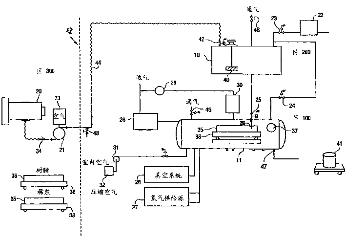
图2以方框示意图形式表示稀浆/树脂浇注系统的主要部件;Figure 2 shows the main components of the slurry/resin pouring system in the form of a schematic block diagram;
图3是用于稀浆/树脂浇注系统的控制构造的方框图;Figure 3 is a block diagram of a control configuration for a slurry/resin casting system;
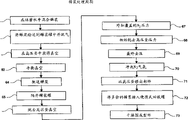
图4是描述稀浆处理周期的流程图;Figure 4 is a flow chart describing the slurry processing cycle;
图5是表示树脂处理周期的流程图;以及Figure 5 is a flow chart representing a resin treatment cycle; and
图6是表示用于稀浆/树脂浇注系统的清洗周期。Figure 6 is a diagram showing the cleaning cycle for the slurry/resin casting system.
发明详述Detailed description of the invention
图1表示稀浆/树脂浇注系统8,包括高压釜11和罐10,周围有平台13和上下扶梯12。图1中还示出阀装置14,该装置提供一个罐10、高压釜11和下面讨论的其它设备之间的阀连接用的集中位置。如图1中所示,罐10和高压釜11结合为一个相当紧凑而可以接近的设施。Figure 1 shows a slurry/resin pouring system 8 comprising an
工作平台11和扶梯12使得可以接近罐10。该构造应当符合所有可以利用的OSHA和地区建筑法规规格。A working
图2中更详细地示出稀浆/树脂浇注系统8。图2中,罐2连接在高压釜11上并通过隔板输送泵21连接在球磨机20上。球磨机20置于罐10和高压釜11的远处,在壁的另一侧。The slurry/resin casting system 8 is shown in more detail in FIG. 2 . In FIG. 2 , the tank 2 is connected to the
一个真空系统(未示出)通过阀22、23连接在罐10上并通过辅助阀24连接在高压釜11上。罐10和高压釜11之间的连接通过节流阀形成。高压釜11也通过一组阀26连接在真空系统上并通过一组阀27连接在一个氮气源(未示出)上。高压釜11通过一组阀28排气,阀28与氧传感器29平行,氧传感器与一组阀70串联连接。最后,室内空气和压缩空气通过泵31供给到高压釜11,而压缩空气还通过一组阀32供给到泵31。A vacuum system (not shown) is connected to the
当高压釜容器的压力高于环境压力时,提供联锁来防止运行阀不适当地开通。例如高压釜11内的过压状态将导致系统失效而关闭氮气供给线。An interlock is provided to prevent inappropriate opening of the run valve when the pressure of the autoclave vessel is above ambient pressure. For example an overpressure condition within the
高压釜11内高于编制程序的阈值限度的氧的存在将导致系统失效而阻止能量输往台板加热元件。氧传感器具有0~25%的范围,传感器最好能容忍高于25%的氧偏差而不会损伤传感器。The presence of oxygen in the
相地于加热台板的超过温度的状态将导致系统失效并导致能量从台板加热元件除去。Conditions of excess temperature relative to the heated platen will cause the system to fail and cause energy to be removed from the platen heating element.
一种高压釜门打开机构的联锁防止人进入高压釜内部,直到内部压力在环境压力的小的容差范围内的高压釜内的氧含量已恢复到超过19.5%的水平(正常氧含量为20.9%)。高压釜11能够通过阀45与大气通气,而罐10能够通过阀46与大气通气。An interlock of an autoclave door opening mechanism prevents persons from entering the interior of the autoclave until the oxygen content in the autoclave has returned to a level exceeding 19.5% (normal oxygen content is 20.9%). Autoclave 11 can be vented to atmosphere through
所有上述联锁都是硬线连接而不需要利用软件控制系统来实施联锁。All of the above interlocks are hardwired and do not require the use of a software control system to implement the interlocks.
球磨机20用来混合SiC稀浆。在该工艺中不需要减小粒径。A ball mill 20 is used to mix the SiC slurry. No particle size reduction is required in this process.
滚动车38上安置一个Naigene部件容器35、36。车38用一手推车(未示出)移动。预成型件将安置在部件容器35、36中而整个包装件滑离手推车而进入高压釜11。输送管39将稀浆供给源连接到例如部件容器35上。A Naigene (R)
带有氯丁橡胶隔板的不锈钢隔板泵21提供压力而将稀浆从球磨机20泵入罐10。球磨机20通过阀34连接到泵21上,而一组阀33向泵21供给大气空气。软管44一端连接排放阀43而在罐的一端连接节流阀42。A stainless
可以有两种放气方法。第一,可以在从球磨机20输送稀浆之前抽空罐10。当稀浆进入罐10时,它将被引到罐壁而促进放气。或者是,整个稀浆的装料(约20加仑)可以在正常状态下输送而大量脱气。There can be two deflation methods. First, the
一台带有四个内罐挡板(未示出)的四叶片桨轮混合器40用于搅拌罐10内的稀浆。A four blade
在真空条件(28”Hg)下,将通过自动操作的节流阀25把稀浆计量通入高压釜11。操作人员能通过视窗37而判断高压釜11中的稀浆水平,并且当输送了足够的稀浆时手动关闭节流阀25。Under vacuum conditions (28" Hg), the slurry will be metered into the
氮气源(未示出)用来向高压釜11外加压力。对压力水平编制程序,并通过图3中示出的系统的可编程序逻辑控制器(PLC)50进行控制。在示范的实施例中,最大压力为125psi。A nitrogen source (not shown) was used to apply pressure to the
该压力逐渐减到周围环境压力。一个鼓风机(未示出)通过高压釜提供足够的气流,以便在允许门(未示出)打开之前保证安全的氧水平。如前所述,提供一个带联锁的笛阀,以便当高压釜11仍然在压力下时防止过早开门。The pressure is gradually reduced to the ambient pressure. A blower (not shown) provides sufficient air flow through the autoclave to maintain safe oxygen levels before allowing the door (not shown) to open. As previously mentioned, a flute valve with interlock is provided to prevent premature door opening while the
在高压釜11打开后排泄孔47可以从部件容器35除去过量的稀浆。过量的稀浆例如可以排入便携式回收罐41中。
如图6中所示,系统的清洗可以用三个独立的过程96、97和98来容易地完成。球磨机20和隔板泵21利用通过一排泄阀处置到一容器中的冲洗水而在过程95中清洗。所有其它软管和输送管线快速地断开,以便如过程96和97所示地进行远清洗。As shown in FIG. 6 , cleaning of the system can be easily accomplished in three separate processes 96 , 97 and 98 . The ball mill 20 and
球磨机20具有90加仑的总球磨容量和60加仑的稀浆容量。罐10最好用不锈钢制成并具有75加仑的容量。高压釜11最好用碳素钢制成并具有48”×48”×30”的容量。回收罐41最好具有25加仑的容量并用不锈钢制成。Ball mill 20 has a total ball milling capacity of 90 gallons and a slurry capacity of 60 gallons.
使用带有可置换软管的凸轮和槽配件来将稀浆从隔板泵21输送到稀浆罐10。所有与稀浆接触的阀都是节流阀,以减少堵塞或卡住的可能性。所有其它采用的阀是弹子阀、球形阀、隔板阀或电磁阀。A cam and groove fitting with replaceable hoses is used to transfer the slurry from the
树脂混合是在远处的树脂处理实验室中完成的。树脂从便携式罐(未示出)配送入部件容器36中。高压釜11的处理最好包括下列设定或参数:真空为28”Hg真空容量;压力为125psi N2压力容量;热量为2小时加热至150℃,在150℃保持30分钟,断掉并在压力下冷却;通过向大气通气并打开高压釜11和移出部件容器36而完成移出步骤。Resin mixing is done in a remote resin processing laboratory. Resin is dispensed into
将稀浆从球磨机20输送到罐10包括下列步骤:手工称重稀浆原料;将称重的原料输送到球磨机20;在球磨机20中搅动稀浆混合物;通过空气作动力的隔板输送泵21将物料从球磨机20输送到罐10。Transporting the slurry from the ball mill 20 to the
在靠近泵21的控制台(未示出)和罐10上的控制台(未示出)上可接触到起动泵21和停止泵21的控制器。The controls for starting and stopping the
罐10利用联锁来防止过分充满和通过阀46排气。该系统能够在输送操作期间抽真空和随后转到输送操作。保持稀浆的罐混合器39可以与输送操作或脱气周期无关地开始和停止。
如图4中所示的稀浆处理周期包括步骤60~73。步骤60涉及在球磨机20中混合该稀浆。步骤61涉及将稀浆输到保持罐10并对稀浆脱气。步骤62涉及将高压釜11的压力从环境状态带到编制程序的真空水平。步骤64涉及在高压釜11和稀浆保持罐10中平衡真空。步骤64涉及在操作人员指令下打开稀浆保持罐和高压釜11之间的阀25。步骤65涉及从高压釜11隔开稀浆保持罐10。步骤66涉及释放高压釜真空(抽吸大气压力)。步骤67涉及外加覆盖的氮气压力。步骤68涉及高压釜的初始放气。步骤69涉及高压釜11的最终卸压。步骤70涉及冲洗氮气氛并确证恢复正常的氧水平。步骤71涉及打开高压釜门和从高压釜移出部件。步骤72涉及在高压釜外面将过量稀浆排入便携式回收罐41。最后,步骤73涉及在高压釜外面使预成型部件空气风干。The slurry processing cycle as shown in FIG. 4 includes steps 60-73. Step 60 involves mixing the slurry in the ball mill 20 . Step 61 involves transferring the slurry to holding
如图5中所示,树脂处理周期包括步骤80~91。步骤80涉及在混合室内制备树脂,并将树脂转移到一个或多个混合罐内。步骤81涉及将罐运到高压釜11。步骤82涉及在高压釜外面对混合罐增压而将树脂从罐移入部件容器36。步骤83涉及打开高压釜门,使充满树脂的部件容器36滚入高压釜,并关上高压釜门。步骤84涉及,如果需要真空周期,就地高压釜外加真空并运转编制程序的真空周期(逐渐到真空并停止)。如果不需要真空,过程就跳到步骤86。步骤85涉及释放高压釜真空(抽吸到大气压力)。步骤86涉及外加氮气压力。在步骤87中,如果高压釜的氧含量低于燃烧阈值,那么就起动可编程序的温度周期。步骤88涉及通过压力控制器内的编制程序而外加压力周期,并预先形成高压釜压力的初始放气。步骤89涉及将最终的卸压预先形成到接近大气压力。步骤90涉及从加热元件消去电能,冲洗氮气氛,并确证正常氧气水平的恢复。最后,步骤91涉及打开高压釜11并从高压釜11中移出部件。As shown in Figure 5, the resin treatment cycle includes steps 80-91. Step 80 involves preparing the resin within the mixing chamber and transferring the resin to one or more mixing tanks. Step 81 involves transporting the tank to the
图3中示出的控制系统包括三个控制区:高压釜区100、稀浆保持区200和稀浆制备区300。PLC 50用于操纵这些控制区内和相互之间的联锁,执行顺序的处理步骤,监控硬线连接的安全联锁的状态,使得能够手动控制系统元件,并收集处理数据。最好是,该系统使用一个GE 30/90 PLC来实现上述功能。The control system shown in FIG. 3 includes three control zones: an autoclave zone 100 , a slurry holding zone 200 and a slurry preparation zone 300 . The PLC 50 is used to manipulate the interlocks within and between these control areas, execute sequential process steps, monitor the status of hardwired safety interlocks, enable manual control of system elements, and collect process data. Preferably, the system uses a
该系统利用一个图形操作负接口终端(OIT)55来控制和观察控制元件和设定点的状态并处理每个处理区内的控制环路的变数。OIT 55用于起动用于稀浆保持区的真空压力周期与高压釜中的真空、压力和加热周期。OIT 55提供所有硬线连接的安全联锁的图形显示来检查与每个联锁相关的传感器状态。The system utilizes a Graphical Operator Interface Terminal (OIT) 55 to control and observe the status of control elements and setpoints and handle control loop variables within each process zone. The OIT 55 is used to start the vacuum pressure cycle for the slurry holding zone and the vacuum, pressure and heat cycle in the autoclave. The OIT 55 provides a graphical display of all hardwired safety interlocks to check the status of the sensors associated with each interlock.
OIT 55也提供用于误差控制或控制处理环路外的警报信息。单个的单独环路处理控制器51、52、53、54用于调节高压釜和稀浆保持区之间和之内的处理状态。The OIT 55 also provides alarm information for error control or outside the control processing loop. A single individual loop process controller 51, 52, 53, 54 is used to regulate process conditions between and within the autoclave and slurry holding zone.
提供一个视频图形记录仪来记录处理周期期间的真实处理变数。视频图形记录仪56设有一个Ethernet(以太网)接口和PCMCIA存储卡,以便于将处理数据从该记录器输往一台PC(未示出)或包括用于归档或进一步分析的网络(未示出)。处理条件用的设定点参数将通过OIT 55进入。输送到PLC 50,并转送到单个的过程控制器51~54。A video graphic recorder is provided to record real process variables during the process cycle. The videographic recorder 56 is provided with an Ethernet (Ethernet) interface and PCMCIA memory card, so that processing data can be exported from this recorder to a PC (not shown) or include the network (not shown) for archiving or further analysis. Shows). Setpoint parameters for processing conditions will be entered through OIT 55. sent to PLC 50, and forwarded to individual process controllers 51-54.
在PLC 50和单个过程控制器51~54之间设置一个交流接口,能够支持将处理周期参数输送到过程控制器51~54,并将过程状态和误差状态从过程控制器51~54输送到PLC 50。PLC 50和过程控制器51~54之间的交流接口最好是Modbus。An exchange interface is provided between the PLC 50 and the individual process controllers 51-54, which can support the transmission of process cycle parameters to the process controllers 51-54, and the process status and error status from the process controllers 51-54 to the PLC 50. The communication interface between the PLC 50 and the process controllers 51-54 is preferably Modbus.
高压釜区100包括软件编程的联锁来管理真空、正压、加热、通气和OSHA安全氧水平的恢复之间的过程过渡。高压釜区100也包括硬线连接的安全联锁以减轻下述失误条件的冲击:过压;在能够支持燃烧的氧水平的存在下外加电加热;用于加热的高压釜台板的超过温度的状态;在非接近零的计量压力的高压釜压力的存在下试图打开门;在不存在安全的氧水平(>19.5%O2)的情况下试图打开高压釜门;当高压釜压力大于大气压力时试图打开稀浆保持罐和高压釜之间的阀;以及当高压釜压力大于大气压力时试图打开高压釜的大体积通气和鼓风机阀。The autoclave zone 100 includes software programmed interlocks to manage process transitions between vacuum, positive pressure, heat, aeration, and restoration of OSHA safe oxygen levels. The autoclave zone 100 also includes hardwired safety interlocks to mitigate the impact of the following fault conditions: overpressure; external electrical heating in the presence of oxygen levels capable of supporting combustion; overtemperature of the autoclave platen for heating. status; attempt to open door in the presence of autoclave pressure other than near zero gauge pressure; attempt to open autoclave door in the absence of safe oxygen levels (>19.5% O2 ); when autoclave pressure is greater than atmospheric pressure attempts to open the valves between the slurry holding tank and the autoclave; and attempts to open the bulk vent and blower valves of the autoclave when the autoclave pressure is greater than atmospheric pressure.
高压釜11包括分散的控制台58,当通过视窗观察高压釜11时操作人员可以接近该台。该操作人员能够从控制台接通或断开高压釜照明,平衡高压釜11和稀浆保持罐10中的真空压力,确证两个区处在相等的压力,并在高速率和低速率下控制将稀浆释放到高压釜11中。如果一种系统失误条件存在,该控制台将提供一个失误指示灯来提醒操作人员。高压釜区还包括过程控制器来调节真空周期、压力周期和加热周期的倾斜率和停留时间。The
该过程周期包括一个软件编程的联锁,以防止通常含氧的气氛的恢复,直到高压釜11低于一目标温度。该连锁有助于防止一种由于同时存在可燃燃料(未催化的树脂)、氧和点燃源(高温)而产生的可能的燃烧危险。高压釜11包括自动控制的阀以控制进出高压釜的流。这些物料包括真空下的稀浆、高压釜和稀浆保持罐之间的真空平衡、借助于氮的增压、真空、各种压力状态下的通气及正常的气氛互变。The process cycle includes a software programmed interlock to prevent reinstatement of the normally oxygen containing atmosphere until the
设有各控制阀,因此真空变化速率和真空压力能通过一个过程控制器得到数字控制。同样,设有控制阀和各种装置,使得压力变化速率和压力能通过一个过程控制器得到数字控制。独立的过程控制器控制真空和压力。Control valves are provided so the rate of vacuum change and vacuum pressure can be digitally controlled by a process controller. Also, control valves and devices are provided so that the rate of pressure change and pressure can be digitally controlled by a process controller. Independent process controllers control vacuum and pressure.
该系统包括能够在真空方式下完成倾斜和停顿周期与在正计量压力方式下完成增压周期。使用各压力开关来检测真空、环境压力和上述环境压力方式之间的转换,以便制定处理程序和增强安全联锁。The system includes the ability to perform ramp and dwell cycles in vacuum mode and boost cycles in positive gauge pressure mode. Individual pressure switches are used to detect transitions between vacuum, ambient pressure, and the above ambient pressure modes for handling procedures and enhanced safety interlocks.
高压釜支承多到四个的K型热电偶温度传感器。三个温度传感器专用于调节部件处理温度。两个传感器用于测量工具表面温度和部件温度两者的串联控制方案中。另一温度传感器用于一种独立的超过温度联锁。余下的温度传感器可用于总的过程监控。The autoclave supports up to four K-type thermocouple temperature sensors. Three temperature sensors are dedicated to regulating the part process temperature. Two sensors are used in a series control scheme that measures both tool surface temperature and component temperature. Another temperature sensor is used for an independent over-temperature interlock. The remaining temperature sensors can be used for overall process monitoring.
高压釜内的压力利用一个能够感知一14.7psig~150psig的复合范围压力换能器监控。该压力换能器供给一个BRAIN增强的4~20mA信号。该压力换能器包括一个局部压力显示器。高压釜压力可通过OIT55看见。The pressure in the autoclave was monitored using a compound range pressure transducer capable of sensing - 14.7 psig to 150 psig. The pressure transducer supplies a BRAIN enhanced 4-20mA signal. The pressure transducer includes a partial pressure indicator. Autoclave pressure can be seen through OIT55.
如果高压釜气氛对人的暴露是安全的或不足以燃烧,那么氧传感器及相关的警报输出用于显示高压釜内流动氧含量和氧状态。加热控制器的尺寸大到足以支持16KW的加热器最大功率。If the autoclave atmosphere is safe for human exposure or not sufficient for combustion, an oxygen sensor and associated alarm output is used to indicate the oxygen content and status of the oxygen flowing in the autoclave. The heating controller is large enough to support a maximum heater power of 16KW.
稀浆保持区200包括一过程控制器以测定真空变化率和真空压力下的调节。如果罐压力小于或等于大气压力,那么就不提供以稀浆保持罐为基础的特定联锁来防止或限制稀浆从稀浆制备区转移到稀浆保持罐。如果稀浆保持罐的压力大于大气压力,那么就提供一个硬线连接的联锁来防止稀浆保持罐和稀浆制备区之间的阀打开。The slurry holding zone 200 includes a process controller to measure the vacuum ramp rate and adjustments under vacuum pressure. If the tank pressure is less than or equal to atmospheric pressure, no specific slurry holding tank based interlock is provided to prevent or limit the transfer of slurry from the slurry preparation area to the slurry holding tank. If the slurry holding tank is at a pressure greater than atmospheric pressure, a hardwired interlock is provided to prevent opening of the valve between the slurry holding tank and the slurry preparation area.
稀浆保持罐装有四个限止开关以检测罐内的填充水平。这些开关是低-低、低、高和高-高水平警报。正常的最大填充水平是高警报。水平开关的状态显示在OIT 55上。The slurry holding tank is equipped with four limit switches to detect the fill level in the tank. These switches are low-low, low-high, and high-high level alarms. The normal maximum fill level is a high alarm. The state of the level switch is displayed on the OIT 55.
稀浆混合器40用OIT 55驱动。混合器40装备一个传感器来确证混合器轴正在转动。该混合器用一个带齿轮箱的三相AC感应电动机驱动。
罐10内的压力用一个能够感知一14.7psig~150psig的复合范围压力换能器来监控。该压力换能器供给一个BRAIN增强的4~20mA的信号。该压力换能器包括一个局部压力显示器。稀浆保持罐压力可以通过OIT 55看见。The pressure within
稀浆制备区300包括输送控制台58以便于将树脂从球磨机20输送到罐10。该操作台包括一个指示“准备输送”的灯。该灯暗示罐10未充满,过程中没有稀浆分配(平衡阀关闭和稀浆节流阀关闭),而罐10没有处在高于环境的压力。按钮起动和停止输送过程。The slurry preparation area 300 includes a transfer console 58 to facilitate the transfer of resin from the ball mill 20 to the
泵抽速率是通过供给的空气压力而控制的。提供一个手动调节器来改变该空气压力。“输送”灯指示空气正供给到隔板输送泵21而稀浆罐节流阀是打开的。电磁阀33用于起动和停止气流通向隔板泵21。一个压力开关使电磁阀33的操作有效。The pumping rate is controlled by the air supply pressure. A manual regulator is provided to vary this air pressure. The "DELIVERY" light indicates that air is being supplied to the
当稀浆保持罐10中的水平到达高或高-高限度时,泵21自动停止。稀浆过程中的驱动器的失效导致“输送失效”。在稀浆制备控制台上设置一个指示灯。OIT 55地所有反馈装置显示信号。When the level in the
在罐10上设置一个同样的输送控制台59’,以便当操作人员靠近用于将稀浆制备区连接到罐10上的弯曲软管44快速断开阀43时起动/停止输送。A similar transfer control console 59'
虽然本发明是联系目前认为是最实用的优选实施例来描述的,但可以理解,本发明不限于所公开的实施例,相反,本发明预定包括落在附属的权利要求书的精神和范围内的各种修改和等效的配置。While the invention has been described in connection with what are presently considered to be the most practically preferred embodiments, it is to be understood that the invention is not limited to the disclosed embodiments, but rather, the invention is intended to be encompassed within the spirit and scope of the appended claims. Various modifications and equivalent configurations of .
部分清单partial list
稀浆/树脂浇注系统 8Slurry/Resin Casting System 8
罐 10
高压釜 11
上下扶梯 12Up and down the escalator 12
平台 13Platform 13
阀装置 14Valve device 14
球磨机 20Ball mill 20
隔板输送泵 21
阀 22、23、24、26、27、28、30、32、33、34、35、46
节流阀 25、42
氧传感器 29
泵 31
Naigene部件容器 35、36 Naigene®
视窗 37
滚动车 38
输送管 39
四叶片桨轮混合器 40Four blade
便携式回收罐 41
断开阀 43Disconnect
软管 44
排泄口 47
系统可编程逻辑控制器(PLC) 50System Programmable Logic Controller (PLC) 50
单一环路过程控制器 51、52、53、54Single loop process controller 51, 52, 53, 54
操作接口终端 55Operation interface terminal 55
视频图形记录仪 56Video Graphics Recorder 56
硬线连接的安全联锁 57Hardwired Safety Interlocks 57
分散的控制台 58Decentralized Console 58
输送控制台 59、59’Conveyor console 59, 59’
Claims (10)
Applications Claiming Priority (2)
| Application Number | Priority Date | Filing Date | Title |
|---|---|---|---|
| US10/648355 | 2003-08-27 | ||
| US10/648,355 US6830079B1 (en) | 2003-08-27 | 2003-08-27 | Integrated apparatus and method for filling porous composite preforms |
Publications (1)
| Publication Number | Publication Date |
|---|---|
| CN1623751A true CN1623751A (en) | 2005-06-08 |
Family
ID=33490945
Family Applications (1)
| Application Number | Title | Priority Date | Filing Date |
|---|---|---|---|
| CN200410068258.1A Pending CN1623751A (en) | 2003-08-27 | 2004-08-27 | Integrated apparatus and method for filling porous composite preforms |
Country Status (4)
| Country | Link |
|---|---|
| US (1) | US6830079B1 (en) |
| EP (1) | EP1510328A3 (en) |
| JP (1) | JP2005096436A (en) |
| CN (1) | CN1623751A (en) |
Families Citing this family (21)
| Publication number | Priority date | Publication date | Assignee | Title |
|---|---|---|---|---|
| US8438909B2 (en) * | 2006-12-22 | 2013-05-14 | The Boeing Company | Device and method for detecting an air leak in a tool |
| US7849729B2 (en) | 2006-12-22 | 2010-12-14 | The Boeing Company | Leak detection in vacuum bags |
| US9770871B2 (en) | 2007-05-22 | 2017-09-26 | The Boeing Company | Method and apparatus for layup placement |
| US8568551B2 (en) | 2007-05-22 | 2013-10-29 | The Boeing Company | Pre-patterned layup kit and method of manufacture |
| US8936695B2 (en) | 2007-07-28 | 2015-01-20 | The Boeing Company | Method for forming and applying composite layups having complex geometries |
| US8333864B2 (en) * | 2008-09-30 | 2012-12-18 | The Boeing Company | Compaction of prepreg plies on composite laminate structures |
| US8707766B2 (en) | 2010-04-21 | 2014-04-29 | The Boeing Company | Leak detection in vacuum bags |
| US7662048B2 (en) * | 2007-10-18 | 2010-02-16 | Libby Jason Armas | Golf swing training device |
| US8752293B2 (en) | 2007-12-07 | 2014-06-17 | The Boeing Company | Method of fabricating structures using composite modules and structures made thereby |
| US8916010B2 (en) | 2007-12-07 | 2014-12-23 | The Boeing Company | Composite manufacturing method |
| US10280063B2 (en) * | 2016-02-19 | 2019-05-07 | Alexander G. Innes | Pressurized transfer device |
| US10864640B1 (en) * | 2017-12-26 | 2020-12-15 | AGI Engineering, Inc. | Articulating arm programmable tank cleaning nozzle |
| US11413666B1 (en) | 2018-02-13 | 2022-08-16 | AGI Engineering, Inc. | Vertical travel robotic tank cleaning system |
| US11031149B1 (en) | 2018-02-13 | 2021-06-08 | AGI Engineering, Inc. | Nuclear abrasive slurry waste pump with backstop and macerator |
| US10786905B1 (en) | 2018-04-16 | 2020-09-29 | AGI Engineering, Inc. | Tank excavator |
| US11577287B1 (en) | 2018-04-16 | 2023-02-14 | AGI Engineering, Inc. | Large riser extended reach sluicer and tool changer |
| HUE068879T2 (en) | 2018-06-11 | 2025-01-28 | Alex G Innes | Programmable railcar tank cleaning system |
| US11267024B2 (en) | 2018-06-11 | 2022-03-08 | AGI Engineering, Inc. | Programmable tank cleaning nozzle |
| CN109719972B (en) * | 2019-01-26 | 2023-08-18 | 浙江理工大学 | Resin injection device for preparing composite pipe fitting and control method |
| US11571723B1 (en) | 2019-03-29 | 2023-02-07 | AGI Engineering, Inc. | Mechanical dry waste excavating end effector |
| CN112247098B (en) * | 2020-09-21 | 2022-05-24 | 蚌埠隆华压铸机有限公司 | Anti-explosion hand-clamping-preventing device of die casting machine |
Family Cites Families (18)
| Publication number | Priority date | Publication date | Assignee | Title |
|---|---|---|---|---|
| GB286305A (en) * | 1927-03-03 | 1929-05-09 | Manuf De Machines Auxiliaires | Method and means for impregnating any articles with varnishes of synthetic resins |
| JPS608222B2 (en) * | 1976-06-01 | 1985-03-01 | 旭硝子株式会社 | Resin in-die extension molding method |
| EP0000755B1 (en) | 1977-08-05 | 1981-12-16 | Walter Schwarz | Method and apparatus for making a shaped body from reinforced plastic |
| US4609563A (en) * | 1985-02-28 | 1986-09-02 | Engelhard Corporation | Metered charge system for catalytic coating of a substrate |
| US5111871B1 (en) * | 1989-03-17 | 1993-12-28 | J. Cook Arnold | Method of vacuum casting |
| JPH0729304B2 (en) * | 1992-02-26 | 1995-04-05 | 川崎重工業株式会社 | Composite material molding method and molding apparatus |
| US5299619A (en) * | 1992-12-30 | 1994-04-05 | Hitchiner Manufacturing Co., Inc. | Method and apparatus for making intermetallic castings |
| US5340512A (en) * | 1993-01-29 | 1994-08-23 | Thomas & Betts Corporation | Polymer concrete electrical insulator and method and apparatus for making |
| US5489408A (en) * | 1993-03-08 | 1996-02-06 | Agency Of Industrial Science & Technology | Method for producing ceramics reinforced with three-dimensional fibers |
| JPH07169658A (en) * | 1993-07-02 | 1995-07-04 | Electro Scient Ind Inc | Device to attach terminating paste to electronic device |
| DE69506447T2 (en) * | 1995-01-27 | 1999-07-01 | Sikorsky Aircraft Corp., Stratford, Conn. | METHOD FOR PRODUCING COMPOSITE MATERIALS PROVIDED WITH A HONEYCOMB-CORE CORE |
| US6148899A (en) * | 1998-01-29 | 2000-11-21 | Metal Matrix Cast Composites, Inc. | Methods of high throughput pressure infiltration casting |
| US6099906A (en) * | 1998-06-22 | 2000-08-08 | Mcdonnell Douglas Corporation | Immersion process for impregnation of resin into preforms |
| JP2002060514A (en) * | 2000-08-17 | 2002-02-26 | Mitsubishi Gas Chem Co Inc | Manufacturing method of prepreg |
| JP2002086439A (en) * | 2000-09-19 | 2002-03-26 | Matsushita Electric Works Ltd | Controlling method of thickness of fiber reinforced cement plate |
| JP4839523B2 (en) * | 2001-04-17 | 2011-12-21 | 東レ株式会社 | Manufacturing method of fiber reinforced resin |
| JP4590803B2 (en) * | 2001-08-20 | 2010-12-01 | 東レ株式会社 | RTM molding method |
| DE10239325B4 (en) * | 2002-08-27 | 2011-06-01 | Mt Aerospace Ag | Device, tool arrangement and method for the production of components made of fiber composite materials by means of temperature and pressure controlled injection technique |
-
2003
- 2003-08-27 US US10/648,355 patent/US6830079B1/en not_active Expired - Fee Related
-
2004
- 2004-08-26 JP JP2004246126A patent/JP2005096436A/en active Pending
- 2004-08-26 EP EP04255147A patent/EP1510328A3/en not_active Withdrawn
- 2004-08-27 CN CN200410068258.1A patent/CN1623751A/en active Pending
Also Published As
| Publication number | Publication date |
|---|---|
| EP1510328A2 (en) | 2005-03-02 |
| JP2005096436A (en) | 2005-04-14 |
| US6830079B1 (en) | 2004-12-14 |
| EP1510328A3 (en) | 2011-05-11 |
Similar Documents
| Publication | Publication Date | Title |
|---|---|---|
| CN1623751A (en) | Integrated apparatus and method for filling porous composite preforms | |
| US5529212A (en) | Method of and apparatus for transporting and conditioning casting materials and for charging casting machines with them | |
| CN1942365A (en) | Auto-switching system for switch-over of gas storage and dispensing vessels in a multi-vessel array | |
| CN110976871B (en) | Powder recovery circulation system and control method of selective laser sintering equipment | |
| CN110985235B (en) | Continuous casting system and process for solid rocket engine shell | |
| CN112126910A (en) | Control method in diamond growth system based on PLC | |
| US20160136663A1 (en) | Method for lining a pipe with a cement mortar | |
| CN113390728A (en) | Full-automatic robot external measurement method hydrostatic test system and method | |
| CN1749346A (en) | Automatic continuous producing device system and method for seal glue | |
| CN114433413A (en) | Honeycomb carrier ration is given thick liquid coating equipment | |
| CN1805811A (en) | Molten metal feed system, container, and vehicle | |
| CN117942810A (en) | Apparatus and method for producing electrolyte solutions | |
| CN223433016U (en) | Powder medicine unloading device | |
| CN209974964U (en) | Continuous feeding mechanism for metal silicon smelting furnace | |
| CN211886799U (en) | An intelligent heating and cooling device for chemical manufacturing equipment | |
| CN204016876U (en) | A kind of dropping pill formulation process units | |
| CN117245777A (en) | Inorganic artificial stone plate production system and production process thereof | |
| CN110004490A (en) | Continuous feeding mechanism for silicon metal smelting furnace and using method thereof | |
| CN2594642Y (en) | Movable full-automatic chemical cleaning equipment | |
| CN1853829A (en) | Container, method of supplying aluminum alloy and system for producing aluminum alloy | |
| CN113512636A (en) | Vertical vacuum heat treatment furnace | |
| CN220026709U (en) | Automatic stirring, mixing and adding device for water treatment medium | |
| CN207308158U (en) | Environment-friendly high-efficiency does not choose oil product full-automatic spray oil machine | |
| CN219855476U (en) | A cooling and conveying production line for pellet materials | |
| CN118927492A (en) | A static mixing casting system for transformers |
Legal Events
| Date | Code | Title | Description |
|---|---|---|---|
| C06 | Publication | ||
| PB01 | Publication | ||
| C10 | Entry into substantive examination | ||
| SE01 | Entry into force of request for substantive examination | ||
| C12 | Rejection of a patent application after its publication | ||
| RJ01 | Rejection of invention patent application after publication |
Application publication date: 20050608 |