CN1676902A - Controlled pressure fuel nozzle system - Google Patents
Controlled pressure fuel nozzle system Download PDFInfo
- Publication number
- CN1676902A CN1676902A CN 200510054199 CN200510054199A CN1676902A CN 1676902 A CN1676902 A CN 1676902A CN 200510054199 CN200510054199 CN 200510054199 CN 200510054199 A CN200510054199 A CN 200510054199A CN 1676902 A CN1676902 A CN 1676902A
- Authority
- CN
- China
- Prior art keywords
- fuel
- nozzle
- fuel injection
- injection pipe
- injector
- Prior art date
- Legal status (The legal status is an assumption and is not a legal conclusion. Google has not performed a legal analysis and makes no representation as to the accuracy of the status listed.)
- Granted
Links
Images


Classifications
-
- F—MECHANICAL ENGINEERING; LIGHTING; HEATING; WEAPONS; BLASTING
- F23—COMBUSTION APPARATUS; COMBUSTION PROCESSES
- F23R—GENERATING COMBUSTION PRODUCTS OF HIGH PRESSURE OR HIGH VELOCITY, e.g. GAS-TURBINE COMBUSTION CHAMBERS
- F23R3/00—Continuous combustion chambers using liquid or gaseous fuel
- F23R3/28—Continuous combustion chambers using liquid or gaseous fuel characterised by the fuel supply
- F23R3/34—Feeding into different combustion zones
- F23R3/343—Pilot flames, i.e. fuel nozzles or injectors using only a very small proportion of the total fuel to insure continuous combustion
Landscapes
- Engineering & Computer Science (AREA)
- Chemical & Material Sciences (AREA)
- Combustion & Propulsion (AREA)
- Mechanical Engineering (AREA)
- General Engineering & Computer Science (AREA)
- Pressure-Spray And Ultrasonic-Wave- Spray Burners (AREA)
- Fuel-Injection Apparatus (AREA)
Abstract
多级燃气轮机燃料供给燃料系统的燃料喷射器(10)至少包括具有第一和第二燃料喷射点(413和414)的第一和第二级燃料喷射管路(411和412),至少第一和第二燃料喷嘴阀(415和416)分别在不同的第一和第二打开压力(419和420)的条件下运行打开,这些燃料喷嘴阀与第一和第二级燃料喷射管路(411和412)分别可控地相连。单根燃料供给岐管(409)与所有的燃料喷嘴阀(415和416)相连。单个燃料信号岐管(16)与所有的第一和第二燃料喷嘴阀(415和416)可控地相连。燃料喷射器(10)包括容纳有燃料喷嘴阀(415和416)的阀套(43)。
A fuel injector (10) of a multi-stage gas turbine fuel supply fuel system includes at least first and second-stage fuel injection lines (411 and 412) having first and second fuel injection points (413 and 414), at least the first and second fuel nozzle valves (415 and 416), which are connected to first and second stage fuel injection lines (411 and 412) are controllably connected respectively. A single fuel supply manifold (409) is connected to all fuel nozzle valves (415 and 416). A single fuel signal manifold (16) is controllably connected to all of the first and second fuel nozzle valves (415 and 416). The fuel injector (10) includes a valve housing (43) that houses fuel nozzle valves (415 and 416).
Description
技术领域technical field
本发明一般涉及燃气轮机燃烧室的燃料喷射器,尤其是涉及用于分级的燃料供给系统中的燃料喷射器。This invention relates generally to fuel injectors for gas turbine combustors, and more particularly to fuel injectors for use in staged fuel delivery systems.
背景技术Background technique
为了降低排放量,燃气轮机采用稀薄燃烧的燃烧器,此燃烧器需要在一定范围的运行条件下打开和关闭独立的燃料管路,此运行条件包括发动机功率水平和环境因素。这通常称为燃料分级并且它需要保持发动机的局部空燃比在一较窄的范围内,此范围的上限由NOx排放确定,下限由熄火边界确定。To reduce emissions, gas turbines employ lean-burn combustors that require individual fuel lines to be opened and closed over a range of operating conditions, including engine power levels and environmental factors. This is commonly known as fuel staging and it entails maintaining the engine's local air-fuel ratio within a narrow range, the upper limit of which is determined by NOx emissions and the lower limit is determined by the flameout boundary.
现有的发动机采用了多根燃料供给岐管的多个独立控制的集中分级阀(centralized staging valves),此燃料供给岐管输送燃料到燃料喷嘴中。每级使用一根燃料供给岐管,因此,每个燃料喷嘴具有多个燃料供给接口,每级采用了一个接口。为了防止结焦,燃料必须从未分级的岐管中排出或者在此岐管中进行持续的循环。这种多岐管的燃料系统是复杂的并且需要多种形状和尺寸的环状的或者弯曲的燃料供给管,以供给燃料到不同级的燃料喷嘴中。理想的是采用一种燃料系统,它具有单根燃料岐管和包含不同级的燃料喷嘴的燃料喷射器。Existing engines employ multiple independently controlled centralized staging valves for multiple fuel supply manifolds that deliver fuel to the fuel nozzles. One fuel supply manifold is used per stage, so each fuel nozzle has multiple fuel supply ports, one port per stage. To prevent coking, the fuel must either be drained from the unstaged manifold or circulate continuously through this manifold. Such multi-manifold fuel systems are complex and require annular or curved fuel supply tubes of various shapes and sizes to supply fuel to the different stages of fuel nozzles. It would be desirable to have a fuel system having a single fuel manifold and fuel injectors comprising different stages of fuel nozzles.
具有多个集中分级阀的燃料系统是昂贵的,并且发动机设计者总是致力于设计一种具有更好的操作响应性和更可靠的燃料系统。集中分级燃料系统在加速阶段速度降低,这是因为在此系统中,在管路中流入燃料之前未分级的燃料岐管必须被加压并且对空体积进行填充。非常理想的是使速度的降低减少。Fuel systems with multiple centralized staging valves are expensive, and engine designers are always striving to design a fuel system with better operational responsiveness and more reliability. Centrally staged fuel systems slow down during the acceleration phase because in this system the unstaged fuel manifold must be pressurized and the empty volume filled before the fuel flows in the lines. It is highly desirable to reduce the reduction in speed.
例如燃气轮机中的燃料喷射器将来自岐管中加压的燃料导入到一个或者多个的燃烧室中。在燃烧之前燃料喷射器也准备将燃料与空气相混合。每个喷射器通常具有与岐管相连的入口装置、与此装置一端相连的管状延伸部分或者杆,以及一个或者多个与杆的另一端相连的喷射喷嘴用于将喷射燃料导入到燃烧室中。燃料管或通道(例如,软管,导管,或者圆筒状通道)延伸穿过杆,从而将燃料从入口装置中供给到喷嘴中。提供合适的阀和/或分流器以引导和控制通过喷嘴的燃料流动。燃料喷射器通常设置在一均匀间隔开的环形装置中,从而能以均匀的方式分配(喷射)燃料到燃烧室中。For example, fuel injectors in gas turbines direct pressurized fuel from a manifold into one or more combustion chambers. The fuel injectors also prepare the fuel to mix with air prior to combustion. Each injector typically has an inlet assembly connected to the manifold, a tubular extension or stem attached to one end of the assembly, and one or more injection nozzles attached to the other end of the stem for introducing injected fuel into the combustion chamber . A fuel tube or passage (eg, a hose, conduit, or cylindrical passage) extends through the rod to feed fuel from the inlet device into the nozzle. Suitable valves and/or flow dividers are provided to direct and control the flow of fuel through the nozzles. The fuel injectors are usually arranged in an evenly spaced annular arrangement to distribute (inject) fuel into the combustion chamber in a uniform manner.
发明内容Contents of the invention
多级燃气轮机燃料供给系统的燃料喷射器包括至少第一和第二级燃料喷射管路。每个第一和第二级燃料喷射管路分别具有第一和第二燃料喷射点和至少第一和第二燃料喷嘴阀,这些燃料喷嘴阀与第一和第二级燃料喷射管路分别可控地地相连。第一和第二燃料喷嘴阀分别在不同的第一和第二打开压力的条件下运行打开。第一和第二燃料喷嘴阀设置在喷射器的阀套内,此喷射器包括以燃料供给关系与第一和第二喷嘴阀相连的单个燃料供给连接器,以及以压力供给关系与第一和第二燃料喷嘴阀相连的单个燃料信号连接器。A fuel injector of a multi-stage gas turbine fuel supply system includes at least first and second stage fuel injection lines. Each of the first and second stage fuel injection lines has first and second fuel injection points, respectively, and at least first and second fuel nozzle valves, which are connectable to the first and second stage fuel injection lines, respectively. Connected to ground. The first and second fuel nozzle valves operate open at different first and second opening pressures, respectively. First and second fuel nozzle valves are disposed within a valve housing of an injector that includes a single fuel supply connector connected in fuel supply relationship to the first and second nozzle valves, and in pressure supply relationship to the first and second fuel nozzle valves. Single fuel signal connector to the second fuel nozzle valve.
在燃料喷射器的一个实施例中,第一级燃料喷射器管路的第一燃料喷射点为燃料喷射器的引燃喷嘴的燃料喷射器顶端中的顶部喷孔。第二级燃料喷射器管路的第二燃料喷射点为燃料喷射器主喷嘴的喷孔。系统还包括在燃料喷射器中具有第三燃料喷射点的第三级燃料喷射管路。第三燃料喷射点也位于燃料喷射器的主喷嘴中。In one embodiment of the fuel injector, the first fuel injection point of the first stage fuel injector line is a top orifice in a fuel injector tip of a pilot nozzle of the fuel injector. The second fuel injection point of the second-stage fuel injector pipeline is the injection hole of the main nozzle of the fuel injector. The system also includes a third stage fuel injection line having a third fuel injection point in the fuel injector. A third fuel injection point is also located in the main nozzle of the fuel injector.
附图说明Description of drawings
图1表示只具有单根燃料供给岐管和单根燃料信号歧管的多级燃气轮机的燃料供给系统的示意图。FIG. 1 shows a schematic diagram of a fuel supply system for a multi-stage gas turbine having only a single fuel supply manifold and a single fuel signal manifold.
图2表示只具有单根燃料供给岐管和单根燃料信号歧管的三级燃气轮机的燃料供给系统的示意图。Figure 2 shows a schematic diagram of a fuel supply system for a three-stage gas turbine having only a single fuel supply manifold and a single fuel signal manifold.
图3表示仅具有单根燃料供给岐管的双重二级燃料喷射器的燃气轮机的燃料供给系统的示意图。FIG. 3 shows a schematic diagram of a fuel supply system for a gas turbine with dual secondary fuel injectors having only a single fuel supply manifold.
图4表示仅具有单根燃料供给岐管的双重三级燃料喷射器的燃气轮机的燃料供给系统的示意图。FIG. 4 shows a schematic diagram of a fuel supply system of a gas turbine with dual three-stage fuel injectors having only a single fuel supply manifold.
图5表示具有本发明示范性实施例的三级燃料喷射器的燃气轮机燃烧室的横截面图。5 shows a cross-sectional view of a gas turbine combustor with a three-stage fuel injector according to an exemplary embodiment of the present invention.
图6表示具有在图5中示出的燃料喷嘴组件的燃料喷射器的放大的横截面图。FIG. 6 shows an enlarged cross-sectional view of a fuel injector having the fuel nozzle assembly shown in FIG. 5 .
图7表示在图6中所示出的燃料喷嘴组件的放大的横截面图。FIG. 7 shows an enlarged cross-sectional view of the fuel nozzle assembly shown in FIG. 6 .
图8表示在图6中所示出的燃料喷射器的透视图。FIG. 8 shows a perspective view of the fuel injector shown in FIG. 6 .
图9表示沿图6中所示的9-9剖开的燃料带的横截面图。Figure 9 shows a cross-sectional view of the fuel ribbon taken along line 9-9 shown in Figure 6 .
图10表示在图5中所示出的用来形成燃料带的平板的顶视图。FIG. 10 shows a top view of the flat panel shown in FIG. 5 used to form the fuel ribbon.
图11表示在图5中所示出的燃料喷射器的燃料管路的示意图。FIG. 11 shows a schematic view of the fuel line of the fuel injector shown in FIG. 5 .
图12表示在图11中所示出的具有燃料管路的燃料带的透视图。FIG. 12 shows a perspective view of the fuel belt with fuel lines shown in FIG. 11 .
图13-16为两个阀的示意图,它示出了所采用的表示仅仅具有单根燃料供应岐管和单根燃料信号歧管的两阀三级燃气轮机燃料供给系统的运行情况。Figures 13-16 are schematic diagrams of two valves showing the operation of a two-valve three-stage gas turbine fuel supply system employed representing only a single fuel supply manifold and a single fuel signal manifold.
具体实施方式Detailed ways
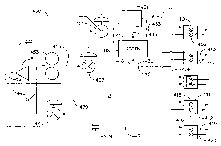
在图1中表示的是多级燃气轮机燃料供给系统8的一个示范性实施例,此燃料供给系统提供燃料到多个燃料喷射器10的每一个中的第一级燃料喷射管路411和第二级燃料喷射管路412中。第一级燃料喷射管路411和第二级燃料喷射管路412中的每一个都具有第一燃料喷射点413和第二燃料喷射点414。第一燃料喷嘴阀415和第二燃料喷嘴阀416分别与第一级燃料喷射管路411和第二级燃料喷射管路412可控地相连。燃料供给管路431包括以燃料供给关系与所有的燃料喷嘴阀415和416相连的单根燃料供给岐管409。第一燃料喷嘴阀415和第二燃料喷嘴阀416分别在不同的第一打开压力419和第二打开压力420的情况下运行打开,正如表示不同的张开压力的不同的箭头长度所示。所有的第一燃料喷嘴阀415和第二燃料喷嘴阀416都与在信号管路433中的单根燃料信号岐管16可控地相连。Shown in FIG. 1 is an exemplary embodiment of a multi-stage gas turbine
图1中表示了燃料喷射器10的一个更特殊的示范性实施例,它包括第一级燃料喷射管路411的第一燃料喷射点413,其中第一燃料喷射点413为在图5和图7所示出的燃料喷射器10的引燃喷嘴58的燃料喷射器顶部57中的顶部喷孔55。第二级燃料喷射管路412的第二燃料喷射点414为图5和图7所示出的燃料喷射器10的主喷嘴59中的喷孔106。如图2所示,系统8还包括具有位于燃料喷射器10中的第三燃料喷射点462的第三级燃料喷射管路460。具有第三打开压力482的第三燃料喷嘴阀480位于第三级燃料喷射管路460中。系统可以具有位于燃料喷射器10中的超过三级的燃料喷射管路460以及超过三级的燃料喷射点462。A more specific exemplary embodiment of a
如图1和图2所示的系统8的示范性实施例还包括压差测量装置418,此装置是用来检测信号管路433中的信号压力417与燃料供给管路431中的燃料供给压力427之间的压差DCPFN。与压差测量装置418成反馈信号关系的燃料控制器421控制着压力调节器422,并且此压力调节器和燃料控制器421可控地相连。燃料控制器421通过控制压力调节器422来控制和调整通过信号管路433的压力,从而控制从信号管路433中的单个燃料信号歧管16中送入燃料喷嘴阀的打开压力。当信号管路433中的压力等于或者超过第一打开压力419时,第一燃料喷嘴阀415打开并且保持打开状态。当信号管路433中的压力等于或者超过第二打开压力420时,第二燃料喷嘴阀416打开并且保持打开状态。这样消除了用于每级中的每个喷射器的多根燃料和信号管路的需要。The exemplary embodiment of the
燃料泵441以燃料供给关系与燃料计量阀437相连,此燃料计量阀437以燃料供给关系与燃料供给岐管409相连。燃料计量阀437与燃料控制器421可控地相连。第一压力输入线路435在压力调节器422和信号管路433之间,并通向压差测量装置418。第二压力输入线路436从燃料计量阀437和燃料供给岐管409之间的燃料供给管路431上的某点处通向压差测量装置418。压差测量装置418通常为压力传感器。此压力传感器可为机械的或电的。
燃料泵441具有一泵出口443,此出口以燃料压力供给关系与压力调节器422相连并且也以燃料供给关系与燃料计量阀437相连。压力调节器422使用在过渡工况或者运行中,它也以压力降的关系通过压力调节器返回线路450与增压泵入口452和增压泵451相连。压力调节器422是三通伺服机构并且当压力调节器422处于关闭或者断开位置时,压力调节器可运转地将压力调节器返回线路450打开。注意的是压力调节器422的关闭或者断开位置并不是说完全关闭了燃料信号岐管16的通路。泵旁通管路439从泵出口443通向泵旁通管路入口440和燃料泵441,并且在其间具有旁通阀445。燃料信号返回线路447从燃料信号歧管16通向燃料信号返回入口442和燃料泵441。返回线路管口449设置在燃料信号返回线路447中。在发动机运行过程中,返回线路管口449允许燃料在信号岐管409中保持流动,并且避免在喷嘴中的结焦,并且降低了通过压力调节器422的压力增益。燃料泵441包括增压泵451,此增压泵在主泵453的上游并且与主泵成连续流动的关系。泵旁通管路入口440设置在增压泵451和主泵453之间。燃料信号返回线路447从燃料信号岐管16通向燃料信号返回入口442和位于增压泵入口452处的燃料泵441,然后再通到增压泵451上。
图3和图4所示的是多级燃气轮机可控压燃料供给系统8的一个示范性实施例,此燃料供给系统具有两组或者多组燃料喷射器10。图示的系统8分别提供燃料到燃料喷射器10的第一组(pluralities)406和第二组408的每组中的第一级燃料喷射管路411和第二级燃料喷射管路412中。第一和第二组中的每一组,或者是如果提供更多的话,可在其它组或者其它多组打开的情况下打开或者关闭。这可用于圆周上的分级(circumferential staging)。图3所示的系统8用于双重二级系统,图4所示的系统8用于双重三级系统。如图3和图4中所示,可用于双重二级和三级系统的燃油供给管路431包括单根燃料供给岐管409,此岐管以燃料供给关系与所有的燃料喷嘴阀415和416相连,此燃料喷嘴阀是用于控制第一组406和第二组408燃料喷射器10的第一燃料喷射点413和第二燃料喷射点414。第一组406燃料喷射器10与第二组408燃料喷射器10相互交叉,以便于周向邻接的燃料喷射器10由第一组406和第二组408燃料喷射器10中的不同的燃料喷射器10形成。3 and 4 show an exemplary embodiment of a multi-stage gas turbine controllable-pressure
第一燃料喷嘴阀415和第二燃料喷嘴阀416分别在不同的第一打开压力419和第二打开压力420运行打开,其中不同的张开压力正如由图3中所示的在双重二级系统中的不同的箭头长度表示。用于第一组406和第二组408燃料喷射器10的第一喷嘴阀415和第二喷嘴阀416的打开压力可以相同或者不同。可替换的,就第一和第二组406和408而言,可以将其打开和关闭时间设置成相同或者不同。The first
在第一组406燃料喷射器10中,用于第一组406燃料喷射器10的第一燃料喷嘴阀415和第二燃料喷嘴阀416以燃料供给关系分别与第一燃料喷射点413和第二燃料喷射点414可控地相连。第一组406燃料喷射器10的第一燃料喷嘴阀415和第二燃料喷嘴阀416与用于第一组406燃料喷射器10的第一信号管路464中的第一燃料信号岐管456可控地相连。第二组408燃料喷射器10的第一燃料喷射阀415和第二燃料喷射阀416以燃料供给关系分别与燃料喷射器10的第二组408中的第一燃料喷射点413和第二燃料喷射点414可控地相连。用于第二组408燃料喷射器10的第一燃料喷射阀415和第二燃料喷射阀416与第二组408燃料喷射器10的第二信号管路478中的第二燃料信号岐管458可控地相连。燃料泵441以燃料供给关系与燃料计量阀437相连,此燃料计量阀437以燃料供给关系与燃料供给岐管409相连。此实施例中的燃料计量阀437设置在燃料控制器421中,并且由燃料控制器421控制。此燃料控制器421也包含并控制着泵旁通管路439中的阀旁通阀445,此泵旁通管路439是从泵出口443通向泵旁通管路入口440以及燃料泵441。第一信号燃料返回线路347和第二信号燃料返回线路348分别从第一燃料信号岐管456和第二燃料信号岐管458通向燃料泵441的燃料信号返回入口442和燃料泵441上。第一返回线路孔349和第二返回线路孔350分别设置在第一信号燃料返回线路347和第二信号燃料返回线路348中。In the
在图3和图4所示的系统8还包括第一压差测量装置468,此装置用来检测第一信号线路464中的第一信号压力472与燃料供给管路431中的燃料供给压力427之间的第一压差DCPFN1。第二压差测量装置470用来检测第二信号线路478中的第二信号压力474与燃料供给管路431中的燃料供给压力427之间的第二压差DCPFN2。与第一压差测量装置468和第二压差测量装置470成反馈信号关系的燃料喷嘴控制器423分别控制着第一压力调节器492和第二压力调节器494,并且这些压力调节器和燃料喷嘴控制器423可控地结合。燃料喷嘴控制器423通过控制第一压力调节器492和第二压力调节器494来控制和调整通过第一信号线路464和第二信号线路478的压力,因此控制送入燃料喷嘴阀的压力,从而使之打开和关闭。当信号管路433中的压力等于或者超过第一打开压力419时,第一燃料喷嘴阀415打开并且保持打开状态。当信号管路433中的压力等于或者超过第二打开压力420时,第二燃料喷嘴阀416打开并且保持打开状态。图4所示的系统8包括第三级燃料喷射管路460,此喷射管路在燃料喷射器10中具有第三燃料喷射点462。具有第三打开压力482的第三燃料喷嘴阀480位于第三级燃料喷射管路460中。系统可具有超过三级燃料喷射管路460以及在燃料喷射器10中具有超过三级燃料喷射点462。The
图5所示的是燃烧器15的一个示范性实施例,此燃烧器包括一个分别定义在环形的、径向外部衬套20和径向内部衬套22之间的燃烧区域18。外部衬套20和内部衬套22位于一环形燃烧器壳体26的径向内部,此燃烧器壳体围绕着外部衬套20和内部衬套22周向地延伸。燃烧器15还包括设置在外部衬套20和内部衬套22上游的环形盖34。此盖34定义了燃烧区域18的上游端36,并且若干混合器装置40(图中只示出了一个)围绕着盖34沿圆周方向设置。每个混合器装置40分别支持着一个燃料喷射器10的引燃喷嘴58和主喷嘴59。混合器装置40与引燃喷嘴和主喷嘴一起输送燃料和空气的混合物到燃烧区域18中。每个混合器装置40具有喷嘴轴线52,引燃喷嘴58和主喷嘴59绕此轴线位于其周围。FIG. 5 shows an exemplary embodiment of a combustor 15 including a combustion zone 18 defined between annular, radially outer liners 20 and radially inner liners 22, respectively. The outer liner 20 and the inner liner 22 are located radially inwardly of an annular combustor casing 26 which extends circumferentially around the outer liner 20 and the inner liner 22 . Combustor 15 also includes an annular cover 34 disposed upstream of outer liner 20 and inner liner 22 . This cover 34 defines the upstream end 36 of the combustion zone 18 and a number of mixer devices 40 (only one shown) are arranged circumferentially around the cover 34 . Each mixer device 40 supports a
如图5所示的示范性燃料喷射器10,其具有三个燃料阀座19,此阀座设计成用于容纳第一燃料喷嘴阀415,第二燃料喷嘴阀416和第三燃料喷嘴阀480,此三个燃料喷嘴阀位于燃料喷射器10的阀套43内。第一,第二和第三级燃料喷射管路411,412,460更特殊地是可分别作为图5,图6和图7中所示出的用于引燃喷嘴58的引燃燃料管路288以及用于燃料喷射器10的主喷嘴59的第一和第二燃料管路280和282。第一,第二和第三燃料喷嘴阀415,416和480(在图5-7中未示出)可控地从单个燃料供给岐管409分别供给燃料到引燃燃料管路288、主喷嘴第一燃料管路280和主喷嘴第二燃料管路282中。第一级燃料喷射管路411的第一燃料喷射点413为在燃料喷射器10中的引燃喷嘴58的燃料喷射器顶端57内的顶部喷孔55。第二和第三燃料喷射点414和462为在燃料喷射器10的主喷嘴59中的主喷嘴第一和第二燃料管路280和282中的喷孔106。The
图13-16表示的是两阀三级燃气轮机燃料供给系统8的示意图。第一和第二燃料喷嘴阀415和416用于分别可控地供给燃料到引燃喷嘴58的燃料喷射器顶端57内的顶部喷孔55中以及燃料喷射器10的主喷嘴59中的喷孔106中。第二燃料喷嘴阀416包括主燃料入口502和辅助引燃入口500,其中主燃料入口以燃料供给关系与主燃料出口506相连,辅助引燃入口以燃料供给关系与辅助引燃出口504相连。第二线圈508滑动的设置在第二燃料喷嘴阀416中,并且包括围绕着第二线圈508的上部外围通道509和下部外围通道511。13-16 show schematic diagrams of a two-valve three-stage gas turbine
单根燃料供给岐管409以燃料供给关系与主燃料入口502和辅助引燃入口500相连。主燃料入口502以燃料供给关系通过围绕着第二线圈508的下部外围通道511与主燃料出口506相连。辅助燃料入口500以燃料供给关系通过围绕着第二线圈508的上部外围通道509与辅助燃料出口504相连。辅助引燃入口500在第二阀416上提供了引燃减少的功能(pilot cutback),从而减少了到第一阀的燃料流量以及随后到引燃喷嘴58的燃料流量。第二线圈508被第二弹簧507偏压,并且在信号管路433中的信号压力417与燃料供给管路431中的燃料供给压力427之间的压差DCPFN的作用下产生移动。A single
具有第三外围通道515的第一线圈514可滑动地设置在第一燃料喷嘴阀415的内部。第一燃料喷嘴阀415包括引燃燃料入口510,此引燃燃料入口以燃料供给关系通过第三外围通道515与引燃燃料出口512相连。单根燃料供给岐管409和第二阀416的辅助引燃出口504以燃料供给关系与引燃燃料入口510相连。第一线圈514被第一弹簧517偏压并且在信号管路433中的信号压力417与燃料供给管路431中的燃料供给压力427之间的压差DCPFN的作用下产生移动。第一和第二弹簧517和507具有不同的阻力,因此能提供不同的打开压力给第一和第二燃料喷嘴阀415和416。A
图13表示的是第一和第二燃料喷嘴阀415和416都处于关闭位置,这是由于信号管路433中的信号压力417与燃料供给管路431中的燃料供给压力427之间的压差DCPFN为0。在位于第一燃料喷嘴阀415和燃料信号歧管16之间的信号线路433中的回流孔(cutback orifice)524能防止信号线路433和燃料信号歧管16中的冲击或者不希望的高压振动。第二燃料喷嘴阀416中的第二线圈508阻止燃料流经主燃料入口502和流到主喷嘴59上。在第一燃料喷嘴阀415中的第一线圈514阻止燃料流经引燃燃料入口510和流到引燃喷嘴58上。Figure 13 shows both the first and second
图14表示第一和第二燃料喷嘴阀415和416,其设置为无主燃料喷嘴燃料流入主喷嘴59和相对高的或者充足的引燃燃料流动到引燃喷嘴58中。第二线圈508位于第二燃料喷嘴阀416中从而能阻止燃料流经主燃料入口502和流到主喷嘴59上。第二线圈508的这个位置允许燃料通过辅助引燃入口500和围绕着第二线圈508的外围通道509,再流入辅助引燃出口504和辅助喷嘴58中。在第一燃料喷嘴阀415中的第一线圈514设置为能允许燃料通过回流孔524直接从单根燃料信号管16中以及通过辅助燃料入口510从辅助引燃出口504流入到引燃喷嘴58中。这种运行模式或者阶段使充足的燃料流经引燃喷嘴58并且无燃料流经主喷嘴59。FIG. 14 shows first and second
图15表示第一和第二燃料喷嘴阀415和416,其设置为充足的主喷嘴燃料流入主喷嘴59中和相对高的引燃燃料流到引燃喷嘴58中。第二线圈508位于第二燃料喷嘴阀416中,从而能允许燃料流经主燃料入口502再流入主喷嘴59中,并且通过辅助引燃入口500,再通过围绕着第二线圈508的外围通道509流入到辅助引燃出口504和引燃喷嘴58中。第一燃料喷嘴阀415中的第一线圈514设置为能允许燃料通过回流孔524直接从单根燃料信号管16中以及通过辅助引燃燃料入口510从辅助引燃燃料出口504流入到引燃喷嘴58中。这种运行模式或者阶段使充足的燃料流经引燃喷嘴58,并且充足的燃料也流经主喷嘴59。FIG. 15 shows first and second
图16表示第一和第二燃料喷嘴阀415和416,其设置为充足的主喷嘴燃料流入主喷嘴59中和相对低或者部分的引燃燃料流入引燃喷嘴58。这种模式也称为引燃减少模式。第二线圈511设置在第二燃料喷嘴阀416中从而允许燃料通过主燃料入口502并流入主喷嘴59中。第二燃料喷嘴阀416中的第二线圈511的位置也能阻止燃料通过辅助引燃入口500流到辅助引燃出口504中并最终流到引燃喷嘴58。第一燃料喷嘴阀415中的第一线圈515的位置能允许燃料通过回流孔524直接从单根燃料信号管16中以及通过辅助燃料入口510流到引燃喷嘴58。因此,引燃喷嘴58不能达到系统8所能得到的可能最充足的燃料流量。FIG. 16 shows first and second
如图5和图6所示的燃料喷射器10的示范性实施例,其具有燃料喷嘴组件12(可能采用超过一个的径向隔开的喷嘴组件),此燃料喷嘴组件包括引燃喷嘴58和主喷嘴59,它们能分别将燃料导入到燃气轮机燃烧室的燃烧区域中。燃烧喷射器10包括一个喷嘴支座或者法兰30,喷嘴支座或法兰适用于固定和密封到燃烧器壳体26。空心杆32与法兰30成一整体或者固定到法兰上(例如通过钎焊或者焊接),并且支撑着燃料喷嘴装置12和混合器装置40。An exemplary embodiment of a
如图6和图8所示,空心杆32具有入口组件41,此入口组件设置在室39的开口上端的上部或者内部,并且与法兰成一整体或者以诸如钎焊的方式固定到法兰30上。入口组件41是阀套43的一部分,并且空心杆32垂挂在阀套上。阀套43包括单个燃料信号连接器484,此连接器用于连接单个燃料供应管路409与第一,第二和第三燃料喷嘴阀415,416和480。如图2和图11所示,阀套43还包括单个燃料供应连接器486,此连接器用于连接单根燃料信号歧管16与第一,第二,第三燃料喷嘴阀415,416和480。As shown in Figures 6 and 8, the
入口组件41可操作地接收用于燃烧的燃料,并且分别从燃料供应岐管409和燃料信号岐管16中接收压力信号以打开喷嘴阀。第一,第二和第三燃料喷嘴阀415,416和480控制通过主喷嘴第一和第二燃料管路280和282中的燃料流量,从而供给燃料到通向喷孔106的主喷嘴燃料管路102。如图6和图7所示,第二级燃料喷射管路412的第二燃料喷射点414为燃料喷射器10的引燃喷嘴58的喷射器顶端57中的顶部喷孔55。
喷嘴组件12分别包括引燃喷嘴58和主喷嘴59。通常来说,在正常和极限功率情况下采用引燃喷嘴58和主喷嘴59,而在起始阶段和部分功率阶段仅使用引燃喷嘴。具有至少一个加长的供给带62的柔性燃料喷射器管路60用来从入口装置41提供燃料到喷嘴装置12中。供给带62是柔性的供给带,并且由一种暴露于燃烧室中燃烧器温度中也不会产生不利影响的材料形成。The
如图9和图10所示,供给带62具有一对结合在一起的并且纵向延伸的第一和第二平板76和78。第一和第二平板76和78中的每一个具有一排80横向隔开并且纵向延伸的平行槽84。平板结合在一起使得每个平板中相对的槽84对齐,从而能形成从一供给带62入口端66到出口端69并通过供给带62的内部燃料流通通道90。如图6和图7还示出了,引燃喷嘴延伸部分54从主喷嘴59向后延伸,并且通过引燃供给管56与引燃喷嘴58的燃料喷射器顶端57流体地相连。燃料喷射器顶端57具有顶端喷孔55,此喷孔为引燃燃料管路288的燃料喷射点。引燃燃料管路288,主喷嘴第一燃料管路280和主喷嘴第二燃料管路282由通过供给带62的内部燃料流通通道90形成。如图6和图7所示,供给带62供给燃料到主喷嘴59和引燃喷嘴58中。As shown in FIGS. 9 and 10, the
如图6所示,供给带62具有一个大体上笔直的并且径向延伸的中间部分64,此中间部分在入口端66和出口端69之间。燃料喷射器管路60的笔直的集管104横向延伸(以轴向向后的方向),并且远离中间部分64的出口端69并通向一环形的主喷嘴59,该主喷嘴被固定,从而防止了其发生移位。入口端66固定在阀套43的内部。顶盖104通常与喷嘴轴线52平行并且通向主喷嘴59。如图9所示,供给带62为拉伸的并基本上为平面形状,并且具有充分平行的第一和第二侧面70和71以及矩形横截面形状74。As shown in FIG. 6 , the
如图6和图12所示,在供给带62的入口端66处的入口63分别与第一和第二燃料入口46和47流体流动地相通或者流体地相连,在入口组件41中直接导入燃料到主喷嘴管路102和引燃燃料管路288中。入口通过供给带62中的多个内部燃料流通通道90供给燃料到喷嘴装置12中的引燃喷嘴58和主喷嘴59中,同时也提供了冷却管路以用于喷嘴组件中的热控制。如图11和图12所示,喷嘴装置12的顶盖104从供给带62中接收燃料并且传输燃料到主喷嘴59中,并在结合处,通过主喷嘴燃料管路102输送燃料到引燃喷嘴58中。6 and 12, the inlet 63 at the
如图5、6和12所示,供给带62、主喷嘴59和位于其间的集管104整体地由纵向延伸的第一和第二平板76和78制成。主喷嘴59和集管104可以被认为是供给带62的元件。主喷嘴燃料管路102的燃料流道90延伸穿过供给带62、集管104和主喷嘴59。主喷嘴燃料管路102的燃料通道90通到喷孔106中并且通过引燃喷嘴的延伸部分54将燃料供给到引燃喷嘴58中,其中引燃喷嘴延伸部分在运行中流体地连接到引燃供给管路56上,如图9和10所示。主喷嘴燃料供给管路102的燃料流道90中的平行凹槽84被蚀刻于第一和第二平板76和78相邻表面210内。As shown in Figures 5, 6 and 12, the
如图9-12所示,在主喷嘴59中,主喷嘴的第一和第二燃料管路280和282中的每一个都分别包括顺时针和逆时针环延伸的环形支管(legs)284和286。喷孔106穿过第一和第二平板76和78的一个或者两个并从环形支管284和286延伸。喷孔106通过主喷嘴59的第一平板76径向向外延伸,主喷嘴在第一和第二平板76和78其中一个的径向外部。顺时针和逆时针环延伸的环形支管284和286分别具有平行的第一波纹件(wave)290和第二波纹件292。喷孔106交替地位于第一和第二波纹件290和292中的一个上,以便于沿着圆300大致环形地排列。第一和第二燃料喷嘴阀415和416控制着在主喷嘴59中的主喷嘴的第一和第二燃料管路280和282中的顺时针和逆时针环延伸的环形支管284和286的燃料供给。因此,当位于第一和第二波纹件290和292中另一个内的喷孔106喷射燃料时,可以关闭位于第一和第二波纹件290和292中一个内的喷孔106,从而使位于另一个波纹件内的圆300周围的喷孔106或者是位于两个波纹件内的喷孔106交替地供给用于燃烧的燃料。主喷嘴燃料管路102也包括环形的引燃燃料管路288,此管路供给燃料给引燃喷嘴延伸部分54。环形引燃燃料管路288分别包括在主喷嘴59中的顺时针和逆时针环延伸的环形引燃支管294和296。美国专利No.6,321,541中提供了位于粘合板之间的喷嘴装置和燃料管路的信息。As shown in FIGS. 9-12, in the
如图11和12所示,沿着供给带62的长度向下延伸的内部燃料流通通道90用于供给燃料到主喷嘴燃料管路102中。进入供给带62以及顶盖104中的每个内部燃料流通通道90并流入到引燃喷嘴58和主喷嘴59内的燃料由第一,第二和第三燃料喷嘴阀415,416和480控制。喷嘴装置12的顶盖104从供给带62中接收燃料,并且传送燃料到主喷嘴59中。主喷嘴59为环形的并且具有圆筒形状或结构。As shown in FIGS. 11 and 12 , an internal
如图9和图10所示,在平板76和78中的喷射装置的流动通道,开口和各种组件可由任意合适的方式形成,例如蚀刻法,更具体的,化学侵蚀法。这种平板的化学侵蚀法对于本领域技术人员来说是公知的,并且例如在美国专利No.5,435,884中也进行了描述。平板的蚀刻法可形成非常精细、轮廓分明并且复杂的开口和通道,这样就能允许在保持这些部件的较小的横截面的同时,在供给带62和主喷嘴59中提供多条燃料管路。平板76和78以面对面接触的方式并采用诸如钎焊或者扩散粘结的结合过程结合在一起。这些结合过程对于本领域技术人员来说是公知的,并且在不同的平板之间提供了一非常安全的连接。扩散粘结是特别有效的,因为它在相邻的层之间导致了边界交迭(原子交换)。As shown in Figures 9 and 10, the flow channels, openings and various components of the jetting devices in plates 76 and 78 may be formed by any suitable means, such as etching, and more particularly, chemical etching. Chemical etching of such plates is well known to those skilled in the art and is described, for example, in US Patent No. 5,435,884. The etching of the flat plate can form very fine, well-defined and complex openings and channels, which allows multiple fuel lines to be provided in the
如图5和图7所示,每个混合器组件40包括一引燃混合器142,主混合器144,和一个在引燃混合器和主混合器两者之间延伸的中心体143。中心体143定义了腔150,此腔与引燃混合器142流动地相连并位于其下游。引燃喷嘴58由在腔150内部的中心体143支撑。引燃喷嘴58设计用来将燃料液滴从下游喷射到腔150中。主混合器144包括位于主径向涡旋式喷嘴182上游的主轴向涡旋式喷嘴180,此主径向涡旋式喷嘴182位于自喷孔106的上游位置。引燃混合器142包括一对同心设置的引燃涡旋式喷嘴160。引燃涡旋式喷嘴160图示为轴向涡旋式喷嘴并且包括内部引燃涡旋式喷嘴162和一外部引燃涡旋式喷嘴164。内部引燃涡旋式喷嘴162是环形的并且周向地设置在引燃喷嘴58的周围。每一内部引燃涡旋式喷嘴162和外部引燃涡旋式喷嘴164分别包括许多的内部引燃涡旋式喷嘴叶片166和外部引燃涡旋式喷嘴叶片168,这些叶片设置在引燃喷嘴58的上游位置。As shown in Figures 5 and 7, each mixer assembly 40 includes a
更特殊地是如图7所示,环形引燃分流器170径向设置在内部和外部引燃涡旋式喷嘴162和164之间,并且自内部和外部引燃涡旋式喷嘴162和164向下游延伸。引燃分流器170设计用来使流经内部引燃涡旋式喷嘴162的引燃混合空气流154与流经外部引燃涡旋式喷嘴164的气流相分离。分流器170具有缩放形内部表面174,此内部表面在发动机低功率时提供了燃料膜表面。分流器170也减少了流经引燃混合器142的引燃混合器气流154的轴向速度,从而能允许热燃气的再循环。内部引燃涡旋式喷嘴叶片166设置为使空气流动在其间产生旋涡,并与流经外部引燃涡旋式喷嘴叶片168的气流方向一致,或者以第一圆周方向流动,此方向与外部引燃涡旋式喷嘴叶片168使空气在其间流动产生旋涡的第二圆周方向相反。More particularly, as shown in FIG. 7 , an
更特殊地是如图5所示,主混合器144包括环形的主喷嘴外壳190,此主喷嘴外壳定义了环形空腔192。主混合器144为径向入流的混合器,它相对于引燃混合器142同心的对齐,并且在引燃混合器142周围沿圆周方向延伸。主混合器144沿着喷嘴外壳190产生涡旋的主混合器气流156。环形主喷嘴59沿着圆周方向设置在引燃混合器142和主混合器144之间。更特殊地是,主喷嘴59在引燃混合器142周围沿周向方向延伸,并且径向的位于中心体143的外部以及喷嘴外壳190的环形腔192的内部。More particularly as shown in FIG. 5 , primary mixer 144 includes an annular primary nozzle housing 190 that defines an annular cavity 192 . The main mixer 144 is a radial inflow mixer that is concentrically aligned with respect to the
更特殊地是如图7所示,喷嘴外壳190包括喷射井孔220,通过此喷射井孔燃料从主喷嘴59的喷孔106喷射到主混合器气流156中。环形径向的内部和外部挡热板194和196径向的设置在喷嘴外壳190的主喷嘴59和外部环形喷嘴壁172之间。内部和外部挡热板194和196分别包括径向内壁202和外壁204,并且在其间有360度的环形间隙200。内部和外部挡热板194和196的每个都包括若干与喷孔106和喷射井孔220对齐的开口206。内部和外部挡热板194和196以例如焊接或者钎焊的合适的方式固定到空心杆32上。More particularly as shown in FIG. 7 , the nozzle housing 190 includes an injection well 220 through which fuel is injected from the
主喷嘴59和喷孔106通过在内部和外部挡热板194和196中的开口206径向相外地喷射燃料到腔192中。环形伸缩结合式密封208设置在与每个喷孔106对齐的内部挡热板194中的每组开口206中,从而能防止通过环形间隙200的横流。环形伸缩接合式密封208(slip joint seal)可以通过钎焊或者其它的方法固定到内部挡热板194的内壁202上。
参见2002年6月4日申请的、标题为“燃料喷射器的层压式燃料带”的美国专利申请No.10/161,911;2003年4月24日申请的、标题为“具有非对称旋流器的压差诱导清洗燃料喷射器”的美国专利申请10/422,265。以及2003年1月31日申请的、标题为“被冷却的清洗燃料喷射器”的美国专利申请No.10/356,009,些申请作为位于粘接平板之间的喷嘴装置和燃料管路的背景信息。See U.S. Patent Application Nos. 10/161,911, filed June 4, 2002, entitled "Laminated Fuel Ribbons for Fuel Injectors"; Differential Pressure Induced Cleaning of Fuel Injectors"
这里所描述的是本发明的优选和示范性实施例,从本发明的教导得出的其它修改对于本领域技术人员的是显而易见的,因此,在所附的权利要求中要求保护的所有的这些修改都落在本发明的真实精神和范围之内。因此,美国专利所要保护的内容在下面的权利要求内所定义和区分的本发明。Preferred and exemplary embodiments of the present invention have been described herein, and other modifications derived from the teachings of the present invention will be apparent to those skilled in the art, and all such modifications are therefore claimed in the appended claims Modifications are within the true spirit and scope of the invention. What the United States Patent is intended to protect, therefore, is the invention as defined and distinguished in the following claims.
Claims (10)
Applications Claiming Priority (4)
| Application Number | Priority Date | Filing Date | Title |
|---|---|---|---|
| US10/801439 | 2004-03-15 | ||
| US10/801,439 US7036302B2 (en) | 2004-03-15 | 2004-03-15 | Controlled pressure fuel nozzle system |
| US10/814488 | 2004-03-31 | ||
| US10/814,488 US6955040B1 (en) | 2004-03-31 | 2004-03-31 | Controlled pressure fuel nozzle injector |
Publications (2)
| Publication Number | Publication Date |
|---|---|
| CN1676902A true CN1676902A (en) | 2005-10-05 |
| CN1676902B CN1676902B (en) | 2010-11-17 |
Family
ID=34915797
Family Applications (1)
| Application Number | Title | Priority Date | Filing Date |
|---|---|---|---|
| CN 200510054199 Expired - Lifetime CN1676902B (en) | 2004-03-15 | 2005-01-15 | Controlled Pressure Fuel Nozzle Injector |
Country Status (2)
| Country | Link |
|---|---|
| CN (1) | CN1676902B (en) |
| FR (1) | FR2867552B1 (en) |
Cited By (8)
| Publication number | Priority date | Publication date | Assignee | Title |
|---|---|---|---|---|
| US7716931B2 (en) | 2006-03-01 | 2010-05-18 | General Electric Company | Method and apparatus for assembling gas turbine engine |
| CN101852158A (en) * | 2009-03-31 | 2010-10-06 | 株式会社电装 | Connector |
| CN1670348B (en) * | 2004-03-15 | 2010-12-08 | 通用电气公司 | Controlled Pressure Fuel Injection System |
| CN103925084A (en) * | 2013-01-15 | 2014-07-16 | 通用电气公司 | Methods And Systems For Operating Gas Turbine Engines |
| CN105318922A (en) * | 2014-07-11 | 2016-02-10 | 阿尔斯通技术有限公司 | Method for measuring the mass flow of a stream of a gaseous medium and fuel supply system |
| CN105723155A (en) * | 2013-11-13 | 2016-06-29 | 西门子股份公司 | Fuel injection system for a turbine engine |
| CN109416181A (en) * | 2016-05-12 | 2019-03-01 | 西门子公司 | For reducing the selective combustion device control method of discharge |
| CN118088321A (en) * | 2024-04-18 | 2024-05-28 | 中国航发燃气轮机有限公司 | Gas turbine, fuel supply system and method thereof |
Families Citing this family (1)
| Publication number | Priority date | Publication date | Assignee | Title |
|---|---|---|---|---|
| FR2913250B1 (en) * | 2007-03-02 | 2009-05-29 | Turbomeca Sa | METHOD FOR STARTING A GAS TURBINE HELICOPTER ENGINE, FUEL SUPPLY CIRCUIT FOR SUCH AN ENGINE, AND MOTOR HAVING SUCH A CIRCUIT |
Family Cites Families (4)
| Publication number | Priority date | Publication date | Assignee | Title |
|---|---|---|---|---|
| US4027473A (en) * | 1976-03-05 | 1977-06-07 | United Technologies Corporation | Fuel distribution valve |
| US5735117A (en) * | 1995-08-18 | 1998-04-07 | Fuel Systems Textron, Inc. | Staged fuel injection system with shuttle valve and fuel injector therefor |
| GB0023727D0 (en) * | 2000-09-27 | 2000-11-08 | Lucas Industries Ltd | Control system |
| US6718770B2 (en) * | 2002-06-04 | 2004-04-13 | General Electric Company | Fuel injector laminated fuel strip |
-
2005
- 2005-01-12 FR FR0500305A patent/FR2867552B1/en not_active Expired - Fee Related
- 2005-01-15 CN CN 200510054199 patent/CN1676902B/en not_active Expired - Lifetime
Cited By (11)
| Publication number | Priority date | Publication date | Assignee | Title |
|---|---|---|---|---|
| CN1670348B (en) * | 2004-03-15 | 2010-12-08 | 通用电气公司 | Controlled Pressure Fuel Injection System |
| US7716931B2 (en) | 2006-03-01 | 2010-05-18 | General Electric Company | Method and apparatus for assembling gas turbine engine |
| CN101029739B (en) * | 2006-03-01 | 2011-11-30 | 通用电气公司 | Combustion chamber of gas turbine engine and the gas turbine engine |
| CN101852158A (en) * | 2009-03-31 | 2010-10-06 | 株式会社电装 | Connector |
| CN103925084A (en) * | 2013-01-15 | 2014-07-16 | 通用电气公司 | Methods And Systems For Operating Gas Turbine Engines |
| CN103925084B (en) * | 2013-01-15 | 2017-04-12 | 通用电气公司 | Methods And Systems For Operating Gas Turbine Engines |
| CN105723155A (en) * | 2013-11-13 | 2016-06-29 | 西门子股份公司 | Fuel injection system for a turbine engine |
| CN105318922A (en) * | 2014-07-11 | 2016-02-10 | 阿尔斯通技术有限公司 | Method for measuring the mass flow of a stream of a gaseous medium and fuel supply system |
| CN109416181A (en) * | 2016-05-12 | 2019-03-01 | 西门子公司 | For reducing the selective combustion device control method of discharge |
| US11067279B2 (en) | 2016-05-12 | 2021-07-20 | Siemens Energy Global GmbH & Co. KG | Method of selective combustor control for reduced emissions |
| CN118088321A (en) * | 2024-04-18 | 2024-05-28 | 中国航发燃气轮机有限公司 | Gas turbine, fuel supply system and method thereof |
Also Published As
| Publication number | Publication date |
|---|---|
| CN1676902B (en) | 2010-11-17 |
| FR2867552A1 (en) | 2005-09-16 |
| FR2867552B1 (en) | 2008-07-11 |
Similar Documents
| Publication | Publication Date | Title |
|---|---|---|
| US6955040B1 (en) | Controlled pressure fuel nozzle injector | |
| CN1670348B (en) | Controlled Pressure Fuel Injection System | |
| CN1550714B (en) | Differential pressure purge fuel injector with asymmetric swirler | |
| CN102597631B (en) | Combustors especially for gas turbines | |
| CN101532679B (en) | Lean direct injection combustion system | |
| CN102116478B (en) | Fuel system acoustic feature to mitigate combustion dynamic characteristics and method | |
| US8418469B2 (en) | Fuel nozzle assembly for gas turbine system | |
| CN102818288B (en) | Integrated Late Lean Injection and Late Lean Injection Sleeve Assembly on Combustion Liner | |
| US8234873B2 (en) | Multi passage fuel manifold and methods of construction | |
| CN100385172C (en) | Differential Pressure Initiated Flush Fuel Injectors | |
| CN102317690B (en) | Low cross-talk gas turbine fuel injector ignition assembly and method for reducing crosstalk | |
| US10288293B2 (en) | Fuel nozzle with fluid lock and purge apparatus | |
| CN113124421A (en) | Combustor head assembly with dual pressure premix nozzles | |
| CN102906500B (en) | Turbulence blades, burner and gas turbine | |
| CN104061597A (en) | Flow Sleeve For A Combustion Module Of A Gas Turbine | |
| CN108266754A (en) | Fuel injector and the application method in gas-turbine combustion chamber | |
| US20110314827A1 (en) | Fuel nozzle assembly | |
| JP5998041B2 (en) | Turbomachine component flow sleeve | |
| CN101988702A (en) | Fuel nozzle for a turbine combustor, and methods of forming same | |
| CN104764044A (en) | Swirler for mixing fuel and air | |
| CN101354141B (en) | Fuel nozzle for gas turbine unit and manufacturing method thereof | |
| CN107548433A (en) | System and method for high bulk oxidation agent stream in the gas-turbine unit with exhaust gas recirculatioon | |
| CN1676902A (en) | Controlled pressure fuel nozzle system | |
| CN116379472A (en) | Burner Assemblies with Inline Injectors | |
| US20140061327A1 (en) | System and method for staging fuel to a combustor |
Legal Events
| Date | Code | Title | Description |
|---|---|---|---|
| C06 | Publication | ||
| PB01 | Publication | ||
| C10 | Entry into substantive examination | ||
| SE01 | Entry into force of request for substantive examination | ||
| C14 | Grant of patent or utility model | ||
| GR01 | Patent grant | ||
| CX01 | Expiry of patent term | ||
| CX01 | Expiry of patent term |
Granted publication date: 20101117 |