CN1685459A - System and method for interleaving point-of-load regulators - Google Patents
System and method for interleaving point-of-load regulators Download PDFInfo
- Publication number
- CN1685459A CN1685459A CNA2003801000206A CN200380100020A CN1685459A CN 1685459 A CN1685459 A CN 1685459A CN A2003801000206 A CNA2003801000206 A CN A2003801000206A CN 200380100020 A CN200380100020 A CN 200380100020A CN 1685459 A CN1685459 A CN 1685459A
- Authority
- CN
- China
- Prior art keywords
- power
- voltage regulator
- voltage
- supply system
- phase shift
- Prior art date
- Legal status (The legal status is an assumption and is not a legal conclusion. Google has not performed a legal analysis and makes no representation as to the accuracy of the status listed.)
- Granted
Links
Images


Classifications
-
- H—ELECTRICITY
- H02—GENERATION; CONVERSION OR DISTRIBUTION OF ELECTRIC POWER
- H02M—APPARATUS FOR CONVERSION BETWEEN AC AND AC, BETWEEN AC AND DC, OR BETWEEN DC AND DC, AND FOR USE WITH MAINS OR SIMILAR POWER SUPPLY SYSTEMS; CONVERSION OF DC OR AC INPUT POWER INTO SURGE OUTPUT POWER; CONTROL OR REGULATION THEREOF
- H02M3/00—Conversion of DC power input into DC power output
- H02M3/22—Conversion of DC power input into DC power output with intermediate conversion into AC
- H02M3/24—Conversion of DC power input into DC power output with intermediate conversion into AC by static converters
- H02M3/28—Conversion of DC power input into DC power output with intermediate conversion into AC by static converters using discharge tubes with control electrode or semiconductor devices with control electrode to produce the intermediate AC
- H02M3/285—Single converters with a plurality of output stages connected in parallel
-
- H—ELECTRICITY
- H02—GENERATION; CONVERSION OR DISTRIBUTION OF ELECTRIC POWER
- H02J—ELECTRIC POWER NETWORKS; CIRCUIT ARRANGEMENTS OR SYSTEMS FOR SUPPLYING OR DISTRIBUTING ELECTRIC POWER; SYSTEMS FOR STORING ELECTRIC ENERGY
- H02J1/00—Circuit arrangements for DC mains or DC distribution networks
- H02J1/08—Three-wire DC power distribution systems; Systems having more than three wires
-
- H—ELECTRICITY
- H02—GENERATION; CONVERSION OR DISTRIBUTION OF ELECTRIC POWER
- H02J—ELECTRIC POWER NETWORKS; CIRCUIT ARRANGEMENTS OR SYSTEMS FOR SUPPLYING OR DISTRIBUTING ELECTRIC POWER; SYSTEMS FOR STORING ELECTRIC ENERGY
- H02J1/00—Circuit arrangements for DC mains or DC distribution networks
- H02J1/10—Parallel operation of DC sources
-
- H—ELECTRICITY
- H02—GENERATION; CONVERSION OR DISTRIBUTION OF ELECTRIC POWER
- H02J—ELECTRIC POWER NETWORKS; CIRCUIT ARRANGEMENTS OR SYSTEMS FOR SUPPLYING OR DISTRIBUTING ELECTRIC POWER; SYSTEMS FOR STORING ELECTRIC ENERGY
- H02J1/00—Circuit arrangements for DC mains or DC distribution networks
- H02J1/10—Parallel operation of DC sources
- H02J1/102—Parallel operation of DC sources being switching converters
-
- H—ELECTRICITY
- H02—GENERATION; CONVERSION OR DISTRIBUTION OF ELECTRIC POWER
- H02M—APPARATUS FOR CONVERSION BETWEEN AC AND AC, BETWEEN AC AND DC, OR BETWEEN DC AND DC, AND FOR USE WITH MAINS OR SIMILAR POWER SUPPLY SYSTEMS; CONVERSION OF DC OR AC INPUT POWER INTO SURGE OUTPUT POWER; CONTROL OR REGULATION THEREOF
- H02M3/00—Conversion of DC power input into DC power output
- H02M3/02—Conversion of DC power input into DC power output without intermediate conversion into AC
- H02M3/04—Conversion of DC power input into DC power output without intermediate conversion into AC by static converters
- H02M3/10—Conversion of DC power input into DC power output without intermediate conversion into AC by static converters using discharge tubes with control electrode or semiconductor devices with control electrode
- H02M3/145—Conversion of DC power input into DC power output without intermediate conversion into AC by static converters using discharge tubes with control electrode or semiconductor devices with control electrode using devices of a triode or transistor type requiring continuous application of a control signal
- H02M3/155—Conversion of DC power input into DC power output without intermediate conversion into AC by static converters using discharge tubes with control electrode or semiconductor devices with control electrode using devices of a triode or transistor type requiring continuous application of a control signal using semiconductor devices only
- H02M3/156—Conversion of DC power input into DC power output without intermediate conversion into AC by static converters using discharge tubes with control electrode or semiconductor devices with control electrode using devices of a triode or transistor type requiring continuous application of a control signal using semiconductor devices only with automatic control of output voltage or current, e.g. switching regulators
- H02M3/158—Conversion of DC power input into DC power output without intermediate conversion into AC by static converters using discharge tubes with control electrode or semiconductor devices with control electrode using devices of a triode or transistor type requiring continuous application of a control signal using semiconductor devices only with automatic control of output voltage or current, e.g. switching regulators including plural semiconductor devices as final control devices for a single load
- H02M3/1584—Conversion of DC power input into DC power output without intermediate conversion into AC by static converters using discharge tubes with control electrode or semiconductor devices with control electrode using devices of a triode or transistor type requiring continuous application of a control signal using semiconductor devices only with automatic control of output voltage or current, e.g. switching regulators including plural semiconductor devices as final control devices for a single load with a plurality of power processing stages connected in parallel
Landscapes
- Engineering & Computer Science (AREA)
- Power Engineering (AREA)
- Dc-Dc Converters (AREA)
Abstract
Description
技术领域technical field
本发明一般涉及电源电路,并更具体地涉及用于电源系统中的电压调节器系统。The present invention relates generally to power supply circuits, and more particularly to voltage regulator systems for use in power supply systems.
背景技术Background technique
多相调节器一般用于产生单一输出电压。对于常规的多相系统,公用控制电路驱动几个异相电源电路。功率级一般由连接到输出电容器单个段的几个扼流圈组成。常规多相设计的好处是减小输出电容器中由扼流圈电流的相位位移产生的输入反射纹波电流和输出纹波电流。在此种布置中,输出电压一般反馈到主脉宽调制(PWM)控制器中。接着,PWM控制器补偿该回路,并且通过多条线向几个输出功率级中的每一个分配不同相的脉宽调制信号。Multiphase regulators are typically used to generate a single output voltage. For conventional polyphase systems, a common control circuit drives several out-of-phase power circuits. The power stage generally consists of several chokes connected to a single segment of the output capacitor. The benefit of a conventional multiphase design is to reduce the input reflected ripple current and the output ripple current in the output capacitor generated by the phase shift of the choke current. In such an arrangement, the output voltage is typically fed back into a main pulse width modulation (PWM) controller. The PWM controller then compensates this loop and distributes a different phase of the pulse width modulated signal over multiple lines to each of several output power stages.
如以上所讨论地,与单相系统比较,多相调节器具有较低的输出电容器纹波和较低的输入反射纹波电流。不幸地是,常规多相调节器也有许多缺点。常规多相系统局限于单一公共输入电压和单一公共输出电压。由于常规多相系统包括控制多个辅助功率级的多相PWM控制器,因此,这些系统也需要多条从控制器到辅助功率级的控制线。而且,相位位置是固定的并且不能从主控制器调整它。As discussed above, multi-phase regulators have lower output capacitor ripple and lower input reflected ripple current compared to single-phase systems. Unfortunately, conventional polyphase regulators also have a number of disadvantages. Conventional polyphase systems are limited to a single common input voltage and a single common output voltage. Since conventional multiphase systems include a multiphase PWM controller that controls multiple auxiliary power stages, these systems also require multiple control lines from the controller to the auxiliary power stages. Also, the phase position is fixed and it cannot be adjusted from the main controller.
考虑到以上方面,相信需要一种改进的多相调节器系统,该系统克服目前多相调节器系统中的前述障碍和不足。更具体地,需要一种用于电源电路中的灵活的多相调节器系统。In view of the above, it is believed that there is a need for an improved multiphase regulator system that overcomes the aforementioned obstacles and deficiencies in current multiphase regulator systems. More specifically, there is a need for a flexible multi-phase regulator system for use in power supply circuits.
发明内容Contents of the invention
本发明致力于一种多相调节器系统,该系统配置为通过单条控制线来提供多个独立输出电压或电流以及可编程相移。The present invention is directed to a multiphase regulator system configured to provide multiple independent output voltages or currents and programmable phase shifts through a single control line.
本系统和方法提供一种负载点(POL)调节器阵列,在该阵列中,每个调节器的切换周期相对于其它调节器是错位的,以减小输入、输出或两者的总反射纹波和噪音。此阵列中的每个调节器都设置有地址。串行数据线可把相间距离写到阵列中的每个可寻址POL中。在替代的典型实施例中,基于地址而确定相间距离。相应地,本发明的系统和方法提供的调节器相移不受阵列中每个调节器的输入和输出电压的限制。而且,该阵列以相移模式工作,该模式只有单条控制线并且不需要独立的控制器或多条控制线。The present systems and methods provide an array of point-of-load (POL) regulators in which the switching period of each regulator is shifted relative to the other regulators to reduce the total striation of the input, output, or both waves and noise. Each regulator in this array is set with an address. A serial data line can write the phase-to-phase distance to each addressable POL in the array. In an alternative exemplary embodiment, the phase-to-phase distance is determined based on address. Accordingly, the systems and methods of the present invention provide regulator phase shift that is not limited by the input and output voltages of each regulator in the array. Furthermore, the array operates in a phase-shifted mode, which has only a single control line and does not require a separate controller or multiple control lines.
本系统和方法进一步提供对独立的单相调节器的控制。从而,由于相移独立于输入电压,因此,本系统和方法可在阵列内提供多个独立的输入电压。在替代的典型实施例中,阵列能配置为单一输出多相系统。该阵列不需要主控制器,因为控制系统分布在所有调节器中。因而,以上功能性独立于调节器拓扑结构。而且,该阵列利用单条控制线来取代多条控制线。The present systems and methods further provide control of independent single phase regulators. Thus, since the phase shift is independent of the input voltage, the present system and method can provide multiple independent input voltages within the array. In an alternative exemplary embodiment, the array can be configured as a single output polyphase system. The array does not require a master controller as the control system is distributed across all regulators. Thus, the above functionality is independent of the regulator topology. Also, the array utilizes a single control line instead of multiple control lines.
本发明取消对公共输出电压的限制。另外,公共输出电压不限制阵列的操作。在系统控制器或在每一功率级中进行相位确定。进而,控制回路在每一功率级中都是局部闭合的,而不是集中式的。本发明减小POL调节器阵列产生的系统噪音,由此减少要求用来管理此种噪音的滤波器,其中,所述噪音是因调节切换的不同相所造成的。其它的优点是每个POL切换周期开始时的相位位置是可编程的,由此提供灵活性和可调节性。例如,每个调节器的相位位置中的此种灵活性可用于优化阵列的噪音性能。调节器的可寻址性质为阵列提供额外的灵活度。The present invention removes the restriction on the common output voltage. Additionally, the common output voltage does not limit the operation of the array. Phase determination is made at the system controller or at each power stage. Furthermore, the control loop is locally closed in each power stage rather than centralized. The present invention reduces system noise generated by an array of POL regulators due to out-of-phase regulation switching, thereby reducing the filters required to manage this noise. An additional advantage is that the phase position at the start of each POL switching cycle is programmable, thereby providing flexibility and adjustability. Such flexibility in the phase position of each regulator can be used to optimize the noise performance of the array, for example. The addressable nature of the regulators provides an additional degree of flexibility to the array.
从以下结合附图的详细描述中,本发明的其它方面和特征将变得清楚。Other aspects and features of the present invention will become apparent from the following detailed description taken in conjunction with the accompanying drawings.
附图说明Description of drawings
图1为根据本发明的负载点(POL)调节器阵列的一个实施例的典型框图。FIG. 1 is a typical block diagram of one embodiment of an array of point-of-load (POL) regulators in accordance with the present invention.
图2示出POL调节器阵列的另一典型实施例。Figure 2 shows another exemplary embodiment of an array of POL regulators.
图3为在单线总线上通信的典型实施例。Figure 3 is an exemplary embodiment of communication on a single-wire bus.
图4示出POL调节器和控制器所利用的数据传输方案的典型实施例。Figure 4 shows an exemplary embodiment of a data transfer scheme utilized by the POL regulator and controller.
图5示出电压调节器的典型实施例。Figure 5 shows a typical embodiment of a voltage regulator.
图6示出时钟恢复电路的典型实施例。Figure 6 shows an exemplary embodiment of a clock recovery circuit.
图7示出延迟总线的典型实施例。Figure 7 shows an exemplary embodiment of a delay bus.
图8示出图6中时钟恢复电路的时序图的典型实施例。FIG. 8 shows an exemplary embodiment of a timing diagram of the clock recovery circuit in FIG. 6 .
图9-11示出POL调节器阵列的时序图和输入纹波的典型实施例。Figures 9-11 show typical embodiments of timing diagrams and input ripple for POL regulator arrays.
应该指出,附图不是按比例画出的,并且相似结构或功能的元件一般用相似的参考编号来表示,所有这些附图都是用于示例目的。还应指出,附图仅仅是用于帮助描述本发明的优选实施例。附图不描述本发明的每个方面,并且不限制本发明的范围。It should be noted that the figures are not drawn to scale and that elements of similar structure or function are generally denoted with like reference numerals, all of which are for illustration purposes. It should also be noted that the drawings are only used to help describe the preferred embodiments of the invention. The drawings do not depict every aspect of the invention and do not limit the scope of the invention.
具体实施方式Detailed ways
本发明致力于一种提供交错(interleave)负载点(POL)调节器的系统和方法,从而,每个调节器的切换周期相对于阵列中的其它调节器是相移的。结果,减小输入、输出或两者的总反射纹波和噪音。阵列中的每个调节器都与地址相关联。串行数据线可把编程的相间距离写到阵列中的每个可寻址POL调节器中。可替换地,可从存储器提供相间距离数据。相应地,本发明允许调节器相移,同时不限制阵列中每个调节器的输入和输出电压。调节器阵列也能以只有单条控制线的相移模式工作。从而取消各个独立控制器和多条控制线。The present invention is directed to a system and method for providing interleaved point-of-load (POL) regulators such that the switching cycle of each regulator is phase-shifted relative to the other regulators in the array. As a result, total reflected ripple and noise at the input, output, or both are reduced. Each regulator in the array is associated with an address. A serial data line writes the programmed phase-to-phase distance to each addressable POL regulator in the array. Alternatively, the phase-to-phase distance data may be provided from memory. Accordingly, the present invention allows regulators to be phase shifted without limiting the input and output voltages of each regulator in the array. Regulator arrays can also operate in phase-shifted mode with only a single control line. Thereby eliminating individual controllers and multiple control lines.
图1示出本发明的负载点(POL)调节器阵列系统的典型实施例,一般用10示出。系统10包括POL调节器或变换器阵列20以及控制器15。例如,POL调节器20和控制器15可配置为形成插件板级分布功率结构。尽管图1中典型实施例示出控制器15,但本发明不需要控制器15,这在后面结合图2示出和描述。控制器15和POL调节器20通过接口25通信。接口25表示为SYNC/DATA线25,可以是单线双向接口。FIG. 1 shows a typical embodiment of the point-of-load (POL) regulator array system of the present invention, shown generally at 10 . System 10 includes POL regulator or inverter array 20 and controller 15 . For example, POL regulator 20 and controller 15 may be configured to form a board-level distributed power structure. Although the exemplary embodiment in FIG. 1 shows the controller 15, the present invention does not require the controller 15, which is shown and described below in conjunction with FIG. Controller 15 and POL regulator 20 communicate through interface 25 . The interface 25 is represented as a SYNC/DATA line 25, which may be a single-line bidirectional interface.
每个POL调节器20与选择的地址相关联。每个POL调节器20的地址配置规定该POL调节器20的ID。所选择的POL调节器20,如图所示为POL调节器20A,可指定为主POL调节器20。此指定基于所选择的地址,如最低有效地址或地址0。主POL调节器20A产生SYNC/DATA线信号25的SYNC部分。控制器15和所有其它的POL调节器20与此SYNC信号同步。连接到SYNC/DATA线25的任何其它器件,如POL调节器20、控制器15或其它的外部时钟发生器(未示出),可提供时钟。Each POL regulator 20 is associated with a selected address. The address configuration of each POL regulator 20 specifies the ID of that POL regulator 20 . A selected POL regulator 20 , shown as
每个POL调节器20的功率变换切换频率与SYNC/DATA线频率的(整数或分数)倍同步。从而,POL调节器20不必以相同的频率工作。结果,这提供更大的系统灵活性和最优的效率,因为每个POL调节器20可根据其输入电压和输出电压设定而以最优频率工作,以取代系统中所有其它POL调节器都以相同频率工作。The power conversion switching frequency of each POL regulator 20 is synchronized to a (integer or fractional) multiple of the SYNC/DATA line frequency. Thus, the POL regulators 20 do not have to operate at the same frequency. As a result, this provides greater system flexibility and optimal efficiency, since each POL regulator 20 can operate at an optimal frequency based on its input voltage and output voltage settings, replacing all other POL regulators in the system. work at the same frequency.
每个POL调节器20可接收输入电压Vin 45。每个POL调节器20的输出电压Vo可提供给以任何适当方式连接到系统10的器件。在图1所示的典型实施例中,例如,两个或更多个POL调节器20的输出可并联连接。在此实施例中,附加电流共享线40可用于保证在POL调节器20之间有相同的负载共享。Each POL regulator 20 may receive an input voltage Vin 45. The output voltage Vo of each POL regulator 20 may be provided to devices connected to system 10 in any suitable manner. In the exemplary embodiment shown in FIG. 1, for example, the outputs of two or more POL regulators 20 may be connected in parallel. In this embodiment, an additional current sharing line 40 may be used to ensure the same load sharing between POL regulators 20 .
如以上所讨论地,控制器15和POL调节器20通过接口25(如单线双向SYNC/DATA线)通信。控制器15可通过SYNC/DATA线25向每个POL调节器20传送数据。控制器15可通过此接口为每个POL调节器20设定具体的相移。控制器15可设定每个POL调节器20的相移,以使中间总线电压上的切换噪音最小。可替换地或另外,控制器15可设定相移,以使并联的POL调节器20的输出上的噪音最小。控制器15可静态地设定相移,如以永久或半永久方式对相移进行编程或设定。可替换地,控制器15可动态地适应相移,以使在特定系统参数改变时系统中的噪音最小。这些系统参数例如包括负载电流、POL调节器的输出或输入电压或数量(如,当物理增加或移走或电气启用或禁用POL调节器时,动态地适应相移)。As discussed above, controller 15 and POL regulator 20 communicate via interface 25 (eg, a single-wire bi-directional SYNC/DATA line). Controller 15 may communicate data to each POL regulator 20 via SYNC/DATA line 25 . The controller 15 can set a specific phase shift for each POL regulator 20 through this interface. Controller 15 may set the phase shift of each POL regulator 20 to minimize switching noise on the intermediate bus voltage. Alternatively or additionally, the controller 15 may set the phase shift to minimize noise on the output of the paralleled POL regulators 20 . The controller 15 may statically set the phase shift, eg, program or set the phase shift in a permanent or semi-permanent manner. Alternatively, the controller 15 may dynamically adapt the phase shift to minimize noise in the system as certain system parameters change. These system parameters include, for example, load current, output or input voltage or quantity of the POL regulator (eg, dynamically adapting phase shifts when physically adding or removing or electrically enabling or disabling POL regulators).
由于本发明的灵活性,系统10能以各种模式配置。例如,在一个典型实施例中,系统10可包括具有几个电压输出的公共输入总线。在另一典型实施例中,系统10可包括几条输入总线和几个电压输出。在又一典型实施例中,系统10可包括公共输入总线和单个电压输出。在此具体的实施例中,单个电压输出可以是多相电压输出。Due to the flexibility of the present invention, system 10 can be configured in various modes. For example, in an exemplary embodiment, system 10 may include a common input bus with several voltage outputs. In another exemplary embodiment, system 10 may include several input buses and several voltage outputs. In yet another exemplary embodiment, system 10 may include a common input bus and a single voltage output. In this particular embodiment, the single voltage output may be a multi-phase voltage output.
图2示出本发明的另一典型实施例。一般用200表示的POL调节器阵列包括POL调节器220和SYNC线225。POL调节器235A和235B的输出并联,以提供输出电压230(Vo1)。相似地,POL调节器235C和235D的输出提供输出电压230B(Vo2)。分别为这两对调节器提供电流共享线240A和240B,以提供相同的负载共享。为每个POL调节器220提供输入电压245(Vin)。在此具体的典型实施例中,系统200不包括控制器。选择的POL调节器235A,如具有地址=0的POL调节器,用作主POL调节器,并产生SYNC线信号的SYNC部分。所有其它的POL调节器220与此信号同步。连接到SYNC线225的任何内部或外部器件可提供时钟。Fig. 2 shows another exemplary embodiment of the present invention. An array of POL regulators, indicated generally at 200 , includes POL regulator 220 and SYNC line 225 . The outputs of POL regulators 235A and 235B are connected in parallel to provide output voltage 230 (Vo1). Similarly, the outputs of POL regulators 235C and 235D provide output voltage 230B (Vo2). The two pairs of regulators are provided with current sharing lines 240A and 240B respectively to provide the same load sharing. Each POL regulator 220 is provided with an input voltage 245 (Vin). In this particular exemplary embodiment, system 200 does not include a controller. A selected POL regulator 235A, such as the POL regulator with address=0, acts as the master POL regulator and generates the SYNC portion of the SYNC line signal. All other POL regulators 220 are synchronized to this signal. Any internal or external device connected to SYNC line 225 can provide the clock.
不需要SYNC线225上的数据传送来设定POL调节器235的相移。在此典型实施例中,每个POL调节器235的地址可用于确定POL调节器235的相移。例如,如以后结合图5所讨论地,POL调节器235的地址可用于确定每个POL调节器235的脉宽调制(PWM)信号相对于SYNC线225的相移。例如,每个POL调节器20的地址可设定初始相移,并且此相移可由控制器15重写或改变。POL调节器235的地址不必是唯一的。例如,具有相同地址的POL调节器235将是相位同步的。因而,通过相应地经输入235对地址布线或编程,可选择每个POL调节器235的最佳相位位置,以使特定设计参数最小化。例如,POL调节器220A(“POL 0”)可具有0°的相移,POL调节器220B(“POL 1”)可具有180°的相移,POL调节器220C(“POL 2”)可具有90°的相移,并且,POL调节器220D(“POL 3”)可具有270°的相移。在此具体实施例中,如图2所示,并联的POL调节器具有180°的相移,这对于系统200的输出是最优的。相似地,所述对调节器互相有90°的相移,从而为系统200的输入提供最优的电流分配。No data transfer on SYNC line 225 is required to set the phase shift of POL regulator 235 . In this exemplary embodiment, the address of each POL regulator 235 can be used to determine the phase shift of the POL regulator 235 . For example, as discussed later in connection with FIG. 5 , the addresses of the POL regulators 235 may be used to determine the phase shift of each POL regulator 235 pulse width modulation (PWM) signal relative to the SYNC line 225 . For example, the address of each POL regulator 20 can set an initial phase shift, and this phase shift can be overwritten or changed by the controller 15 . The address of POL regulator 235 need not be unique. For example, POL regulators 235 with the same address will be phase synchronized. Thus, by correspondingly routing or programming the address via input 235, the optimum phase position for each POL regulator 235 can be selected to minimize a particular design parameter. For example, POL regulator 220A ("
图3示出在单线串行总线如SYNC/DATA线上通信的一种典型方法。具体地,通过在串行总线上传播时钟信号300而创建传输线340。时钟信号300可由控制器、具体POL调节器(如具有最低有效地址或地址=0的POL调节器)、或外部器件产生。时钟信号300使各种通信器件(如POL调节器和控制器)同步,并且产生一系列的时钟周期310,每个时钟周期310都包括数据位320。此数据位320允许各个通信器件传送每个时钟周期310的单个数据位。相应地,每个通信器件通过留置/拉升数据位320为高或低(即二进制1或0)而传送数据。应该理解,如本文所讨论地,图3不是用于限制本发明,而是提供在单线串行总线上如何进行通信的实例。Figure 3 shows a typical method of communicating on a single-wire serial bus such as the SYNC/DATA line. Specifically, transmission line 340 is created by propagating clock signal 300 on the serial bus. The clock signal 300 can be generated by the controller, a specific POL regulator (eg, the POL regulator with the least significant address or address=0), or an external device. Clock signal 300 synchronizes various communication devices, such as POL regulators and controllers, and generates a series of clock cycles 310 , each clock cycle 310 including a data bit 320 . This data bit 320 allows each communication device to transmit a single data bit per clock cycle 310 . Correspondingly, each communication device transmits data by holding/pulling data bit 320 high or low (ie, binary 1 or 0). It should be understood that, as discussed herein, FIG. 3 is not intended to limit the invention, but rather to provide an example of how communications may occur on a single-wire serial bus.
图4示出在控制器和至少一个POL调节器之间传输信息的一种典型方法。在此具体实例中,可使用42位通信周期450来传输初始配置数据、故障监视数据、唯一ID数据或它们的任意组合。如图4所示,42位传输周期450包括4位开始序列410、16位(具有奇偶校验位)地址组420、8位(具有奇偶校验位)命令组430、第一确认位440、8位(具有奇偶校验位)数据组460和第二确认位470。增加附加位450,以保证在提供数据组460之前执行命令组440。应该理解,图4所示通信周期450不是用于限制本发明,而是示出信息如何在串行总线上传输。从而,包含更多或更少信息或位的通信周期都在本发明的精神和范围之内。Figure 4 illustrates a typical method of transferring information between a controller and at least one POL regulator. In this particular example, a 42-
第一和第二确认位440和470分别用于确认命令组430和数据组460的接收。应该理解,负责提供第一和第二确认位440和470的器件根据是否向或从POL调节器传输信息(即信息是被写、读或提供)而改变。First and
命令组430、数据组460和地址组420使控制器和POL调节器写、读和提供数据。例如,命令组430用于确定控制器是否写和写什么(如写状态寄存器),控制器是否读和读什么(如读状态寄存器),或者POL调节器是否提供和提供什么(如提供状态寄存器信息)。地址组420用于确定正被写或读的POL调节器(一个或多个)、或正提供信息的POL调节器。数据组460用于确定正被写、读或提供的实际数据。
部分地使用开始序列410和地址组420来确定信息的发送者。例如,控制器使用与POL调节器不同的开始序列410。因而,控制器通过读取正被传输的通信周期450的开始序列410而确定POL调节器是否也试图同时发送通信周期450。相似地,每个POL调节器具有不同的地址组420。因而,POL调节器通过读取正被传输的通信周期450的开始序列410和地址组420而确定另一POL调节器或控制器是否也试图同时发送通信周期450。如果多个器件试图发送通信周期450,定序数据就用于分配或仲裁总线使用。应该理解,定序数据可储存(或硬布线)为默认值或作为初始配置数据提供或储存在存储器件(如定序配置寄存器)中。The
图5示出根据本发明的电压调节模块的典型实施例,该模块一般用500表示。电压调节模块500具有通过输入端510和具备返回端530的输出端520而可访问的输入级和输出级。通常,电压调节模块500设计为把在端子510和530之间的输入电压Vin变换为在端子520和530之间的输出电压Vo。电压调节模块500包括由开关元件Q1和Q2驱动的L/C低通滤波器,一般用560表示。为电源开关Q1和Q2分别设置非反相驱动器540和反相驱动器545,并且,这些驱动器受PWM信号发生器或脉宽调制器570产生的脉宽调制控制信号的控制或激励,这在后面讨论。Fig. 5 shows an exemplary embodiment of a voltage regulation module, indicated generally at 500, in accordance with the present invention. The
电压调节模块还包括输出电压或功率系控制器550。输出电压控制器550包括反馈控制器565和与TRIGGER(触发)信号575同步的脉宽调制器570。模块500进一步包括时钟恢复电路580、串行接口处理器585和存储部件590。时钟恢复电路580产生相移的同步TRIGGER信号575。串行接口处理器585对在SYNC/DATA线595上发送的任何消息进行解码,并把数据(如获得的相移)储存在存储部件590中。时钟恢复电路580和串行接口处理器585通过输入555接收地址数据。如果在SYNC/DATA线595上没有通信,例如,在图2所示POL调节器阵列的典型实施例或在SYNC/DATA线595上发生任何通信之前的情况下,在图1所示典型实施例的情况下,存储器590就可用预定义数据初始化。此数据可通过OTP(单次可程序化)方法或任何其它方法硬布线或编程。如以上所讨论地,TRIGGER信号575发送给电压调节器的脉宽调制器570,以开始新的PWM控制信号,其中,PWM控制信号用于控制与电源开关Q1和Q2相关的驱动器540和545。The voltage regulation module also includes an output voltage or
图6示出本发明的时钟恢复电路的典型实施例,时钟恢复电路一般用600表示。通常,时钟恢复电路600接收SYNC/DATA信号605并产生相移的同步TRIGGER信号630。时钟恢复电路600包括反相器610、相位检测器(PD)615、滤波器620、环形振荡器625、延迟总线635、多路复用器640和分频器680。时钟恢复电路600可访问存储单元645。例如,此存储单元可以是电压调节器中的存储单元(如图5所示的存储器590)。FIG. 6 shows an exemplary embodiment of a clock recovery circuit of the present invention, generally designated 600 . In general,
反相器610使SYNC/DATA信号605反相。相位检测器615产生与信号S1(反相器610产生)和S2(分频器680产生)的正斜坡的频率和相位差成比例的信号。滤波器620对相位差进行滤波,并控制环形振荡器频率和相位。环形振荡器625是可产生延迟总线635的振荡器。延迟总线635的信号相互之间均匀地分隔开(参见图7,以后描述)。如以上所讨论地,D0信号用作TRIGGER信号630,以使功率系反馈回路的PWM发生器同步(例如参见图5)。多路复用器640基于存储部件645中的设置而选择延迟总线635的至少一个输出。分频器680根据存储部件645中的设置而分割多路复用器640输出的频率,并且把信号(在图6中示作S2)反馈回相位检测器615。
通常,时钟恢复电路600的元件形成锁相回路。信号S1和S2的相位在稳态下校准。根据多路复用器640从延迟总线635选择哪个信号,D0正转变可相对SYNC/DATA线605的负转变偏移。D0正转变确定功率系(如图5所示功率系550)中PWM信号的起点。在另一典型实施例中,选择的电压调节器500可用作主电压调节器。如以上所讨论地,主电压调节器包括产生同步信号的主时钟发生器。在此情况下,主电压调节器的时钟恢复电路600可配置为作为主时钟发生器。例如,此时钟恢复电路600可配置为通过放开时钟恢复电路的锁相回路并使用环形振荡器625作为自激振荡器而用作主时钟发生器。In general, the elements of
图7示出图6所示延迟总线635产生的信号的典型实施例。在图7的典型实施例中,环形振荡器625产生由2m个信号组成的延迟总线,其中,每个信号相同地延迟td。应指出,延迟总线不必产生2x数量的信号。在没有控制器的系统中(如图2典型实施例中所描绘的),相位超前或相移可相应地表达为:FIG. 7 shows an exemplary embodiment of the signals generated by the
Phi={[值(地址)]/(POL调节器的最大数量)}×360°Phi={[value (address)]/(maximum number of POL regulators)}×360°
值(地址)对应于所选择POL调节器的地址或延迟总线信号。分母对应于可寻址系统中POL调节器的最大数量,如32。The value (address) corresponds to the address or delayed bus signal of the selected POL regulator. The denominator corresponds to the maximum number of POL regulators in the addressable system, such as 32.
图8示出本发明的电压调节模块和时钟恢复电路的各种时序信号的典型实施例。在此实例中,m=4。多路复用器640(在图6中示出)从延迟总线635选择信号D3。分频器680设定为K=1。相应地,时钟恢复电路600使选择的延迟总线信号D3与SYNC/DATA线校准。结果,使用以上讨论的方程式,延迟总线信号D0(如SYNC信号)具有可以预测的相对于SYNC/DATA线的相位超前Phi=3/2m×360°=67.5°。D0信号(如TRIGGER信号)的正斜坡触发PWM信号的启动。从而,PWM信号具有与D0信号相同的相位超前。通过改变多路复用器的选择,PWM信号的相位超前从而可由储存在存储器中的值选择。FIG. 8 shows a typical embodiment of various timing signals of the voltage regulation module and the clock recovery circuit of the present invention. In this example, m=4. Multiplexer 640 (shown in FIG. 6 ) selects signal D3 from
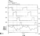
图9-11示出时序图和简化输入纹波的典型实施例。图9示出波形的同相集合。在此典型实施例中,示出四个下游降压变换器信号i(i1)、i(i2)、i(i3)和i(i4),这些信号分别对应于20A 3.3V、30A 2.5V、20A 1.8V和20A 1.2V调节器的输入电流。信号i(co)是输入电容器中的纹波电流。如图9所示,得到的电容器纹波电压是1.198V。图10示出不同相的效果。在此情况下,调节器相等地不同相。应指出,前面的两个波形重叠。在此情况下得到的电容器纹波电压是406mV。图11示出甚至更有利的定相分布,所述定相分布通过选择依赖于相移的电压和电流而产生。相应地,电容器纹波电压更低。在此情况下,电容器纹波为263mV。这清楚地显示能根据系统的工作点而选择相移以减小系统噪音的优点。应该理解,进一步的优化是有可能的。因而,使这些脉冲相移可导致更低的电容器纹波,或可替换地,需要更少量的总线电容来支持指定的纹波电压。Figures 9-11 show timing diagrams and simplified input ripple for typical embodiments. Figure 9 shows an in-phase set of waveforms. In this exemplary embodiment, four downstream buck converter signals i(i1), i(i2), i(i3) and i(i4) are shown, corresponding to 20A 3.3V, 30A 2.5V, 20A 1.8V and 20A 1.2V regulator input current. Signal i(co) is the ripple current in the input capacitor. As shown in Figure 9, the resulting capacitor ripple voltage is 1.198V. Figure 10 shows the effect of different phases. In this case the regulators are equally out of phase. It should be noted that the two preceding waveforms overlap. The resulting capacitor ripple voltage in this case is 406mV. Figure 11 shows an even more favorable phasing profile, which is produced by choosing voltage and current dependent on phase shift. Correspondingly, the capacitor ripple voltage is lower. In this case, the capacitor ripple is 263mV. This clearly shows the advantage of being able to choose the phase shift according to the operating point of the system to reduce system noise. It should be understood that further optimizations are possible. Thus, phase shifting these pulses may result in lower capacitor ripple, or alternatively, a smaller amount of bus capacitance is required to support a specified ripple voltage.
本发明容易实现各种变更和替代形式,并且,在本文中,借助附图中的实例详细地描述了本发明的特定实例。然而,应该理解,本发明不局限于公布的具体形式或方法,而相反,本发明涵盖所有在权利要求精神和范围内的变更、等效物和替代物。The present invention is susceptible to various modifications and substitutions, and, herein, specific examples of the present invention are described in detail by way of examples in the accompanying drawings. It should be understood, however, that the invention is not limited to the specific forms or methods disclosed, but on the contrary, the invention covers all modifications, equivalents, and alternatives falling within the spirit and scope of the claims.
Claims (26)
Applications Claiming Priority (2)
| Application Number | Priority Date | Filing Date | Title |
|---|---|---|---|
| US10/328,154 | 2002-12-23 | ||
| US10/328,154 US7373527B2 (en) | 2002-12-23 | 2002-12-23 | System and method for interleaving point-of-load regulators |
Publications (2)
| Publication Number | Publication Date |
|---|---|
| CN1685459A true CN1685459A (en) | 2005-10-19 |
| CN100459360C CN100459360C (en) | 2009-02-04 |
Family
ID=32594389
Family Applications (1)
| Application Number | Title | Priority Date | Filing Date |
|---|---|---|---|
| CNB2003801000206A Expired - Lifetime CN100459360C (en) | 2002-12-23 | 2003-11-06 | Systems and methods for interleaved point-of-load regulators |
Country Status (6)
| Country | Link |
|---|---|
| US (2) | US7373527B2 (en) |
| EP (1) | EP1576711B1 (en) |
| KR (1) | KR100785941B1 (en) |
| CN (1) | CN100459360C (en) |
| AU (1) | AU2003291357A1 (en) |
| WO (1) | WO2004062062A1 (en) |
Cited By (13)
| Publication number | Priority date | Publication date | Assignee | Title |
|---|---|---|---|---|
| CN101662212A (en) * | 2008-07-18 | 2010-03-03 | 英特赛尔美国股份有限公司 | Active droop current sharing |
| CN101686013A (en) * | 2008-07-18 | 2010-03-31 | 英特赛尔美国股份有限公司 | Intelligent management of current sharing groups |
| CN102025284A (en) * | 2009-09-10 | 2011-04-20 | 台达电子工业股份有限公司 | Interleaved pulse width modulation controlled power module system and method of operation thereof |
| CN102037427A (en) * | 2007-10-30 | 2011-04-27 | 大动力公司 | System for controlling an array of point-of-load regulators and auxiliary devices |
| CN102110069A (en) * | 2009-12-23 | 2011-06-29 | 英特尔公司 | Time negotiation using serial voltage identification communication |
| CN101589540B (en) * | 2007-01-24 | 2012-02-01 | 丰田自动车株式会社 | Multi-phase voltage conversion device, vehicle and control method for multi-phase voltage conversion device |
| CN102792573A (en) * | 2010-06-15 | 2012-11-21 | 动力威盛公司 | A digital stress share method |
| CN103444064A (en) * | 2010-12-23 | 2013-12-11 | 法雷奥电机控制系统公司 | Device and method for DC/DC conversion in the onboard network of a vehicle |
| CN103647271A (en) * | 2008-07-18 | 2014-03-19 | 英特赛尔美国股份有限公司 | Active droop current sharing |
| CN104953828A (en) * | 2014-03-31 | 2015-09-30 | 英飞凌科技奥地利有限公司 | Digital voltage regulator controller with multiple configurations |
| US9419526B2 (en) | 2012-03-16 | 2016-08-16 | Apple Inc. | Phase-shifting a synchronization signal to reduce electromagnetic interference |
| CN107908269A (en) * | 2017-11-30 | 2018-04-13 | 郑州云海信息技术有限公司 | A kind of more POL parallel combinations electric power systems and method of supplying power to |
| CN110531819A (en) * | 2018-05-25 | 2019-12-03 | 瑞萨电子美国有限公司 | Multiphase digital voltage regulator automatically configures |
Families Citing this family (86)
| Publication number | Priority date | Publication date | Assignee | Title |
|---|---|---|---|---|
| US7049798B2 (en) * | 2002-11-13 | 2006-05-23 | Power-One, Inc. | System and method for communicating with a voltage regulator |
| US6949916B2 (en) * | 2002-11-12 | 2005-09-27 | Power-One Limited | System and method for controlling a point-of-load regulator |
| US7394445B2 (en) * | 2002-11-12 | 2008-07-01 | Power-One, Inc. | Digital power manager for controlling and monitoring an array of point-of-load regulators |
| US7456617B2 (en) | 2002-11-13 | 2008-11-25 | Power-One, Inc. | System for controlling and monitoring an array of point-of-load regulators by a host |
| US6833691B2 (en) | 2002-11-19 | 2004-12-21 | Power-One Limited | System and method for providing digital pulse width modulation |
| US7249267B2 (en) * | 2002-12-21 | 2007-07-24 | Power-One, Inc. | Method and system for communicating filter compensation coefficients for a digital power control system |
| US7743266B2 (en) | 2002-12-21 | 2010-06-22 | Power-One, Inc. | Method and system for optimizing filter compensation coefficients for a digital power control system |
| US7673157B2 (en) | 2002-12-21 | 2010-03-02 | Power-One, Inc. | Method and system for controlling a mixed array of point-of-load regulators through a bus translator |
| US7737961B2 (en) | 2002-12-21 | 2010-06-15 | Power-One, Inc. | Method and system for controlling and monitoring an array of point-of-load regulators |
| US7266709B2 (en) | 2002-12-21 | 2007-09-04 | Power-One, Inc. | Method and system for controlling an array of point-of-load regulators and auxiliary devices |
| US7882372B2 (en) | 2002-12-21 | 2011-02-01 | Power-One, Inc. | Method and system for controlling and monitoring an array of point-of-load regulators |
| US7373527B2 (en) | 2002-12-23 | 2008-05-13 | Power-One, Inc. | System and method for interleaving point-of-load regulators |
| US7023190B2 (en) * | 2003-02-10 | 2006-04-04 | Power-One, Inc. | ADC transfer function providing improved dynamic regulation in a switched mode power supply |
| US7710092B2 (en) * | 2003-02-10 | 2010-05-04 | Power-One, Inc. | Self tracking ADC for digital power supply control systems |
| US6936999B2 (en) * | 2003-03-14 | 2005-08-30 | Power-One Limited | System and method for controlling output-timing parameters of power converters |
| US7080265B2 (en) * | 2003-03-14 | 2006-07-18 | Power-One, Inc. | Voltage set point control scheme |
| US7653757B1 (en) * | 2004-08-06 | 2010-01-26 | Zilker Labs, Inc. | Method for using a multi-master multi-slave bus for power management |
| US7506179B2 (en) | 2003-04-11 | 2009-03-17 | Zilker Labs, Inc. | Method and apparatus for improved DC power delivery management and configuration |
| US7793005B1 (en) * | 2003-04-11 | 2010-09-07 | Zilker Labs, Inc. | Power management system using a multi-master multi-slave bus and multi-function point-of-load regulators |
| US7685320B1 (en) * | 2003-04-11 | 2010-03-23 | Zilker Labs, Inc. | Autonomous sequencing and fault spreading |
| US7372682B2 (en) * | 2004-02-12 | 2008-05-13 | Power-One, Inc. | System and method for managing fault in a power system |
| US20050286709A1 (en) * | 2004-06-28 | 2005-12-29 | Steve Horton | Customer service marketing |
| US7554310B2 (en) * | 2005-03-18 | 2009-06-30 | Power-One, Inc. | Digital double-loop output voltage regulation |
| US7141956B2 (en) * | 2005-03-18 | 2006-11-28 | Power-One, Inc. | Digital output voltage regulation circuit having first control loop for high speed and second control loop for high accuracy |
| US7239115B2 (en) * | 2005-04-04 | 2007-07-03 | Power-One, Inc. | Digital pulse width modulation controller with preset filter coefficients |
| EP1875592A1 (en) | 2005-04-14 | 2008-01-09 | Koninklijke Philips Electronics N.V. | Communication in phase shifted driven power converters |
| US7327149B2 (en) * | 2005-05-10 | 2008-02-05 | Power-One, Inc. | Bi-directional MOS current sense circuit |
| US8589704B2 (en) * | 2005-06-16 | 2013-11-19 | Active-Semi, Inc. | System for a scalable and programmable power management integrated circuit |
| US7688046B2 (en) * | 2005-07-25 | 2010-03-30 | Apple Inc. | Power converters having varied switching frequencies |
| US8515342B2 (en) * | 2005-10-12 | 2013-08-20 | The Directv Group, Inc. | Dynamic current sharing in KA/KU LNB design |
| US20080018313A1 (en) * | 2006-07-20 | 2008-01-24 | International Business Machines Corporation | Power supply system using delay lines in regulator topology to reduce input ripple voltage |
| US20080246453A1 (en) * | 2006-07-20 | 2008-10-09 | International Business Machines Corporation | Power supply system using delay lines in regulator topology to reduce input ripple voltage |
| KR100817031B1 (en) * | 2006-08-25 | 2008-03-26 | 주식회사 케이이씨 | Single wire serial communication module |
| US7847532B2 (en) | 2007-01-19 | 2010-12-07 | Astec International Limited | Centralized controller and power manager for on-board power systems |
| US7673084B2 (en) * | 2007-02-20 | 2010-03-02 | Infineon Technologies Ag | Bus system and methods of operation using a combined data and synchronization line to communicate between bus master and slaves |
| US7755341B2 (en) * | 2007-07-05 | 2010-07-13 | Intersil Americas Inc. | Steady state frequency control of variable frequency switching regulators |
| US7592791B2 (en) * | 2007-08-07 | 2009-09-22 | Newport Media, Inc. | High efficiency DC-DC converter using pulse skipping modulation with programmable burst duration |
| US7834613B2 (en) * | 2007-10-30 | 2010-11-16 | Power-One, Inc. | Isolated current to voltage, voltage to voltage converter |
| DE102007059380B3 (en) * | 2007-12-07 | 2009-05-07 | Deutsches Zentrum für Luft- und Raumfahrt e.V. | Ripple currents minimizing method for common buffer capacitor of e.g. step-up converter, involves adjusting determined phase difference of signal during pulse width modulation period after processing pulses in another period |
| US8120205B2 (en) * | 2008-07-18 | 2012-02-21 | Zilker Labs, Inc. | Adding and dropping phases in current sharing |
| DE102008002971A1 (en) * | 2008-07-25 | 2009-01-15 | Robust Electronics Gmbh | Method for minimizing harmonic source current during supply from multiple converter stages, involves determining amplitude and phase of fundamental vibrations of each converter |
| DE102008048017B4 (en) * | 2008-09-19 | 2023-03-16 | Bayerische Motoren Werke Aktiengesellschaft | Control device for a polyphase voltage converter |
| DE102008053670A1 (en) | 2008-10-29 | 2010-05-12 | Texas Instruments Deutschland Gmbh | Apparatus and method for generating clock signals for DC-DC converters |
| GB2471078A (en) * | 2009-06-15 | 2010-12-22 | Powervation Ltd | Digitally sharing of power converter stress |
| US9014825B2 (en) * | 2009-06-16 | 2015-04-21 | Maxim Integrated Products, Inc. | System and method for sequentially distributing power among one or more modules |
| SG177602A1 (en) * | 2009-07-10 | 2012-03-29 | Protonex Technology Corp | Power managers, methods for operating a power manager, and methods for operating a power network |
| TWI412216B (en) * | 2009-09-02 | 2013-10-11 | Delta Electronics Inc | Interleaved-pwm power system and method for operating the same |
| US8014181B2 (en) * | 2009-09-29 | 2011-09-06 | General Electric Company | Power conversion control system |
| TWI381622B (en) * | 2009-10-05 | 2013-01-01 | Anpec Electronics Corp | Power supply with synchronized clocks and related dc-dc converter |
| US8502420B1 (en) | 2009-10-15 | 2013-08-06 | Power-One, Inc. | Power supply architecture for controlling and monitoring isolated output modules |
| US8261103B2 (en) * | 2009-10-28 | 2012-09-04 | Dell Products L.P. | Systems and methods for controlling power delivery to system components |
| US8080981B2 (en) * | 2009-11-06 | 2011-12-20 | Delta Electronics, Inc. | Interleaved-PWM power module system and method with phase-locking operation |
| EP2394908B1 (en) * | 2010-06-08 | 2013-03-06 | GE Energy Power Conversion Technology Limited | Power distribution system and method for controlling it. |
| US8575909B2 (en) * | 2010-09-17 | 2013-11-05 | Qualcomm Incorporated | Synchronously sampled single bit switch mode power supply |
| US8723492B2 (en) * | 2011-03-22 | 2014-05-13 | Integrated Device Technology, Inc. | Autonomous controlled headroom low dropout regulator for single inductor multiple output power supply |
| TWI481169B (en) * | 2011-05-27 | 2015-04-11 | Leadtrend Tech Corp | Method for controlling voltage crossing power switch of switched-mode power converter and the circuit using the same |
| US8760193B2 (en) | 2011-07-01 | 2014-06-24 | Tabula, Inc. | Configurable storage elements |
| US9148151B2 (en) | 2011-07-13 | 2015-09-29 | Altera Corporation | Configurable storage elements |
| JP5849502B2 (en) * | 2011-08-01 | 2016-01-27 | ソニー株式会社 | Information processing apparatus, information processing method, and program |
| JP5878742B2 (en) * | 2011-11-30 | 2016-03-08 | ルネサスエレクトロニクス株式会社 | controller |
| US8935010B1 (en) * | 2011-12-13 | 2015-01-13 | Juniper Networks, Inc. | Power distribution within high-power networking equipment |
| US8624567B2 (en) * | 2011-12-30 | 2014-01-07 | O2Micro, Inc. | Controllers for DC/DC converters |
| KR101319989B1 (en) * | 2012-04-25 | 2013-10-18 | 한국에너지기술연구원 | Apparatus and method for controlling plural power converting modules, and apparatus and method for analizing electric energy imbalance |
| US9030047B2 (en) | 2012-06-08 | 2015-05-12 | International Business Machines Corporation | Controlling a fault-tolerant array of converters |
| US9325242B2 (en) * | 2012-06-29 | 2016-04-26 | Infineon Technologies Austria Ag | Switching regulator output capacitor current estimation |
| WO2014007845A1 (en) * | 2012-07-02 | 2014-01-09 | Tabula, Inc. | Configurable storage elements |
| KR102008810B1 (en) * | 2012-11-12 | 2019-08-08 | 엘지이노텍 주식회사 | Wireless power transmitting apparatus and method |
| US9368073B2 (en) * | 2013-08-12 | 2016-06-14 | Shenzhen China Star Optoelectronics Technology Co., Ltd. | LED backlight driving circuit and LCD |
| US9665147B1 (en) * | 2013-12-12 | 2017-05-30 | Google Inc. | Devices and methods for minimizing input capacitance in computer design |
| US9570983B2 (en) * | 2014-04-22 | 2017-02-14 | International Business Machines Corporation | Point of load regulator synchronization and phase offset |
| US9946677B2 (en) * | 2015-02-12 | 2018-04-17 | Atmel Corporation | Managing single-wire communications |
| US9806620B2 (en) * | 2015-03-12 | 2017-10-31 | Avago Technologies General Ip (Singapore) Pte. Ltd. | Multi-phase hysteretic buck switching regulator |
| US9660627B1 (en) | 2016-01-05 | 2017-05-23 | Bitfury Group Limited | System and techniques for repeating differential signals |
| US9514264B1 (en) | 2016-01-05 | 2016-12-06 | Bitfury Group Limited | Layouts of transmission gates and related systems and techniques |
| US9645604B1 (en) | 2016-01-05 | 2017-05-09 | Bitfury Group Limited | Circuits and techniques for mesochronous processing |
| US10008918B2 (en) | 2016-10-25 | 2018-06-26 | Dialog Semiconductor (Uk) Limited | Phase-shifting optimization for asymmetric inductors in multi-phase DC-DC converters |
| US10230236B2 (en) * | 2017-05-04 | 2019-03-12 | Thermo King Corporation | Method and system for feedback-based load control of a climate control system in transport |
| KR102395035B1 (en) | 2017-08-29 | 2022-05-13 | 삼성전자 주식회사 | Power supply for compensating for current deviation and operating method thereof |
| CN109683694A (en) * | 2018-12-26 | 2019-04-26 | 联想(北京)有限公司 | A kind of control method, device and electronic equipment |
| CN109491490B (en) * | 2018-12-26 | 2021-05-18 | 联想(北京)有限公司 | Control method and device and electronic equipment |
| EP3709492B1 (en) | 2019-03-14 | 2021-08-11 | Nxp B.V. | Distributed control of a multiphase power converter |
| CN109933180B (en) * | 2019-03-22 | 2021-06-15 | 联想(北京)有限公司 | Control method and device and electronic equipment |
| EP3832871B1 (en) | 2019-12-03 | 2022-10-26 | NXP USA, Inc. | Distributed interleaving control of multiphase smpcs |
| EP3902132B1 (en) * | 2020-04-22 | 2024-06-05 | NXP USA, Inc. | Modular interleaving techniques for scalable power electronics converter |
| US11942959B2 (en) * | 2021-09-28 | 2024-03-26 | Infineon Technologies Ag | Calibration with feedback sensing |
| KR20230155260A (en) | 2022-05-03 | 2023-11-10 | 삼성전자주식회사 | A power control integrated circuit |
Family Cites Families (208)
| Publication number | Priority date | Publication date | Assignee | Title |
|---|---|---|---|---|
| US142513A (en) * | 1873-09-02 | Improvement m draft-tubes for soda-fountains | ||
| US201761A (en) * | 1878-03-26 | Improvement in motors | ||
| US429581A (en) * | 1890-06-03 | parmelee | ||
| US73347A (en) * | 1868-01-14 | of same place | ||
| US122429A (en) * | 1872-01-02 | Improvement in propelling canal-boats | ||
| US27101A (en) * | 1860-02-14 | Twine-holdek | ||
| US33152A (en) * | 1861-08-27 | Improvement in combination cement and metal pipes | ||
| US3660672A (en) | 1971-02-25 | 1972-05-02 | Pioneer Magnetics Inc | Power supply dual output |
| GB1536046A (en) | 1976-06-30 | 1978-12-20 | Ibm | Data processing system power control |
| US4194147A (en) | 1977-12-05 | 1980-03-18 | Burr-Brown Research Corporation | Parallel connected switching regulator system |
| DE2904786C2 (en) | 1979-02-08 | 1981-02-19 | Siemens Ag, 1000 Berlin Und 8000 Muenchen | Process for regulating inverters in parallel operation and circuit arrangements for carrying out the process |
| US4335445A (en) | 1979-02-26 | 1982-06-15 | Kepco, Inc. | System for interfacing computers with programmable power supplies |
| US4350943A (en) | 1980-04-04 | 1982-09-21 | Pritchard Eric K | Amplifier for inductive loads with corrective current sensing |
| US4451773A (en) | 1982-04-02 | 1984-05-29 | Bell Telephone Laboratories, Incorporated | Rectifier control system for a DC power plant system |
| DE3369778D1 (en) | 1982-06-04 | 1987-03-12 | Nippon Chemicon | Power supply device |
| US4538073A (en) | 1983-05-09 | 1985-08-27 | Convergent Technologies, Inc. | Modular power supply system |
| US4607330A (en) | 1983-11-29 | 1986-08-19 | Parallel Computers, Inc. | Fault-tolerant power supply system |
| US4622627A (en) | 1984-02-16 | 1986-11-11 | Theta-J Corporation | Switching electrical power supply utilizing miniature inductors integrally in a PCB |
| JPS60244111A (en) | 1984-05-18 | 1985-12-04 | Nec Corp | Digital filter circuit |
| US4677566A (en) | 1984-10-18 | 1987-06-30 | Burroughs Corporation | Power control network for multiple digital modules |
| US4654769A (en) | 1984-11-02 | 1987-03-31 | California Institute Of Technology | Transformerless dc-to-dc converters with large conversion ratios |
| US4616142A (en) | 1984-12-31 | 1986-10-07 | Sundstrand Corporation | Method of operating parallel-connected semiconductor switch elements |
| US4630187A (en) | 1985-09-09 | 1986-12-16 | Sperry Corporation | Power converter with duty ratio quantization |
| SU1359874A1 (en) | 1985-10-14 | 1987-12-15 | Специальное Конструкторское Бюро Телевизионной Аппаратуры Симферопольского Производственного Объединения "Фотон" | D.c.voltage converter |
| CA1295014C (en) | 1986-08-01 | 1992-01-28 | Christopher Paul Henze | Digitally controlled a.c. to d.c. power conditioner that draws sinusoidal input current |
| US4761725A (en) | 1986-08-01 | 1988-08-02 | Unisys Corporation | Digitally controlled A.C. to D.C. power conditioner |
| US4766364A (en) * | 1987-11-04 | 1988-08-23 | International Business Machines Corporation | Parallel power systems |
| US5168208A (en) | 1988-05-09 | 1992-12-01 | Onan Corporation | Microprocessor based integrated generator set controller apparatus and method |
| US4988942A (en) | 1988-11-08 | 1991-01-29 | Spectra-Physics, Inc. | Switched resistor regulator control when transfer function includes discontinuity |
| DE3918866A1 (en) | 1989-06-09 | 1990-12-13 | Blaupunkt Werke Gmbh | ARRANGEMENT FOR CONVERTING A SIGNAL WITH A FIRST SAMPLE RATE INTO A SIGNAL WITH A SECOND SAMPLE RATE |
| US5053920A (en) | 1989-06-09 | 1991-10-01 | Digital Equipment Corporation | Integrated power conversion |
| US4940930A (en) | 1989-09-07 | 1990-07-10 | Honeywell Incorporated | Digitally controlled current source |
| US5004972A (en) | 1989-12-26 | 1991-04-02 | Honeywell Inc. | Integrated power level control and on/off function circuit |
| FR2656932B1 (en) | 1990-01-09 | 1992-05-07 | Sgs Thomson Microelectronics | CURRENT MEASUREMENT CIRCUIT IN A POWER MOS TRANSISTOR. |
| US5270904A (en) | 1990-05-02 | 1993-12-14 | Zdzislaw Gulczynski | Switching power apparatus with 3-state driver |
| RU1814177C (en) | 1990-11-05 | 1993-05-07 | Киевский Политехнический Институт Им.50-Летия Великой Октябрьской Социалистической Революции | Voltage converter |
| US5073848A (en) | 1990-11-21 | 1991-12-17 | General Electric Company | Power distribution system |
| US5117430A (en) | 1991-02-08 | 1992-05-26 | International Business Machines Corporation | Apparatus and method for communicating between nodes in a network |
| US5079498A (en) | 1991-03-26 | 1992-01-07 | Vickers Systems Limited | Digital pulse-width-modulation generator for current control |
| US6115441A (en) | 1991-07-09 | 2000-09-05 | Dallas Semiconductor Corporation | Temperature detector systems and methods |
| DE4122945A1 (en) | 1991-07-11 | 1993-01-14 | Philips Patentverwaltung | MICROPROCESSOR CONTROLLED DC CONVERTER |
| US5229699A (en) | 1991-10-15 | 1993-07-20 | Industrial Technology Research Institute | Method and an apparatus for PID controller tuning |
| US5481140A (en) | 1992-03-10 | 1996-01-02 | Mitsubishi Denki Kabushiki Kaisha | Demand control apparatus and power distribution control system |
| GB9205995D0 (en) | 1992-03-19 | 1992-04-29 | Astec Int Ltd | A power supply |
| US5426425A (en) | 1992-10-07 | 1995-06-20 | Wescom, Inc. | Intelligent locator system with multiple bits represented in each pulse |
| JP2508616B2 (en) | 1992-12-21 | 1996-06-19 | 日本プレシジョン・サーキッツ株式会社 | Sampling rate converter |
| US5377090A (en) | 1993-01-19 | 1994-12-27 | Martin Marietta Corporation | Pulsed power converter with multiple output voltages |
| JP3191275B2 (en) | 1993-02-22 | 2001-07-23 | 横河電機株式会社 | Switching power supply |
| US5481178A (en) | 1993-03-23 | 1996-01-02 | Linear Technology Corporation | Control circuit and method for maintaining high efficiency over broad current ranges in a switching regulator circuit |
| US5489904A (en) | 1993-09-28 | 1996-02-06 | The Regents Of The University Of California | Analog current mode analog/digital converter |
| JP2833460B2 (en) | 1993-12-27 | 1998-12-09 | 株式会社日立製作所 | Power system |
| US6121760A (en) | 1994-03-17 | 2000-09-19 | Texas Instruments Incorporated | Turn-on controller for switch-mode regulator |
| US5532577A (en) | 1994-04-01 | 1996-07-02 | Maxim Integrated Products, Inc. | Method and apparatus for multiple output regulation in a step-down switching regulator |
| US5627460A (en) | 1994-12-28 | 1997-05-06 | Unitrode Corporation | DC/DC converter having a bootstrapped high side driver |
| US5949226A (en) | 1995-04-10 | 1999-09-07 | Kabushiki Kaisha Toyoda Jidoshokki Seisakush | DC/DC converter with reduced power consumpton and improved efficiency |
| US5727208A (en) | 1995-07-03 | 1998-03-10 | Dell U.S.A. L.P. | Method and apparatus for configuration of processor operating parameters |
| US5752047A (en) | 1995-08-11 | 1998-05-12 | Mcdonnell Douglas Corporation | Modular solid state power controller with microcontroller |
| US5646509A (en) | 1995-12-01 | 1997-07-08 | International Business Machines Corporation | Battery capacity test and electronic system utilizing same |
| US5631550A (en) | 1996-04-25 | 1997-05-20 | Lockheed Martin Tactical Defense Systems | Digital control for active power factor correction |
| US5675480A (en) | 1996-05-29 | 1997-10-07 | Compaq Computer Corporation | Microprocessor control of parallel power supply systems |
| US5943227A (en) | 1996-06-26 | 1999-08-24 | Fairchild Semiconductor Corporation | Programmable synchronous step down DC-DC converter controller |
| US5815018A (en) | 1996-07-16 | 1998-09-29 | Systech Solutions, Inc. | Pulse modulator circuit for an illuminator system |
| JP3042423B2 (en) | 1996-09-30 | 2000-05-15 | 日本電気株式会社 | Series-parallel A / D converter |
| US5929620A (en) | 1996-11-07 | 1999-07-27 | Linear Technology Corporation | Switching regulators having a synchronizable oscillator frequency with constant ramp amplitude |
| US5847950A (en) | 1997-02-19 | 1998-12-08 | Electronic Measurements, Inc. | Control system for a power supply |
| US5889392A (en) | 1997-03-06 | 1999-03-30 | Maxim Integrated Products, Inc. | Switch-mode regulators and methods providing transient response speed-up |
| US5892933A (en) | 1997-03-31 | 1999-04-06 | Compaq Computer Corp. | Digital bus |
| US5872984A (en) | 1997-04-01 | 1999-02-16 | International Business Machines Corporation | Uninterruptible power supply providing continuous power mainstore function for a computer system |
| US5946495A (en) | 1997-04-08 | 1999-08-31 | Compaq Computer Corp. | Data communication circuit for controlling data communication between redundant power supplies and peripheral devices |
| US5933453A (en) | 1997-04-29 | 1999-08-03 | Hewlett-Packard Company | Delta-sigma pulse width modulator control circuit |
| US5905370A (en) | 1997-05-06 | 1999-05-18 | Fairchild Semiconductor Corporation | Programmable step down DC-DC converter controller |
| US5883797A (en) | 1997-06-30 | 1999-03-16 | Power Trends, Inc. | Parallel path power supply |
| US5917719A (en) | 1997-08-11 | 1999-06-29 | Power Ten, Inc. | Internally programmable modular power supply and method |
| US5935252A (en) | 1997-08-18 | 1999-08-10 | International Business Machines Corporation | Apparatus and method for determining and setting system device configuration relating to power and cooling using VPD circuits associated with system devices |
| US6000042A (en) | 1997-08-25 | 1999-12-07 | 3Com Corporation | Fault detection on a dual supply system for a universal serial bus system |
| US6005377A (en) | 1997-09-17 | 1999-12-21 | Lucent Technologies Inc. | Programmable digital controller for switch mode power conversion and power supply employing the same |
| US5870296A (en) | 1997-10-14 | 1999-02-09 | Maxim Integrated Products, Inc. | Dual interleaved DC to DC switching circuits realized in an integrated circuit |
| US6079026A (en) | 1997-12-11 | 2000-06-20 | International Business Machines Corporation | Uninterruptible memory backup power supply system using threshold value of energy in the backup batteries for control of switching from AC to DC output |
| US5990669A (en) | 1997-12-15 | 1999-11-23 | Dell Usa, L.P. | Voltage supply regulation using master/slave timer circuit modulation |
| US6136143A (en) | 1998-02-23 | 2000-10-24 | 3M Innovative Properties Company | Surface treating article including a hub |
| JP3744680B2 (en) | 1998-03-31 | 2006-02-15 | 富士通株式会社 | Power supply device and method for controlling power supply circuit |
| JP3702091B2 (en) | 1998-03-31 | 2005-10-05 | 富士通株式会社 | Power supply device and method for controlling power supply circuit |
| FI107418B (en) | 1998-05-22 | 2001-07-31 | Muuntolaite Oy | Method and plant for controlling a power source system |
| US6199130B1 (en) | 1998-06-04 | 2001-03-06 | International Business Machines Corporation | Concurrent maintenance for PCI based DASD subsystem with concurrent maintenance message being communicated between SPCN (system power control network) and I/O adapter using PCI bridge |
| US5929618A (en) | 1998-06-04 | 1999-07-27 | Lucent Technologies Inc. | System and method for synchronizing and interleaving power modules |
| US6055163A (en) | 1998-08-26 | 2000-04-25 | Northrop Grumman Corporation | Communications processor remote host and multiple unit control devices and methods for micropower generation systems |
| US6177787B1 (en) | 1998-09-11 | 2001-01-23 | Linear Technology Corporation | Circuits and methods for controlling timing and slope compensation in switching regulators |
| US6304823B1 (en) | 1998-09-16 | 2001-10-16 | Microchip Technology Incorporated | Microprocessor power supply system including a programmable power supply and a programmable brownout detector |
| US6268716B1 (en) | 1998-10-30 | 2001-07-31 | Volterra Semiconductor Corporation | Digital voltage regulator using current control |
| US6198261B1 (en) | 1998-10-30 | 2001-03-06 | Volterra Semiconductor Corporation | Method and apparatus for control of a power transistor in a digital voltage regulator |
| US6100676A (en) | 1998-10-30 | 2000-08-08 | Volterra Semiconductor Corporation | Method and apparatus for digital voltage regulation |
| DE19850125B4 (en) | 1998-10-30 | 2007-06-28 | Siemens Ag | Power supply for power supply of a bus |
| US6181029B1 (en) | 1998-11-06 | 2001-01-30 | International Business Machines Corporation | Method of controlling battery back-up for multiple power supplies |
| US6163178A (en) | 1998-12-28 | 2000-12-19 | Rambus Incorporated | Impedance controlled output driver |
| US6021059A (en) | 1998-12-31 | 2000-02-01 | Honeywell Inc. | Integrated synchronous rectifier for power supplies |
| WO2000044098A1 (en) | 1999-01-19 | 2000-07-27 | Steensgaard Madsen Jesper | Residue-compensating a / d converter |
| US6137280A (en) | 1999-01-22 | 2000-10-24 | Science Applications International Corporation | Universal power manager with variable buck/boost converter |
| US6184659B1 (en) | 1999-02-16 | 2001-02-06 | Microchip Technology Incorporated | Microcontroller with integral switch mode power supply controller |
| US6355990B1 (en) | 1999-03-24 | 2002-03-12 | Rockwell Collins, Inc. | Power distribution system and method |
| US6111396A (en) | 1999-04-15 | 2000-08-29 | Vanguard International Semiconductor Corporation | Any value, temperature independent, voltage reference utilizing band gap voltage reference and cascode current mirror circuits |
| US6917186B2 (en) | 2000-04-24 | 2005-07-12 | S & C Electric Co. | Monitoring and control for power electronic system |
| JP3644531B2 (en) | 1999-07-06 | 2005-04-27 | 富士電機機器制御株式会社 | Arm-on detection circuit for on-delay compensation |
| US6057607A (en) | 1999-07-16 | 2000-05-02 | Semtech Corporation | Method and apparatus for voltage regulation in multi-output switched mode power supplies |
| US6191566B1 (en) | 1999-08-26 | 2001-02-20 | Lucent Technologies Inc. | Board mountable power supply module with multi-function control pin |
| US6294954B1 (en) | 1999-09-23 | 2001-09-25 | Audiologic, Incorporated | Adaptive dead time control for switching circuits |
| US6157093A (en) | 1999-09-27 | 2000-12-05 | Philips Electronics North America Corporation | Modular master-slave power supply controller |
| US6211579B1 (en) | 1999-09-29 | 2001-04-03 | Lucent Technologies, Inc. | Multiple output converter having a low power dissipation cross regulation compensation circuit |
| US6392577B1 (en) | 1999-10-05 | 2002-05-21 | Stmicroelectronics, Inc. | System and method for regulating an alternator |
| US6465993B1 (en) | 1999-11-01 | 2002-10-15 | John Clarkin | Voltage regulation employing a composite feedback signal |
| US6208127B1 (en) | 1999-11-02 | 2001-03-27 | Maxim Integrated Products, Inc. | Methods and apparatus to predictably change the output voltage of regulators |
| AU2001233095A1 (en) | 2000-01-27 | 2001-08-07 | Primarion, Inc. | Apparatus for providing regulated power to an integrated circuit |
| US6396169B1 (en) | 2000-02-29 | 2002-05-28 | 3Com Corporation | Intelligent power supply control for electronic systems requiring multiple voltages |
| US6385024B1 (en) | 2000-03-07 | 2002-05-07 | Ss8 Networks, Inc. | System and method for monitoring current consumption from current share components |
| US6246219B1 (en) | 2000-03-24 | 2001-06-12 | The Boeing Company | String switching apparatus and associated method for controllably connecting the output of a solar array string to a respective power bus |
| US6291975B1 (en) | 2000-03-27 | 2001-09-18 | Rockwell Collins | Method and system for efficiently regulating power supply voltages with reduced propagation of power transients capable of communicating information |
| US6150803A (en) | 2000-03-28 | 2000-11-21 | Linear Technology Corporation | Dual input, single output power supply |
| US6373334B1 (en) | 2000-06-12 | 2002-04-16 | Cirrus Logic, Inc. | Real time correction of a digital PWM amplifier |
| US20010052862A1 (en) | 2000-06-20 | 2001-12-20 | Koninklijke Philips Electronics N.V. | Security system simulates patterns of usage of appliances |
| US6249111B1 (en) | 2000-06-22 | 2001-06-19 | Intel Corporation | Dual drive buck regulator |
| US6448746B1 (en) * | 2000-06-30 | 2002-09-10 | Intel Corporation | Multiple phase voltage regulator system |
| US6465909B1 (en) | 2000-07-31 | 2002-10-15 | Linear Technology Corporation | Circuits and methods for controlling load sharing by multiple power supplies |
| US6396250B1 (en) | 2000-08-31 | 2002-05-28 | Texas Instruments Incorporated | Control method to reduce body diode conduction and reverse recovery losses |
| IT1318879B1 (en) * | 2000-09-19 | 2003-09-10 | St Microelectronics Srl | VOLTAGE / CURRENT CONTROLLER DEVICE, IN PARTICULAR SWITCHING INTERLEAVING REGULATORS. |
| US6320768B1 (en) | 2000-10-06 | 2001-11-20 | Texas Instruments Incorporated | Power supply pulse width modulation (PWM) control system |
| AU2002211583A1 (en) | 2000-10-10 | 2002-04-22 | Primarion, Inc. | System and method for highly phased power regulation |
| US7007176B2 (en) * | 2000-10-10 | 2006-02-28 | Primarion, Inc. | System and method for highly phased power regulation using adaptive compensation control |
| AU2002213260A1 (en) | 2000-10-13 | 2002-04-22 | Primarion, Inc. | System and method for highly phased power regulation using adaptive compensation control |
| IT1319007B1 (en) | 2000-10-16 | 2003-09-19 | St Microelectronics Srl | MANAGEMENT SYSTEM OF A PLURALITY OF VRM MODULES AND RELATED SYNCHRONIZATION METHODS |
| US6735706B2 (en) | 2000-12-06 | 2004-05-11 | Lattice Semiconductor Corporation | Programmable power management system and method |
| US6654264B2 (en) | 2000-12-13 | 2003-11-25 | Intel Corporation | System for providing a regulated voltage with high current capability and low quiescent current |
| EP1215808B1 (en) * | 2000-12-13 | 2011-05-11 | Semiconductor Components Industries, LLC | A power supply circuit and method thereof to detect demagnitization of the power supply |
| DE60144025D1 (en) | 2000-12-20 | 2011-03-24 | Thomson Licensing | I2C BUS CONTROL FOR INSULATION OF SELECTED ICS FOR QUICK I2C TRANSMISSION |
| TW554605B (en) | 2000-12-20 | 2003-09-21 | Delta Electronics Inc | Output voltage adjustable electrical power switcher |
| US6421259B1 (en) | 2000-12-28 | 2002-07-16 | International Business Machines Corporation | Modular DC distribution system for providing flexible power conversion scalability within a power backplane between an AC source and low voltage DC outputs |
| US6411071B1 (en) | 2000-12-29 | 2002-06-25 | Volterra Semiconductor Corporation | Lag compensating controller having an improved transient response |
| US6828765B1 (en) | 2000-12-29 | 2004-12-07 | Volterra Semiconductor Corporation | Method and computer program product for improved transient response |
| US6686831B2 (en) | 2001-01-23 | 2004-02-03 | Invensys Systems, Inc. | Variable power control for process control instruments |
| US6947273B2 (en) | 2001-01-29 | 2005-09-20 | Primarion, Inc. | Power, ground, and routing scheme for a microprocessor power regulator |
| US6965502B2 (en) | 2001-03-21 | 2005-11-15 | Primarion, Inc. | System, device and method for providing voltage regulation to a microelectronic device |
| US6791302B2 (en) | 2001-03-21 | 2004-09-14 | Primarion, Inc. | Methods and apparatus for open-loop enhanced control of power supply transients |
| US6975494B2 (en) | 2001-01-29 | 2005-12-13 | Primarion, Inc. | Method and apparatus for providing wideband power regulation to a microelectronic device |
| US6366069B1 (en) * | 2001-02-01 | 2002-04-02 | Intel Corporation | Hysteretic-mode multi-phase switching regulator |
| US6800957B2 (en) | 2001-02-06 | 2004-10-05 | General Electric Company | Electronic distribution system for 36V automobiles |
| TW575949B (en) | 2001-02-06 | 2004-02-11 | Hitachi Ltd | Mixed integrated circuit device, its manufacturing method and electronic apparatus |
| US6400127B1 (en) | 2001-02-12 | 2002-06-04 | Philips Electronics North America Corporation | Dual mode pulse-width modulator for power control applications |
| JP2002269925A (en) | 2001-03-09 | 2002-09-20 | Matsushita Electric Ind Co Ltd | Optical disc playback device |
| TW556396B (en) | 2001-03-22 | 2003-10-01 | Primarion Inc | Power regulation system, apparatus, and method for providing regulated power to a microelectronic device |
| ATE328391T1 (en) | 2001-03-26 | 2006-06-15 | Harman Int Ind | PULSE WIDTH MODULATION AMPLIFIER WITH DIGITAL SIGNAL PROCESSOR |
| US6731023B2 (en) * | 2001-03-29 | 2004-05-04 | Autoliv Asp, Inc. | Backup power supply for restraint control module |
| US20040225811A1 (en) | 2001-04-04 | 2004-11-11 | Fosler Ross M. | Digital addressable lighting interface bridge |
| US6476589B2 (en) | 2001-04-06 | 2002-11-05 | Linear Technology Corporation | Circuits and methods for synchronizing non-constant frequency switching regulators with a phase locked loop |
| US6411072B1 (en) | 2001-04-17 | 2002-06-25 | Honeywell International Inc. | PWM power supply with constant RMS output voltage control |
| US6469478B1 (en) | 2001-04-23 | 2002-10-22 | Artesyn Technologies, Inc. | Multiple output power supply including one regulated converter and at least one semi-regulated converter |
| US6816758B2 (en) | 2001-04-26 | 2004-11-09 | The Boeing Company | Programmable controller for remotely controlling input power through a switch to a load and an associated method of operation |
| US6621259B2 (en) | 2001-05-30 | 2003-09-16 | Texas Instruments Incorporated | Current sense amplifier and method |
| US6788035B2 (en) | 2001-06-12 | 2004-09-07 | Primarion, Inc. | Serial bus control method and apparatus for a microelectronic power regulation system |
| US6915440B2 (en) | 2001-06-12 | 2005-07-05 | International Business Machines Corporation | Apparatus, program product and method of performing power fault analysis in a computer system |
| US6744243B2 (en) | 2001-06-28 | 2004-06-01 | Texas Instruments Incorporated | System and method for dynamically regulating a step down power supply |
| GB2377094B (en) | 2001-06-29 | 2003-07-30 | Paul Morris | Power converter |
| US6928560B1 (en) | 2001-09-28 | 2005-08-09 | Unisys Corporation | Distributed power control system |
| US6577258B2 (en) | 2001-10-01 | 2003-06-10 | Nokia Corporation | Adaptive sigma-delta data converter for mobile terminals |
| US6795009B2 (en) | 2002-09-09 | 2004-09-21 | Primarion, Inc. | System and method for current handling in a digitally-controlled power converter |
| US6791298B2 (en) | 2001-11-05 | 2004-09-14 | Shakti Systems, Inc. | Monolithic battery charging device |
| CN2521825Y (en) | 2001-11-20 | 2002-11-20 | 罗代云 | Novel digital audio power amplifier |
| US7554828B2 (en) | 2001-12-03 | 2009-06-30 | Igo, Inc. | Power converter with retractable cable system |
| US6807070B2 (en) | 2001-12-12 | 2004-10-19 | International Rectifier Corporation | Resonant converter with phase delay control |
| US6903949B2 (en) | 2001-12-12 | 2005-06-07 | International Rectifier Corporation | Resonant converter with phase delay control |
| US6717389B1 (en) | 2001-12-21 | 2004-04-06 | Unisys Corporation | Method and apparatus for current controlled transient reduction in a voltage regulator |
| US20030122429A1 (en) | 2001-12-28 | 2003-07-03 | Zhang Kevin X. | Method and apparatus for providing multiple supply voltages for a processor |
| US6448745B1 (en) | 2002-01-08 | 2002-09-10 | Dialog Semiconductor Gmbh | Converter with inductor and digital controlled timing |
| US6930893B2 (en) | 2002-01-31 | 2005-08-16 | Vlt, Inc. | Factorized power architecture with point of load sine amplitude converters |
| US6975098B2 (en) | 2002-01-31 | 2005-12-13 | Vlt, Inc. | Factorized power architecture with point of load sine amplitude converters |
| US6897636B2 (en) | 2002-03-29 | 2005-05-24 | Intersil Americas Inc. | Method and circuit for scaling and balancing input and output currents in a multi-phase DC-DC converter using different input voltages |
| US6829547B2 (en) | 2002-04-29 | 2004-12-07 | Tektronix, Inc. | Measurement test instrument and associated voltage management system for accessory device |
| SE0201432D0 (en) | 2002-04-29 | 2002-05-13 | Emerson Energy Systems Ab | A Power supply system and apparatus |
| US6850426B2 (en) | 2002-04-30 | 2005-02-01 | Honeywell International Inc. | Synchronous and bi-directional variable frequency power conversion systems |
| KR200284495Y1 (en) | 2002-05-10 | 2002-08-03 | 로보랜드(주) | Driving Module of Servo-Motor for Robot |
| US6693811B1 (en) | 2002-07-02 | 2004-02-17 | Tyco Electronics Power Systems, Inc. | Integrated controller, method of operation thereof and power supply employing the same |
| US6977492B2 (en) | 2002-07-10 | 2005-12-20 | Marvell World Trade Ltd. | Output regulator |
| US6788033B2 (en) | 2002-08-08 | 2004-09-07 | Vlt, Inc. | Buck-boost DC-DC switching power conversion |
| US6801027B2 (en) | 2002-09-26 | 2004-10-05 | Itt Manufacturing Enterprises, Inc. | Power conversion in variable load applications |
| US6949916B2 (en) | 2002-11-12 | 2005-09-27 | Power-One Limited | System and method for controlling a point-of-load regulator |
| US7000125B2 (en) | 2002-12-21 | 2006-02-14 | Power-One, Inc. | Method and system for controlling and monitoring an array of point-of-load regulators |
| US7049798B2 (en) | 2002-11-13 | 2006-05-23 | Power-One, Inc. | System and method for communicating with a voltage regulator |
| US6819011B2 (en) | 2002-11-14 | 2004-11-16 | Fyre Storm, Inc. | Switching power converter controller with watchdog timer |
| US6833691B2 (en) | 2002-11-19 | 2004-12-21 | Power-One Limited | System and method for providing digital pulse width modulation |
| US6778414B2 (en) | 2002-12-20 | 2004-08-17 | The Boeing Company | Distributed system and methodology of electrical power regulation, conditioning and distribution on an aircraft |
| US6933709B2 (en) | 2003-02-10 | 2005-08-23 | Power-One Limited | Digital control system and method for switched mode power supply |
| US7266709B2 (en) | 2002-12-21 | 2007-09-04 | Power-One, Inc. | Method and system for controlling an array of point-of-load regulators and auxiliary devices |
| US7249267B2 (en) | 2002-12-21 | 2007-07-24 | Power-One, Inc. | Method and system for communicating filter compensation coefficients for a digital power control system |
| US7373527B2 (en) | 2002-12-23 | 2008-05-13 | Power-One, Inc. | System and method for interleaving point-of-load regulators |
| US6771052B2 (en) | 2003-01-03 | 2004-08-03 | Astec International Limited | Programmable multiple output DC-DC isolated power supply |
| TWI221534B (en) | 2003-01-08 | 2004-10-01 | Aimtron Technology Corp | Current detection circuit for high speed driving stage |
| US7023672B2 (en) | 2003-02-03 | 2006-04-04 | Primarion, Inc. | Digitally controlled voltage regulator |
| US6850046B2 (en) | 2003-02-10 | 2005-02-01 | Power-One Limited | Digital signal processor architecture optimized for controlling switched mode power supply |
| JP2004259951A (en) | 2003-02-26 | 2004-09-16 | Renesas Technology Corp | Semiconductor device |
| US6936999B2 (en) | 2003-03-14 | 2005-08-30 | Power-One Limited | System and method for controlling output-timing parameters of power converters |
| US7080265B2 (en) | 2003-03-14 | 2006-07-18 | Power-One, Inc. | Voltage set point control scheme |
| US6888339B1 (en) | 2003-04-03 | 2005-05-03 | Lockheed Martin Corporation | Bus voltage control using gated fixed energy pulses |
| US7506179B2 (en) | 2003-04-11 | 2009-03-17 | Zilker Labs, Inc. | Method and apparatus for improved DC power delivery management and configuration |
| JP3943524B2 (en) | 2003-05-14 | 2007-07-11 | 太陽誘電株式会社 | Power supply |
| US6853174B1 (en) | 2003-08-11 | 2005-02-08 | Micrel, Inc. | Selective high-side and low-side current sensing in switching power supplies |
| US20050093594A1 (en) | 2003-10-30 | 2005-05-05 | Infineon Technologies North America Corp. | Delay locked loop phase blender circuit |
| US7038437B2 (en) | 2003-12-31 | 2006-05-02 | Agilent Technologies, Inc. | Programmable power supply having digitally implemented slew rate controller |
| US7142140B2 (en) | 2004-07-27 | 2006-11-28 | Silicon Laboratories Inc. | Auto scanning ADC for DPWM |
| US7211992B2 (en) | 2004-12-08 | 2007-05-01 | Kiawe Forest Llc | Adaptive digital voltage regulator with Bresenham sequence generator |
| US7141956B2 (en) | 2005-03-18 | 2006-11-28 | Power-One, Inc. | Digital output voltage regulation circuit having first control loop for high speed and second control loop for high accuracy |
| US7446430B2 (en) | 2005-03-31 | 2008-11-04 | Silicon Laboratories Inc. | Plural load distributed power supply system with shared master for controlling remote digital DC/DC converters |
-
2002
- 2002-12-23 US US10/328,154 patent/US7373527B2/en not_active Expired - Lifetime
-
2003
- 2003-11-06 EP EP20030768750 patent/EP1576711B1/en not_active Expired - Lifetime
- 2003-11-06 KR KR1020047007979A patent/KR100785941B1/en not_active Expired - Lifetime
- 2003-11-06 AU AU2003291357A patent/AU2003291357A1/en not_active Abandoned
- 2003-11-06 CN CNB2003801000206A patent/CN100459360C/en not_active Expired - Lifetime
- 2003-11-06 WO PCT/US2003/035515 patent/WO2004062062A1/en not_active Ceased
-
2007
- 2007-10-30 US US11/927,682 patent/US7493504B2/en not_active Expired - Lifetime
Cited By (26)
| Publication number | Priority date | Publication date | Assignee | Title |
|---|---|---|---|---|
| CN101589540B (en) * | 2007-01-24 | 2012-02-01 | 丰田自动车株式会社 | Multi-phase voltage conversion device, vehicle and control method for multi-phase voltage conversion device |
| CN102037427A (en) * | 2007-10-30 | 2011-04-27 | 大动力公司 | System for controlling an array of point-of-load regulators and auxiliary devices |
| CN102037427B (en) * | 2007-10-30 | 2014-04-09 | 大动力公司 | System for controlling array of point-of-load regulators and auxiliary devices |
| CN101662212A (en) * | 2008-07-18 | 2010-03-03 | 英特赛尔美国股份有限公司 | Active droop current sharing |
| CN103208796B (en) * | 2008-07-18 | 2016-08-03 | 英特赛尔美国股份有限公司 | The intelligent management of current-sharing group |
| CN103647271B (en) * | 2008-07-18 | 2017-10-13 | 英特赛尔美国股份有限公司 | System, method and apparatus for active droop current sharing |
| CN103647271A (en) * | 2008-07-18 | 2014-03-19 | 英特赛尔美国股份有限公司 | Active droop current sharing |
| CN101686013A (en) * | 2008-07-18 | 2010-03-31 | 英特赛尔美国股份有限公司 | Intelligent management of current sharing groups |
| CN101662212B (en) * | 2008-07-18 | 2014-09-10 | 英特赛尔美国股份有限公司 | System and device for active dipping current sharing |
| CN101686013B (en) * | 2008-07-18 | 2014-12-17 | 英特赛尔美国股份有限公司 | Intelligent management of current sharing group |
| CN102025284A (en) * | 2009-09-10 | 2011-04-20 | 台达电子工业股份有限公司 | Interleaved pulse width modulation controlled power module system and method of operation thereof |
| CN102025284B (en) * | 2009-09-10 | 2013-08-21 | 台达电子工业股份有限公司 | Interleaved pulse width modulation controlled power module system and method of operation thereof |
| CN102110069A (en) * | 2009-12-23 | 2011-06-29 | 英特尔公司 | Time negotiation using serial voltage identification communication |
| CN102110069B (en) * | 2009-12-23 | 2016-08-03 | 英特尔公司 | The method and apparatus that time in serial voltage identification communicates consults |
| CN102792573A (en) * | 2010-06-15 | 2012-11-21 | 动力威盛公司 | A digital stress share method |
| CN102792573B (en) * | 2010-06-15 | 2018-03-23 | 罗姆电力华纯有限公司 | Digital pressure sharing method |
| CN103444064B (en) * | 2010-12-23 | 2016-10-19 | 法雷奥电机控制系统公司 | The apparatus and method of DC/DC conversion in vehicle on-board electrical network |
| CN103444064A (en) * | 2010-12-23 | 2013-12-11 | 法雷奥电机控制系统公司 | Device and method for DC/DC conversion in the onboard network of a vehicle |
| US9419526B2 (en) | 2012-03-16 | 2016-08-16 | Apple Inc. | Phase-shifting a synchronization signal to reduce electromagnetic interference |
| CN104170225B (en) * | 2012-03-16 | 2017-10-20 | 苹果公司 | Phase shifts the sync signal to reduce EMI |
| US10069423B2 (en) | 2012-03-16 | 2018-09-04 | Apple Inc. | Phase-shifting a synchronization signal to reduce electromagnetic interference |
| CN104953828A (en) * | 2014-03-31 | 2015-09-30 | 英飞凌科技奥地利有限公司 | Digital voltage regulator controller with multiple configurations |
| US9748839B2 (en) | 2014-03-31 | 2017-08-29 | Infineon Technologies Austria Ag | Digital voltage regulator controller with multiple configurations |
| CN104953828B (en) * | 2014-03-31 | 2018-06-15 | 英飞凌科技奥地利有限公司 | Digital Voltage Regulator controller with multiple configurations |
| CN107908269A (en) * | 2017-11-30 | 2018-04-13 | 郑州云海信息技术有限公司 | A kind of more POL parallel combinations electric power systems and method of supplying power to |
| CN110531819A (en) * | 2018-05-25 | 2019-12-03 | 瑞萨电子美国有限公司 | Multiphase digital voltage regulator automatically configures |
Also Published As
| Publication number | Publication date |
|---|---|
| EP1576711B1 (en) | 2012-08-08 |
| US7373527B2 (en) | 2008-05-13 |
| AU2003291357A1 (en) | 2004-07-29 |
| US20080048625A1 (en) | 2008-02-28 |
| CN100459360C (en) | 2009-02-04 |
| KR20040083058A (en) | 2004-09-30 |
| US7493504B2 (en) | 2009-02-17 |
| US20040123167A1 (en) | 2004-06-24 |
| EP1576711A1 (en) | 2005-09-21 |
| WO2004062062A1 (en) | 2004-07-22 |
| KR100785941B1 (en) | 2007-12-14 |
Similar Documents
| Publication | Publication Date | Title |
|---|---|---|
| CN100459360C (en) | Systems and methods for interleaved point-of-load regulators | |
| CN101686011B (en) | Distributed Power Supply Management System and Appropriate Inclined Current Sharing Method | |
| US7109694B2 (en) | Digital multiphase control system | |
| CN100470447C (en) | Multiphase Voltage Regulator Systems | |
| CN103647271B (en) | System, method and apparatus for active droop current sharing | |
| JP5462810B2 (en) | Switching power supply device and switching power supply system using the same | |
| TW201935833A (en) | Multi-phase parallelable constant on time buck controller with phase interleaving ensured by ripple injection | |
| CN102088285A (en) | Clock signal generator | |
| US20180034450A1 (en) | Ramp based clock synchronization for stackable circuits | |
| CN102136793B (en) | Frequency generator, phase interleaved frequency synchronization device and method | |
| US10063050B2 (en) | Power supply system and power supply apparatus | |
| US10547268B2 (en) | Serializer-deserializer for motor drive circuit | |
| US12267000B2 (en) | Power converter MCU synchronization | |
| CN113992011B (en) | Multi-phase switch converter cascade system and voltage conversion circuit thereof | |
| JP2004208413A (en) | Inverter device and motor current detecting method | |
| TW202004384A (en) | Automatic configuration of multiple-phase digital voltage regulator | |
| JP3637891B2 (en) | Modulation signal generator | |
| US7746045B2 (en) | Distributing time slots in parallel configured, switching power supplies | |
| JP6191698B2 (en) | Power system | |
| Zhang et al. | Digitally controlled distributed multiphase DC-DC converters | |
| Mody et al. | Flexible & Efficient Real time Control with Host Processing using AM26x Microcontrollers | |
| Rabinovitz et al. | DESIGN and APPLICATIONS OF A UNIVERSAL POWER MANAGEMENT MIXED-SIGNAL SoC CONTROLLER (UPMC) PLATFORM |
Legal Events
| Date | Code | Title | Description |
|---|---|---|---|
| C06 | Publication | ||
| PB01 | Publication | ||
| C10 | Entry into substantive examination | ||
| SE01 | Entry into force of request for substantive examination | ||
| ASS | Succession or assignment of patent right |
Owner name: POWER ONE INC Free format text: FORMER OWNER: POWER ONE LTD. Effective date: 20060519 |
|
| C41 | Transfer of patent application or patent right or utility model | ||
| TA01 | Transfer of patent application right |
Effective date of registration: 20060519 Address after: American California Applicant after: Power-One, Inc. Address before: Cayman Islands (UK) Cayman Applicant before: POWER-ONE Ltd. |
|
| C14 | Grant of patent or utility model | ||
| GR01 | Patent grant | ||
| ASS | Succession or assignment of patent right |
Owner name: PAI CAPITAL CO., LTD. Free format text: FORMER OWNER: POWER-ONE, INC. Effective date: 20140821 |
|
| C41 | Transfer of patent application or patent right or utility model | ||
| TR01 | Transfer of patent right |
Effective date of registration: 20140821 Address after: American California Patentee after: Pai Capital Co.,Ltd. Address before: American California Patentee before: Power-One, Inc. |
|
| CX01 | Expiry of patent term |
Granted publication date: 20090204 |
|
| CX01 | Expiry of patent term |