CN1724924A - Focusable spotlight with asymmetrical light distribution - Google Patents
Focusable spotlight with asymmetrical light distribution Download PDFInfo
- Publication number
- CN1724924A CN1724924A CNA2005100788398A CN200510078839A CN1724924A CN 1724924 A CN1724924 A CN 1724924A CN A2005100788398 A CNA2005100788398 A CN A2005100788398A CN 200510078839 A CN200510078839 A CN 200510078839A CN 1724924 A CN1724924 A CN 1724924A
- Authority
- CN
- China
- Prior art keywords
- spotlight
- front lens
- lens
- optical axis
- light
- Prior art date
- Legal status (The legal status is an assumption and is not a legal conclusion. Google has not performed a legal analysis and makes no representation as to the accuracy of the status listed.)
- Withdrawn
Links
Images


Classifications
-
- F—MECHANICAL ENGINEERING; LIGHTING; HEATING; WEAPONS; BLASTING
- F21—LIGHTING
- F21V—FUNCTIONAL FEATURES OR DETAILS OF LIGHTING DEVICES OR SYSTEMS THEREOF; STRUCTURAL COMBINATIONS OF LIGHTING DEVICES WITH OTHER ARTICLES, NOT OTHERWISE PROVIDED FOR
- F21V14/00—Controlling the distribution of the light emitted by adjustment of elements
- F21V14/06—Controlling the distribution of the light emitted by adjustment of elements by movement of refractors
-
- F—MECHANICAL ENGINEERING; LIGHTING; HEATING; WEAPONS; BLASTING
- F21—LIGHTING
- F21S—NON-PORTABLE LIGHTING DEVICES; SYSTEMS THEREOF; VEHICLE LIGHTING DEVICES SPECIALLY ADAPTED FOR VEHICLE EXTERIORS
- F21S8/00—Lighting devices intended for fixed installation
-
- F—MECHANICAL ENGINEERING; LIGHTING; HEATING; WEAPONS; BLASTING
- F21—LIGHTING
- F21V—FUNCTIONAL FEATURES OR DETAILS OF LIGHTING DEVICES OR SYSTEMS THEREOF; STRUCTURAL COMBINATIONS OF LIGHTING DEVICES WITH OTHER ARTICLES, NOT OTHERWISE PROVIDED FOR
- F21V5/00—Refractors for light sources
- F21V5/04—Refractors for light sources of lens shape
-
- F—MECHANICAL ENGINEERING; LIGHTING; HEATING; WEAPONS; BLASTING
- F21—LIGHTING
- F21W—INDEXING SCHEME ASSOCIATED WITH SUBCLASSES F21K, F21L, F21S and F21V, RELATING TO USES OR APPLICATIONS OF LIGHTING DEVICES OR SYSTEMS
- F21W2131/00—Use or application of lighting devices or systems not provided for in codes F21W2102/00-F21W2121/00
- F21W2131/40—Lighting for industrial, commercial, recreational or military use
- F21W2131/406—Lighting for industrial, commercial, recreational or military use for theatres, stages or film studios
Landscapes
- Engineering & Computer Science (AREA)
- General Engineering & Computer Science (AREA)
- Non-Portable Lighting Devices Or Systems Thereof (AREA)
Abstract
一种具有可变出射角的聚光灯(1),它包括:一个安置在聚光灯内部的光源(2);和一个聚光透镜(3,3′,3″)。该聚光透镜(3,3′,3″)是聚光灯(1)的前透镜。前透镜(3,3′,3″)是偏心安置的。
A spotlight (1) with a variable exit angle comprises: a light source (2) arranged inside the spotlight; and a condenser lens (3, 3', 3"). The condenser lens (3, 3 ', 3 ") is the front lens of spotlight (1). The front lenses (3, 3', 3") are positioned off-centre.
Description
技术领域technical field
本发明涉及一种根据权利要求1前序部分的聚光灯。属于该聚光灯类的有如US 4,833,243;EP 0 846 913 A1,EP 1 020 681 A2或者EP 1215 437 A2所公开的聚光灯。The invention relates to a spotlight according to the preamble of claim 1 . Belonging to this class of spotlights are spotlights as disclosed in US 4,833,243; EP 0 846 913 A1, EP 1 020 681 A2 or EP 1215 437 A2.
背景技术Background technique
这里作为例子提及的具有可变出射角的聚光灯,其技术方式的目的在于,力求在聚光灯的每个出射角位置上取得尽可能均匀的光线分布。然而在聚光灯应用于电影,电视,照相以及同样重要的博物馆的某些场合下,均匀的光分布并不是目的所在。例如聚光灯应用于博物馆,一般来说,聚光灯被安置在高于被照对象之上的位置上,在极端情况下,光源到对象上边缘的距离只有到下边缘的距离的一半。在这种安置情况下,对象上边缘的照度将是下边缘照度的四倍。The technical approach of the spotlight with variable exit angle mentioned here as an example is to achieve as uniform a light distribution as possible at each exit angle position of the spotlight. However, in some cases where spotlights are used in film, television, photography and, equally importantly, museums, uniform light distribution is not the goal. For example, spotlights are used in museums. Generally speaking, spotlights are placed higher than the object being illuminated. In extreme cases, the distance from the light source to the upper edge of the object is only half of the distance to the lower edge. In this placement, the illuminance at the upper edge of the object will be four times greater than at the lower edge.
在上述应用中,根据现有技术公知有所谓的泛光灯,这种泛光灯可以通过其非对称安置的反射器根据所需改变光分布。这类泛光灯具也可作为所谓的脚灯使用,例如对背景从下面加以照明,通过非对称的反射器主要用以增加背景上部的光强。然而所有此类技术公知的非对称泛光灯或脚灯都是所谓的不带前透镜的敞开式灯具。因此是不能聚焦的。这就意味着,在每一个特定的应用场合下都需要安置一种正好适合这种场合的泛光灯。例如在一个博物馆一副大面积的画像被一副小面积的画像所替换,那么按现有的技术必须安装一个新的适合小面积画像的非对称泛光灯,因为原来的用于大面积画像的泛光灯是不可聚焦的,即不可能将灯光完全聚焦在小面积的画像上。In the aforementioned applications, so-called floodlights are known from the prior art, which can change the light distribution as required by means of their asymmetrically arranged reflectors. Such floodlights can also be used as so-called footlights, for example to illuminate backgrounds from below, with asymmetrical reflectors mainly used to increase the light intensity in the upper part of the background. However, all known asymmetrical floodlights or footlights of this type are so-called open luminaires without front lens. Therefore it cannot be focused. This means that in each specific application there needs to be a floodlight that is just right for the occasion. For example, in a museum, if a large-area portrait is replaced by a small-area portrait, then according to the existing technology, a new asymmetric floodlight suitable for small-area portraits must be installed, because the original one is used for large-area portraits. Floodlights are non-focusable, that is, it is impossible to completely focus the light on a small area of the portrait.
此外,在目前的技术状况下一个不良的光分布在很多情况下是用所谓的半开遮光片来弥补的。这种半开遮光片是用金属丝做成的网格,这种网格具有不同的密度,以使光强按半个或一个光圈值递减(1光圈值对应于减少一半光强)。这种半开遮光片也可以成对使用,以使被照对象上很不均匀的照度在某种程度上得到弥补。然而这里不可能有一个真正完美的光分布,这只是一种一半面积的光遮挡,也即削弱光强。被照对象的远端得到完全的光照,而其近端则人为地使光照减弱。这种半开遮光片的现有技术不能提供一种无级的均匀的光强分布。Furthermore, a poor light distribution in the current state of the art is in many cases compensated for with so-called half-opening shutters. The half-opening gobos are grids of wire with varying densities so that the light intensity is reduced by half or one f-stop (1 f-stop corresponds to reducing the light intensity by half). Such half-open gobos can also be used in pairs, so that very uneven illumination on the subject can be compensated to some extent. However, it is impossible to have a truly perfect light distribution here, which is just a kind of half-area light occlusion, that is, weakening the light intensity. The far end of the subject is fully lit, while the near end is artificially dimmed. The prior art of such half-open light shields cannot provide a stepless uniform light intensity distribution.
发明内容Contents of the invention
本发明的任务是,提供这样一种具有可变出射角的聚光灯,它能定向地产生一种非对称的光照强度。The object of the present invention is to provide a spotlight with a variable beam angle which can generate an asymmetrical light intensity in a directional manner.
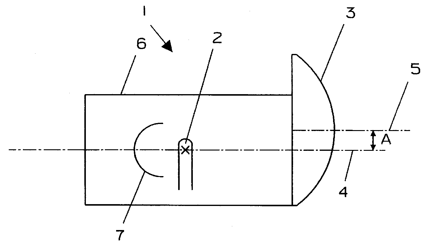
根据本发明,根据权利要求1的聚光灯完成这个任务。在本专利申请文本中的概念“前透镜的偏心安置”应理解为:前透镜如此安置,以使前透镜的主光轴与聚光灯的主光轴平行,但这两个光轴并不重合(见图1)。According to the invention, a spotlight according to claim 1 fulfills this task. The concept "eccentric arrangement of the front lens" in the text of this patent application should be understood as: the front lens is arranged so that the main optical axis of the front lens is parallel to the main optical axis of the spotlight, but the two optical axes do not coincide ( see picture 1).
根据本发明的聚光灯的优选实施例即是权利要求2至4中所涉及的对象。Preferred embodiments of the spotlight according to the invention are what are referred to in
根据本发明的聚光灯的一个显著优点是,将定向地产生的光分布的不对称性与聚光灯的可聚焦性结合起来,使得甚至单个聚光灯具有在各种场合下高度灵活使用的可能性。例如在前所提及的博物馆大画像换成小画像的例子中,根据本发明的聚光灯在画像更换的情况下却无须更换。只需聚焦在新的画面大小上,也即变动聚光灯的出射角度以适合新的画面大小即可。这样的聚光灯可停留在原来的空间位置,而无须用另外的聚光灯来替代。A significant advantage of the spotlight according to the invention is that the combination of the asymmetry of the directionally generated light distribution with the focusability of the spotlight enables a highly flexible use of even a single spotlight in various situations. For example, in the aforementioned example where a large portrait in a museum is replaced by a small portrait, the spotlight according to the present invention does not need to be replaced when the portrait is changed. Just focus on the new frame size, that is, change the beam angle of the spotlight to fit the new frame size. Such a spotlight can stay in the original spatial position without replacing it with another spotlight.
此外根据本发明的聚光灯提供了一种无级的、均匀的光强分布。由此充分利用可供使用的全部光强。我们也可以使用小功率的光源,使能量的损失减少至很小。在室内使用的情况下可以相应地减少热量。这是一个很大的优点,如果我们考虑到,在室内和摄影棚中至今仍然主要是使用白炽聚光灯,而这种灯可有效利用的光只是其所耗能量的约10%。Furthermore, the spotlight according to the invention provides a stepless, uniform light intensity distribution. In this way, all available light intensities are fully utilized. We can also use a low-power light source to minimize energy loss. In the case of indoor use, the heat can be reduced accordingly. This is a great advantage if we take into account that in the interior and in the studio until now predominantly incandescent spotlights are still used, which effectively use only about 10% of the energy they consume.
在很多摄影棚中仍然几乎完全使用定向灯光和白炽灯。按照现有的技术状况,在一个相对来说较小的摄影棚中灯光消耗的能量为40kW左右,在较大的摄影棚和某些照明场合下则需要几百kW。如果我们考虑到,空调所耗能量是灯光所耗的数倍,那么在一个使用40kW白炽灯的小摄影棚里就需要200kW的能量用于空调。如果使用根据本发明的聚光灯作为定向灯光,那么定向灯光所耗能量就能减至50%甚至更少。如果我们考虑到,在减少灯光所耗能量的同时也大幅度地减少了空调所耗的能量,这样能量消耗就能节约数倍。Directional lighting and incandescent lighting are still used almost exclusively in many studios. According to the existing technical situation, the energy consumption of light in a relatively small studio is about 40kW, and it needs hundreds of kW in larger studios and some lighting occasions. If we take into account that air conditioning consumes several times more energy than lighting, then a small studio with 40kW incandescent lamps would require 200kW of energy for air conditioning. If the spotlight according to the present invention is used as a directional light, the energy consumed by the directional light can be reduced to 50% or even less. If we consider that while reducing the energy consumed by the lights, the energy consumed by the air conditioner is also greatly reduced, so that the energy consumption can be saved several times.
在电影,电视,剧院和照相中所应用的可聚焦灯光一般来说照射面积较小,且通常用于一些不同的照射距离,由此而产生明显的阴影。因此这种照明方式一般都需要大面积的泛光灯具加以补充。在此领域中人们越来越多地使用装有荧光管的泛光灯具。然而在大部分情况下这种泛光灯具必须安置在离被照物体很近的距离内。因为摄影机是单眼工作的,所以摄影镜头只能或多或少地在二维平面上捕捉所摄对象。这样就失去了用双眼观察对象自然而产生的空间深度感觉。所以尽管新的趋势是应用软光和大面积布光,仍然不可能放弃背光,轮廓光,重点光的应用,这些光是或多或少地朝着摄影机方向投射的,它们的任务是,将被照射物体在大面积布光的情况下三维地展现出来。Focusable lights used in film, television, theatre, and photography typically illuminate a small area and are often used at a number of different illumination distances, resulting in significant shadows. Therefore, this lighting method generally needs to be supplemented by large-area floodlights. Floodlights with fluorescent tubes are increasingly being used in this field. However, in most cases such floodlights must be placed within a short distance from the object to be illuminated. Because the camera works with one eye, the photographic lens can only capture the subject more or less on a two-dimensional plane. This loses the sense of spatial depth that naturally arises from viewing objects with both eyes. So although the new trend is to apply soft light and large-area lighting, it is still impossible to give up the application of backlight, rim light, and accent light. These lights are more or less projected towards the camera. Their task is to The illuminated object is displayed three-dimensionally in the case of large-area lighting.
人们不能完全放弃这样一种照明方式,在这种照明方式下朝着摄影机方向投射的光线的强度常常是从摄影机方向出射的光线强度的两倍,这种定向光线在一般非常均匀的软光照明中仍然一直起着重要的作用。特别是,当所摄的物体在拍摄过程中是运动着的,基于本发明的可聚焦聚光灯的定向光线的非对称照明由于其平滑的光强分布和低能量消耗而具有显著的优点。One cannot completely abandon a lighting method in which the intensity of the light projected towards the camera is often twice that of the light emitted from the direction of the camera. still plays an important role. Especially, when the photographed object is moving during the photographing process, the asymmetric illumination based on the directional light of the focusable spotlight of the present invention has significant advantages due to its smooth light intensity distribution and low energy consumption.
作为定向灯光的可聚焦的聚光灯在大部分情况下安置在向下45°角俯视的位置上,同时我们也可以设定,在实践中定向灯光从来不会设置在摄影机的主轴上,而是同样以一定的角度,通常从侧面以45°角与摄影机主轴相交,如果这个相交角度变化,也可以通过前透镜的旋转加以补偿,如在本发明的实施例中根据权利要求2所叙。此外,角度的变化也可以根据本发明的聚光灯的实施例中的权利要求3,即借助偏心安置的前透镜的可移动性加以调整补偿。在根据本发明的聚光灯的实施例中,前透镜的主轴和聚光灯的主轴之间的垂直距离是可以变化的。Focusable spotlights as directional lights are in most cases positioned looking down at a 45° angle, but we can also set that in practice directional lights are never set on the main axis of the camera, but the same Intersecting the main axis of the camera at a certain angle, usually at an angle of 45° from the side, if this angle of intersection varies, it can also be compensated by the rotation of the front lens, as in an embodiment of the invention according to
附图说明Description of drawings
根据本发明的聚光灯的实施例将由下列附图加以说明。Embodiments of a spotlight according to the invention will be illustrated by the following figures.
图1为根据本发明的聚光灯的第一实施例的截面示意图。Fig. 1 is a schematic cross-sectional view of a first embodiment of a spotlight according to the present invention.
图2为图1所显示聚光灯的正面示意图。Fig. 2 is a schematic front view of the spotlight shown in Fig. 1 .
图3为根据本发明的第二实施例中一个前透镜的形状示意图。Fig. 3 is a schematic diagram of the shape of a front lens according to the second embodiment of the present invention.
图4为根据本发明的第三实施例中一个前透镜的形状示意图。Fig. 4 is a schematic diagram of the shape of a front lens according to a third embodiment of the present invention.
图5为根据本发明的第三实施例的正面示意图。Fig. 5 is a schematic front view of a third embodiment according to the present invention.
具体实施方式Detailed ways
在图1里根据本发明的聚光灯实施例1中,6为灯壳。在灯壳6中安装有灯泡2及适合灯泡2的反射器7。在图1中聚光灯1的主光轴由中心线4表示。In the spotlight embodiment 1 according to the present invention in FIG. 1 , 6 is a lamp housing. A
灯泡2及反射器7可在聚光灯内移动,从而聚光灯1的出射角可以变动。出射角的可变动性按现有技术状况是公知的,因而在此不再详细解释。The
在图1所示的根据本发明的聚光灯1的实施例中还有一个前透镜3。这个前透镜3是一个偏心安置的聚光镜,它的主光轴在图1中由中心线5表示。前透镜3的主光轴5与聚光灯1的主光轴4平行,然而不与之重合。聚光灯1的主光轴4与前透镜3的主光轴5之间的距离由符号A表示。In the embodiment of the spotlight 1 according to the invention shown in FIG. 1 there is also a
图2是图1中所示根据本发明的聚光灯的实施例1的正面示意图。为概略起见,在图2中前透镜3的主光轴5以及它与聚光灯1主光轴4之间的距离A未标示出来。Fig. 2 is a schematic front view of Embodiment 1 of the spotlight according to the present invention shown in Fig. 1 . For the sake of clarity, the main
如同图1,在图2中也可清楚地看到,这里所示意的根据本发明的聚光灯1的实施例中的前透镜3,其部分凸出聚光灯1的灯壳6之外。Like FIG. 1 , it can also be clearly seen in FIG. 2 that the
前透镜3是如此安装的,它可以围绕聚光灯的主光轴旋转。在图2中箭头表示旋转方向。然而前透镜3的主光轴5与聚光灯1的主光轴4的径向距离A在这个根据本发明的聚光灯的这个实施例中是保持不变的。The
图1所示意的实施例中的前透镜3是一个完全普通的对称聚光透镜。The
在根据本发明的另外一些实施例中使用另一类聚光透镜作为前透镜。例如在根据本发明的聚光灯的一个特别优选的实施例中使用这样一个聚光透镜作为前透镜,这个前透镜是如此形成的,它似乎是从一块更大的透镜以这样的方式切割而成,这个切割下来的可利用的部分在一个面上与原来的更大透镜的一个正常边缘相切。我们可以把这种前透镜想象成它是从一块大透镜按上述方式切割下来的一部分。Another type of condenser lens is used as the front lens in some other embodiments according to the present invention. For example, in a particularly preferred embodiment of the spotlight according to the invention, a condenser lens is used as the front lens, which is formed in such a way that it appears to be cut from a larger lens in such a way that The cut usable portion is tangent on one face to a normal edge of the original larger lens. We can think of this front lens as a part cut from a large lens in the manner described above.
为明了起见,图3显示了一个前透镜3′的实施例。此处符号8标示作为基体透镜或者作为“想象中的”基本透镜的普通对称聚光透镜。这个基体透镜8的主光轴9位于其中心。为说明根据本发明的不同实施例,在此处我们将聚光透镜3′作为聚光灯的前透镜,它是如此形成的,它似乎是从基体透镜8切割而成,这个切割下来的有用部分,也即图3中的前透镜3′在一个面上与基体透镜8的一个正常边缘相切。在这个前透镜3′的实施例中,主光轴9相对于前透镜圆周不再处于中心。为此,这个根据本发明的实施例的聚光灯有下列优点,图3中的前透镜3′,不象图1和图2中所显示的实施例中的前透镜3,它不必从侧面凸出聚光灯灯壳6以外一部分。For clarity, Figure 3 shows an embodiment of a front lens 3'. The
在图1至3中显示了具有这种前透镜3,3′的根据本发明的实施例中,前透镜3,3′都具有圆周边缘。然而也有根据本发明的聚光灯的其它实施例,其前透镜的边缘不是圆周形的。例如前透镜也可具有基本椭圆形的边缘。图4显示了这种前透镜的一个实施例,此处前透镜由符号3″所标示。这样一个前透镜3″的实施例也可回归到在图3中已公开的具有主光轴9的普通对称聚光透镜(基本透镜)8。图4中的前透镜3″从原则上来说也可以用与图3中的前透镜3′相似的方式从基体透镜,也即从普通的对称聚光透镜8,切割而成。仅是外周形状有所不同。In the embodiments according to the invention with such
最后图5显示了,图4中的前透镜3″是如何安装在聚光灯灯壳6上的,并由此导出根据本发明的聚光灯的另一个实施例。在图5中虽然聚光灯的主光轴没有明确标示出来,然而正如图1和图2一样,在这个实施例中它也是从由聚光灯灯壳6所构成空间的中心延伸出去的。图4和图5中的前透镜3″是可以围绕聚光灯的主光轴旋转的。图5中的弯曲箭头显示了这种可旋转性。此外前透镜3″还可以在与主光轴垂直的方向上来回移动。这种可移动性在图5中由直线双向箭头所显示。因此在这个根据本发明的聚光灯的实施例中前透镜3″的主光轴与聚光灯的主光轴之间的垂直距离是可以变化的。Finally Fig. 5 has shown, how the
虽然在前所提及的根据本发明的聚光灯的实施例中仅仅详细叙述了单透镜系统,但是本发明并不仅限于单透镜的可聚焦聚光灯。本发明还包括了双透镜甚至一般来说具有更多透镜的可聚焦聚光灯,在这样的聚光灯里,在前透镜和灯泡之间还安装有一个或者更多的透镜。对本发明来说最关键的是,前透镜在一个可聚焦聚光灯中的偏心安置。至于其他更多透镜的形状以及在聚光灯中的排列,对本发明来说不是关键的。Although only a single-lens system was described in detail in the above-mentioned embodiments of the spotlight according to the invention, the invention is not limited to single-lens focusable spotlights. The invention also includes focusable spotlights with double lenses and even more lenses in general, where one or more lenses are mounted between the front lens and the bulb. Crucial to the invention is the off-centre arrangement of the front lens in a focusable spotlight. As for the shape of the further lenses and their arrangement in the spotlight, it is not critical to the invention.
最后还要强调的是,本发明并不限于某种一定功率的聚光灯。例如根据本发明的聚光灯可以做成只有几十瓦用于细微画像照明的聚光灯,也可以做成具有几十千瓦的大功率聚光灯。Finally, it should be emphasized that the present invention is not limited to a spotlight of a certain power. For example, the spotlight according to the present invention can be made into a spotlight with only tens of watts for subtle portrait illumination, or a high-power spotlight with tens of kilowatts.
Claims (4)
Applications Claiming Priority (2)
| Application Number | Priority Date | Filing Date | Title |
|---|---|---|---|
| EP04014665.6 | 2004-06-23 | ||
| EP04014665.6A EP1610055B1 (en) | 2004-06-23 | 2004-06-23 | Focusable projector with asymmetrical light distribution |
Publications (1)
| Publication Number | Publication Date |
|---|---|
| CN1724924A true CN1724924A (en) | 2006-01-25 |
Family
ID=34925443
Family Applications (1)
| Application Number | Title | Priority Date | Filing Date |
|---|---|---|---|
| CNA2005100788398A Withdrawn CN1724924A (en) | 2004-06-23 | 2005-06-23 | Focusable spotlight with asymmetrical light distribution |
Country Status (3)
| Country | Link |
|---|---|
| US (1) | US7347588B2 (en) |
| EP (1) | EP1610055B1 (en) |
| CN (1) | CN1724924A (en) |
Cited By (1)
| Publication number | Priority date | Publication date | Assignee | Title |
|---|---|---|---|---|
| CN104676485A (en) * | 2015-03-26 | 2015-06-03 | 成都恒坤光电科技有限公司 | Light-distributing lens and equipment for discrete LED (light-emitting diode) light source |
Families Citing this family (4)
| Publication number | Priority date | Publication date | Assignee | Title |
|---|---|---|---|---|
| TWM364824U (en) * | 2008-09-19 | 2009-09-11 | Genius Electronic Optical Co Ltd | Optical lens body of bilateral asymmetry polarization illumination |
| DE102011082844A1 (en) * | 2011-09-16 | 2013-03-21 | Zumtobel Lighting Gmbh | Lighting arrangement, in particular for escape route lighting |
| US10060601B2 (en) * | 2014-02-04 | 2018-08-28 | Targetti Sankey S.P.A. | Lighting device |
| DE102015119106A1 (en) * | 2015-11-06 | 2017-05-11 | Siteco Beleuchtungstechnik Gmbh | Indoor or outdoor lamp, especially street lamp, with movable freeform lens |
Family Cites Families (10)
| Publication number | Priority date | Publication date | Assignee | Title |
|---|---|---|---|---|
| DE386071C (en) | 1922-12-01 | 1923-12-14 | Schwabe & Co | Lens spotlights |
| US2282167A (en) * | 1937-08-21 | 1942-05-05 | George M Cressaty | Flashlight |
| US2210554A (en) * | 1939-01-17 | 1940-08-06 | Charles L Beckman | Spotlight |
| US4823243A (en) | 1986-08-26 | 1989-04-18 | Dedotec Optronische Und Mechanische Systeme Gmbh | Miniature spotlight with extremely variable exit angle and constant even field of illumination |
| DE19625923A1 (en) * | 1996-06-28 | 1998-01-08 | Hella Kg Hueck & Co | Headlights for vehicles |
| EP0846913B1 (en) | 1996-12-04 | 2004-07-07 | Dedo Weigert Film GmbH | Spotlight with variable illumination output angle |
| EP0997684B1 (en) * | 1998-10-29 | 2005-03-30 | Arnold & Richter Cine Technik Gmbh & Co. Betriebs Kg | Headlamp |
| DE19901391A1 (en) | 1999-01-15 | 2000-09-14 | Weigert Dedo Film Gmbh | Headlights with variable beam angle and with aspherical front lens |
| FR2793001B1 (en) * | 1999-04-29 | 2001-09-14 | Valeo Vision | MOTOR VEHICLE PROJECTOR CAPABLE OF EMITTING A CROSSED BEAM AND A MODIFIED CROSSED BEAM FOR HIGHWAY TRAFFIC |
| DE10063134A1 (en) | 2000-12-18 | 2002-06-27 | Weigert Dedo Film Gmbh | Focusable headlight with negative lens |
-
2004
- 2004-06-23 EP EP04014665.6A patent/EP1610055B1/en not_active Expired - Lifetime
-
2005
- 2005-06-23 US US11/159,136 patent/US7347588B2/en not_active Expired - Fee Related
- 2005-06-23 CN CNA2005100788398A patent/CN1724924A/en not_active Withdrawn
Cited By (2)
| Publication number | Priority date | Publication date | Assignee | Title |
|---|---|---|---|---|
| CN104676485A (en) * | 2015-03-26 | 2015-06-03 | 成都恒坤光电科技有限公司 | Light-distributing lens and equipment for discrete LED (light-emitting diode) light source |
| CN104676485B (en) * | 2015-03-26 | 2017-07-04 | 成都恒坤光电科技有限公司 | A kind of light-distribution lens and equipment for discrete LED sources |
Also Published As
| Publication number | Publication date |
|---|---|
| US7347588B2 (en) | 2008-03-25 |
| EP1610055B1 (en) | 2016-08-17 |
| US20050286249A1 (en) | 2005-12-29 |
| EP1610055A1 (en) | 2005-12-28 |
Similar Documents
| Publication | Publication Date | Title |
|---|---|---|
| CN1113183C (en) | High efficiency, highly controllable lighting apparatus and method | |
| CN105431680B (en) | For the independent device, method and system aimed at and interdict step in illumination target region | |
| RU2079044C1 (en) | Lighting system for optical elements, projectors and photographic enlarger | |
| US6062710A (en) | Light fixture with at least one lens or reflector as image magnifier and a diffuser for reducing glare | |
| US20040085770A1 (en) | Luminaire | |
| WO2025228290A1 (en) | Lamp | |
| CN1724924A (en) | Focusable spotlight with asymmetrical light distribution | |
| CN107567567B (en) | Solid state lighting device and luminaire | |
| JP5444484B1 (en) | LED lighting device | |
| JP2009058924A (en) | Lighting system | |
| CA2526865C (en) | Four segment reflector | |
| CA2676894A1 (en) | Asymmetric lighting systems and applications thereof | |
| JP6178796B2 (en) | LIGHTING DEVICE AND ROAD LIGHTING EQUIPMENT HAVING THE LIGHTING DEVICE | |
| CN113296331B (en) | A kind of LED automatic electric focus photography spotlight and its method | |
| CN2620814Y (en) | Lighting lamps and lanterns with front reflector | |
| CN1251663A (en) | Lighting device for projector | |
| CN224203556U (en) | An angle-adjustable arched light source and machine vision inspection device | |
| CN104913246A (en) | Anti-dazzling project lamp | |
| CN222068324U (en) | A birefringent optical lens | |
| TW201943998A (en) | Spotlight device | |
| CN213146290U (en) | A Tightly Connected Flood Light | |
| CN108826084A (en) | Variable-focus projection lamp device | |
| CN1847975A (en) | light source unit for projector | |
| CN211600586U (en) | Lampshades and lighting fixtures | |
| TWI298378B (en) | Lamps for vehicles |
Legal Events
| Date | Code | Title | Description |
|---|---|---|---|
| C06 | Publication | ||
| PB01 | Publication | ||
| C10 | Entry into substantive examination | ||
| SE01 | Entry into force of request for substantive examination | ||
| C04 | Withdrawal of patent application after publication (patent law 2001) | ||
| WW01 | Invention patent application withdrawn after publication |