CN1737726A - Portable computer - Google Patents
Portable computer Download PDFInfo
- Publication number
- CN1737726A CN1737726A CNA2005100905315A CN200510090531A CN1737726A CN 1737726 A CN1737726 A CN 1737726A CN A2005100905315 A CNA2005100905315 A CN A2005100905315A CN 200510090531 A CN200510090531 A CN 200510090531A CN 1737726 A CN1737726 A CN 1737726A
- Authority
- CN
- China
- Prior art keywords
- connector
- portable computer
- input block
- block body
- hinge
- Prior art date
- Legal status (The legal status is an assumption and is not a legal conclusion. Google has not performed a legal analysis and makes no representation as to the accuracy of the status listed.)
- Granted
Links
Images


Classifications
-
- E—FIXED CONSTRUCTIONS
- E05—LOCKS; KEYS; WINDOW OR DOOR FITTINGS; SAFES
- E05B—LOCKS; ACCESSORIES THEREFOR; HANDCUFFS
- E05B65/00—Locks or fastenings for special use
- E05B65/006—Locks or fastenings for special use for covers or panels
-
- G—PHYSICS
- G06—COMPUTING OR CALCULATING; COUNTING
- G06F—ELECTRIC DIGITAL DATA PROCESSING
- G06F1/00—Details not covered by groups G06F3/00 - G06F13/00 and G06F21/00
- G06F1/16—Constructional details or arrangements
- G06F1/1613—Constructional details or arrangements for portable computers
-
- G—PHYSICS
- G06—COMPUTING OR CALCULATING; COUNTING
- G06F—ELECTRIC DIGITAL DATA PROCESSING
- G06F1/00—Details not covered by groups G06F3/00 - G06F13/00 and G06F21/00
- G06F1/16—Constructional details or arrangements
- G06F1/1613—Constructional details or arrangements for portable computers
- G06F1/1615—Constructional details or arrangements for portable computers with several enclosures having relative motions, each enclosure supporting at least one I/O or computing function
- G06F1/1616—Constructional details or arrangements for portable computers with several enclosures having relative motions, each enclosure supporting at least one I/O or computing function with folding flat displays, e.g. laptop computers or notebooks having a clamshell configuration, with body parts pivoting to an open position around an axis parallel to the plane they define in closed position
- G06F1/162—Constructional details or arrangements for portable computers with several enclosures having relative motions, each enclosure supporting at least one I/O or computing function with folding flat displays, e.g. laptop computers or notebooks having a clamshell configuration, with body parts pivoting to an open position around an axis parallel to the plane they define in closed position changing, e.g. reversing, the face orientation of the screen with a two degrees of freedom mechanism, e.g. for folding into tablet PC like position or orienting towards the direction opposite to the user to show to a second user
-
- G—PHYSICS
- G06—COMPUTING OR CALCULATING; COUNTING
- G06F—ELECTRIC DIGITAL DATA PROCESSING
- G06F1/00—Details not covered by groups G06F3/00 - G06F13/00 and G06F21/00
- G06F1/16—Constructional details or arrangements
- G06F1/1613—Constructional details or arrangements for portable computers
- G06F1/1633—Constructional details or arrangements of portable computers not specific to the type of enclosures covered by groups G06F1/1615 - G06F1/1626
- G06F1/1637—Details related to the display arrangement, including those related to the mounting of the display in the housing
- G06F1/1654—Details related to the display arrangement, including those related to the mounting of the display in the housing the display being detachable, e.g. for remote use
-
- G—PHYSICS
- G06—COMPUTING OR CALCULATING; COUNTING
- G06F—ELECTRIC DIGITAL DATA PROCESSING
- G06F1/00—Details not covered by groups G06F3/00 - G06F13/00 and G06F21/00
- G06F1/16—Constructional details or arrangements
- G06F1/1613—Constructional details or arrangements for portable computers
- G06F1/1633—Constructional details or arrangements of portable computers not specific to the type of enclosures covered by groups G06F1/1615 - G06F1/1626
- G06F1/1656—Details related to functional adaptations of the enclosure, e.g. to provide protection against EMI, shock, water, or to host detachable peripherals like a mouse or removable expansions units like PCMCIA cards, or to provide access to internal components for maintenance or to removable storage supports like CDs or DVDs, or to mechanically mount accessories
-
- G—PHYSICS
- G06—COMPUTING OR CALCULATING; COUNTING
- G06F—ELECTRIC DIGITAL DATA PROCESSING
- G06F1/00—Details not covered by groups G06F3/00 - G06F13/00 and G06F21/00
- G06F1/16—Constructional details or arrangements
- G06F1/1613—Constructional details or arrangements for portable computers
- G06F1/1633—Constructional details or arrangements of portable computers not specific to the type of enclosures covered by groups G06F1/1615 - G06F1/1626
- G06F1/1675—Miscellaneous details related to the relative movement between the different enclosures or enclosure parts
- G06F1/1679—Miscellaneous details related to the relative movement between the different enclosures or enclosure parts for locking or maintaining the movable parts of the enclosure in a fixed position, e.g. latching mechanism at the edge of the display in a laptop or for the screen protective cover of a PDA
-
- G—PHYSICS
- G06—COMPUTING OR CALCULATING; COUNTING
- G06F—ELECTRIC DIGITAL DATA PROCESSING
- G06F1/00—Details not covered by groups G06F3/00 - G06F13/00 and G06F21/00
- G06F1/16—Constructional details or arrangements
- G06F1/1613—Constructional details or arrangements for portable computers
- G06F1/1633—Constructional details or arrangements of portable computers not specific to the type of enclosures covered by groups G06F1/1615 - G06F1/1626
- G06F1/1675—Miscellaneous details related to the relative movement between the different enclosures or enclosure parts
- G06F1/1681—Details related solely to hinges
-
- Y—GENERAL TAGGING OF NEW TECHNOLOGICAL DEVELOPMENTS; GENERAL TAGGING OF CROSS-SECTIONAL TECHNOLOGIES SPANNING OVER SEVERAL SECTIONS OF THE IPC; TECHNICAL SUBJECTS COVERED BY FORMER USPC CROSS-REFERENCE ART COLLECTIONS [XRACs] AND DIGESTS
- Y10—TECHNICAL SUBJECTS COVERED BY FORMER USPC
- Y10S—TECHNICAL SUBJECTS COVERED BY FORMER USPC CROSS-REFERENCE ART COLLECTIONS [XRACs] AND DIGESTS
- Y10S248/00—Supports
- Y10S248/917—Video display screen support
- Y10S248/919—Adjustably orientable video screen support
- Y10S248/92—Angular and linear video display screen support adjustment
Landscapes
- Engineering & Computer Science (AREA)
- Computer Hardware Design (AREA)
- Theoretical Computer Science (AREA)
- Physics & Mathematics (AREA)
- General Engineering & Computer Science (AREA)
- Human Computer Interaction (AREA)
- General Physics & Mathematics (AREA)
- Mathematical Physics (AREA)
- Casings For Electric Apparatus (AREA)
- User Interface Of Digital Computer (AREA)
Abstract
本发明涉及一种便携式计算机,包括:平板体,用于容纳多个硬件元件并且能够进行平板操作;输入单元体,用于将数据输入到平板体;一个连接物,其第一端可旋转地结合到平板体的后部,其第二端可旋转地结合到输入单元体的后部,平板体在平板操作位置和暴露位置之间转换,在平板操作位置,平板体被折叠到输入单元体之上,同时连接物介于平板体的后部和输入单元体的上表面之间,在暴露位置,与连接物结合的平板体与输入单元体分离开,并且输入单元体被暴露出来。因此,本发明提供这样一种便携式计算机,它使用户能够旋转平板体,并且其具有吸引人的和纤小的外观。

The invention relates to a portable computer, comprising: a tablet body for accommodating a plurality of hardware components and capable of tablet operation; an input unit body for inputting data into the tablet body; a connector whose first end is rotatable Coupled to the rear of the tablet body, the second end of which is rotatably coupled to the rear of the input unit body, the tablet body transitions between a tablet operating position and an exposed position, in which the tablet body is folded into the input unit body Above, while the connector is interposed between the rear portion of the plate body and the upper surface of the input unit body, at the exposed position, the plate body combined with the connector is separated from the input unit body, and the input unit body is exposed. Accordingly, the present invention provides a portable computer that enables the user to rotate the tablet and that has an attractive and slim appearance.
Description
本申请要求于2004年8月17日提交到韩国知识产权局的韩国专利申请第2004-0064850号的利益,该申请的内容公开于此,以资参考。This application claims the benefit of Korean Patent Application No. 2004-0064850 filed with the Korean Intellectual Property Office on Aug. 17, 2004, the contents of which are hereby disclosed by reference.
技术领域Technical field
本发明总的来说涉及一种便携式计算机。更清楚地说,本发明的实施例涉及一种能够进行平板操作的便携式计算机。The present invention generally relates to a portable computer. More specifically, embodiments of the present invention relate to a portable computer capable of tablet operation.
背景技术 Background technique
通常,便携式计算机当被携带时需要好的移动性和方便的操作等等。这里,术语便携式计算机指任何容易携带的计算机,如膝上型计算机、笔记本型计算机、掌上型计算机等。Generally, a portable computer requires good mobility, convenient operation, and the like when being carried. Here, the term portable computer refers to any computer that is easily carried around, such as a laptop computer, notebook computer, palmtop computer, and the like.
例如,在U.S.专利第6,005,767号公开的一种便携式计算机包括:计算机主体,具有多个硬件元件;显示体,接收视频信号和基于视频信号显示图像。另外,显示体通过第一铰链和第二铰链折叠到计算机主体上和从计算机主体打开。另外,在计算机主体的内部包括具有中央处理单元的主板、图形处理芯片等等,并且在其外部包括输入单元,如键盘、鼠标等等。For example, a portable computer disclosed in U.S. Patent No. 6,005,767 includes: a computer main body having a plurality of hardware components; and a display body receiving a video signal and displaying an image based on the video signal. In addition, the display body is folded onto and unfolded from the computer body by the first hinge and the second hinge. In addition, a main board having a central processing unit, a graphics processing chip, etc. are included inside the computer main body, and input units such as a keyboard, a mouse, etc. are included outside it.
具有这种构造,传统的便携式计算机显示体可被调节为从计算机主体不仅打开相对于0°的90°的角度,而且打开相对于0°的180°的角度,其中0°指显示体完全折叠到计算机主体上。With this configuration, a conventional portable computer display can be adjusted to open not only an angle of 90° from the main body of the computer, but also an angle of 180° relative to 0°, where 0° means the display is fully folded onto the computer body.
在显示体具有触摸屏功能和允许用户执行平板操作的情况下,显示器不得不反复地在0°到180°之间旋转。因此,需要可平滑地和精密地旋转的显示体以提供方便的操作。In the case where the display body has a touch screen function and allows the user to perform tablet operations, the display has to be repeatedly rotated between 0° and 180°. Therefore, there is a need for a display body that can be rotated smoothly and precisely to provide convenient operation.
另外,用户倾向于想要吸引人和纤小的设计。因此,便携式计算机最好具有吸引人的和纤小的外观从而满足用户的需要。Additionally, users tend to want attractive and slim designs. Therefore, it is desirable for the portable computer to have an attractive and slim appearance so as to satisfy the user's needs.
发明内容Contents of the invention
因此,本发明的一方面在于提供一种便携式计算机,其中,方便于用户旋转平板体,并且具有吸引人的纤小的外观。Accordingly, an aspect of the present invention is to provide a portable computer in which it is convenient for a user to rotate a tablet body and has an attractive slim appearance.
本发明的上述和/或其他方面可通过提供这样一种便携式计算机来实现,该便携式计算机包括:平板体,用于容纳多个硬件元件并且能够进行平板操作;输入单元体,用于将数据输入到平板体;一个连接物,其第一端可旋转地结合到平板体的后部,其第二端可旋转地结合到输入单元体的后部。其中,平板体可在平板操作位置和暴露位置之间转换,在平板操作位置,平板体被折叠到输入单元体之上,同时连接物介于平板体的后部和输入单元体的上表面之间,在暴露位置,与连接物结合的平板体与输入单元体分离开,并且输入单元体的上表面被暴露到外面。The above and/or other aspects of the present invention can be achieved by providing a portable computer comprising: a tablet body for accommodating a plurality of hardware components and capable of tablet operation; an input unit body for inputting data to the plate body; a connector whose first end is rotatably coupled to the rear of the plate body and whose second end is rotatably coupled to the rear of the input unit body. Wherein, the flat body can be converted between the flat operating position and the exposed position, and in the flat operating position, the flat body is folded onto the input unit body, and the connector is interposed between the rear part of the flat body and the upper surface of the input unit body Meanwhile, at the exposed position, the plate body combined with the connector is separated from the input unit body, and the upper surface of the input unit body is exposed to the outside.
根据本发明的另一方面,平板体可以可拆卸地结合到输入单元体上。According to another aspect of the present invention, the plate body may be detachably coupled to the input unit body.
根据本发明的另一方面,便携式计算机还可包括:结合单元,该结合单元被设置在连接物和平板主体之间的结合部分中,并且可拆卸地将平板体结合到输入单元体上,其中,结合单元包括设置在平板体和连接物的其中一个中的突起和可旋转地设置在另一个中的旋转板,该旋转板形成有可锁到所述突起上的旋转突起。According to another aspect of the present invention, the portable computer may further include: a combination unit provided in a combination part between the connector and the tablet main body, and detachably combines the tablet body to the input unit body, wherein The coupling unit includes a protrusion provided in one of the plate body and the link and a rotating plate rotatably provided in the other, the rotating plate being formed with a rotating protrusion lockable to the protrusion.
根据本发明的另一方面,便携式计算机还可包括:设置为在输入单元体内滑动的插销,该插销与旋转板互锁,并且旋转旋转板以使旋转突起锁到所述突起上和从所述突起释放。According to another aspect of the present invention, the portable computer may further include: a latch arranged to slide in the input unit body, the latch interlocks with the rotating plate, and rotates the rotating plate to lock the rotating protrusion onto and from the protrusion. protrusion release.
根据本发明的另一方面,所述旋转板可形成有旋转导向突起,连接物形成有其中插入旋转导向突起的突起导向延长孔,插销形成有旋转导向延长孔,在平板操作位置,插入突起导向延长孔的旋转导向突起在旋转导向延长孔中被导向。According to another aspect of the present invention, the rotating plate may be formed with a rotation guide protrusion, the connector is formed with a protrusion guide elongated hole into which the rotation guide protrusion is inserted, and the latch is formed with a rotation guide elongated hole. The rotation guide protrusion of the elongated hole is guided in the rotation guide elongated hole.
根据本发明的另一方面,所述便携式计算机还可包括:杠杆,可旋转地设置在输入单元体上,与插销连接,并且允许插销在输入单元体中滑动。According to another aspect of the present invention, the portable computer may further include: a lever rotatably disposed on the input unit body, connected with the plug, and allowing the plug to slide in the input unit body.
根据本发明的另一方面,插销可形成杠杆突起,该杠杆包括:暴露到输入单元体外侧的柄;从所述柄延伸并且由在输入单元体中的杠杆突起制动的杠杆导向件。According to another aspect of the present invention, the latch may form a lever protrusion including: a shank exposed to the outside of the input unit body; and a lever guide extended from the shank and stopped by the lever protrusion in the input unit body.
根据本发明的另一方面,所述便携式计算机还可包括:导向件,设置在输入单元体内,并用于引导插销移动;制动器组件,将导向件与插销连接。According to another aspect of the present invention, the portable computer may further include: a guide member disposed in the input unit body for guiding the movement of the plug; and a stopper assembly connecting the guide member with the plug.
根据本发明的另一方面,所述便携式计算机还可包括:第一弹簧,其第一端结合到输入单元体上,其第二端结合到所述插销上,并且将弹性力施加到所述插销上。According to another aspect of the present invention, the portable computer may further include: a first spring, the first end of which is coupled to the input unit body, the second end of which is coupled to the latch, and applies elastic force to the on the latch.
根据本发明的另一方面,所述便携式计算机还可包括:锁定单元,设置在连接物和输入单元体之间,并且允许连接物锁到输入单元体上和从输入单元体释放。According to another aspect of the present invention, the portable computer may further include: a locking unit disposed between the connector and the input unit body and allowing the connector to be locked to and released from the input unit body.
根据本发明的另一方面,所述锁定单元可包括:锁定孔,设置在连接物和输入单元体的一个中;锁,设置为在另一个中滑动,并且包括钩子以锁到锁定孔中。According to another aspect of the present invention, the locking unit may include: a locking hole provided in one of the connector and the input unit body; and a lock provided to slide in the other and including a hook to be locked into the locking hole.
根据本发明的另一方面,所述便携式计算机还可包括:把手,设置为在输入单元体中滑动,连接到所述锁并且使所述锁滑动。According to another aspect of the present invention, the portable computer may further include: a handle configured to slide in the input unit body, connected to the lock and sliding the lock.
根据本发明的另一方面,所述便携式计算机还可包括:第一铰链,可旋转地将连接物和输入单元体相连;第二铰链,在与第一铰链隔开的位置上可旋转地将连接物和平板体相连。According to another aspect of the present invention, the portable computer may further include: a first hinge that rotatably connects the connector with the input unit body; a second hinge that rotatably connects the input unit body at a position spaced from the first hinge. The linker is connected to the plate body.
根据本发明的另一方面,所述便携式计算机还可包括:支撑单元,通过第二铰链可旋转地结合到连接物,其中,支撑单元形成有锁定孔,在平板操作位置,钩子被锁到该锁定孔中。According to another aspect of the present invention, the portable computer may further include: a support unit rotatably coupled to the connector through a second hinge, wherein the support unit is formed with a locking hole, and the hook is locked to the support unit in the tablet operating position. lock hole.
根据本发明的另一方面,所述第一铰链可包括:一对第一铰链轴;第一连接轴支撑器,被设置在连接物中并且用于支撑每个第一铰链轴的第一侧;第一主轴支撑器,被设置在输入单元体中并且用于支撑每个第一铰链轴的第二侧,每个第一铰链轴包括可旋转地互相结合的第一主铰链轴和第一连接铰链轴。According to another aspect of the present invention, the first hinge may include: a pair of first hinge shafts; a first connecting shaft supporter disposed in the joint and used to support the first side of each first hinge shaft a first main shaft supporter disposed in the input unit body and used to support the second side of each first hinge shaft, each first hinge shaft comprising a first main hinge shaft and a first main shaft rotatably coupled to each other; Connect the hinge shaft.
根据本发明的另一方面,所述第二铰链可包括:一对第二铰链轴;第二连接轴支撑器,被设置在连接物中并且用于支撑每个第二铰链轴的第一侧;第二主轴支撑器,被设置在支撑单元中并且用于支撑每个第二铰链轴的第二侧,每个第二铰链轴包括可旋转地互相结合的第二主铰链轴和第二连接铰链轴。According to another aspect of the present invention, the second hinge may include: a pair of second hinge shafts; a second connection shaft supporter disposed in the joint and used to support the first side of each second hinge shaft a second main shaft supporter, disposed in the support unit and used to support the second side of each second hinge shaft, each second hinge shaft comprising a second main hinge shaft and a second link rotatably coupled to each other Hinge axis.
根据本发明的另一方面,所述输入单元体可包括:连接物容纳部分,用于在平板操作位置容纳连接物。According to another aspect of the present invention, the input unit body may include: a connector accommodating part for accommodating the connector at the tablet operating position.
根据本发明的另一方面,所述连接物可包括:连接器组件,电连接平板体和输入单元体。According to another aspect of the present invention, the connecting object may include: a connector assembly electrically connecting the plate body and the input unit body.
根据本发明的另一方面,所述便携式计算机还可包括:第二弹簧,其第一端结合到输入单元体,其第二端结合到锁,并且将弹性力施加到锁。According to another aspect of the present invention, the portable computer may further include: a second spring having a first end coupled to the input unit body and a second end coupled to the lock, and applying an elastic force to the lock.
根据本发明的另一方面,所述便携式计算机还可包括:锁定单元,被设置在连接物和输入单元体之间,并且允许连接物锁到输入单元体上和从输入单元体释放开。According to another aspect of the present invention, the portable computer may further include: a locking unit disposed between the connector and the input unit body and allowing the connector to be locked to and released from the input unit body.
根据本发明的另一方面,所述锁定单元可包括:锁定孔,设置在连接物和输入单元体的一个中;锁,设置为在另一个中以滑动并且具有钩子以锁到锁定孔中。According to another aspect of the present invention, the locking unit may include: a locking hole provided in one of the connector and the input unit body; and a lock provided in the other to slide and having a hook to lock into the locking hole.
本发明的另外方面和/或优点一部分将在以下描述中被阐述,一部分,将从该描述中变得清楚,或者可通过本发明的实施学习到。Additional aspects and/or advantages of the invention will be set forth in the description which follows and, in part, will be apparent from the description, or may be learned by practice of the invention.
附图说明Description of drawings
通过下面结合附图对实施例进行的描述,本发明的上述和其他目的和优点将会变得更加清楚和更加容易理解,其中:The above and other objects and advantages of the present invention will become clearer and easier to understand through the following description of the embodiments in conjunction with the accompanying drawings, wherein:
图1是根据本发明实施例的便携式计算机在平板操作位置的透视图;1 is a perspective view of a portable computer in a tablet operating position according to an embodiment of the present invention;
图2是图1中的便携式计算机在分离的位置的透视图;Figure 2 is a perspective view of the portable computer of Figure 1 in a detached position;
图3是表示根据本发明实施例的旋转板结合到平板体的后部的示意性后视图;3 is a schematic rear view showing a rotating plate coupled to the rear of a plate body according to an embodiment of the present invention;
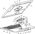
图4是根据本发明实施例的便携式计算机的分解透视图;4 is an exploded perspective view of a portable computer according to an embodiment of the present invention;
图5是图4中显示的插销、杠杆、导向件、制动组件、锁、钩和操作把手的放大的视图;Figure 5 is an enlarged view of the latch, lever, guide, brake assembly, lock, hook and operating handle shown in Figure 4;
图6是图4中的铰链组件的分解透视图;Figure 6 is an exploded perspective view of the hinge assembly in Figure 4;
图7是根据本发明实施例的便携式计算机的后透视图,其中,平板体从铰链组件分离;7 is a rear perspective view of a portable computer according to an embodiment of the present invention, wherein the tablet is separated from the hinge assembly;
图8和图9表示根据本发明实施例的在锁定单元和结合单元之间的操作;8 and 9 represent operations between the locking unit and the combining unit according to an embodiment of the present invention;
图10到图13表示根据本发明实施例的平板体的旋转状态。10 to 13 show the rotation state of the flat body according to the embodiment of the present invention.
具体实施方式 Detailed ways
现在,将详细说明本发明的实施例,其例子表示在附图中,其中,相同附图标记始终指代相同部件。以下,通过参照附图描述实施例以解释本发明。Embodiments of the present invention will now be described in detail, examples of which are illustrated in the accompanying drawings, wherein like reference numerals refer to like parts throughout. The embodiments are described below in order to explain the present invention by referring to the figures.
如图1和图2所示,根据本发明实施例的便携式计算机包括:平板体10,包括多个硬件元件并且能够进行平板操作;输入单元体20,可拆卸地连接到平板体10并且允许平板体10沿着图2中的“A”向从其分离;铰链组件120,被设置在平板主体10和输入单元体20之间。As shown in FIGS. 1 and 2, a portable computer according to an embodiment of the present invention includes: a
平板主体10包括:外壳12,用于形成外观;多个硬件元件(未示出),容纳在外壳12中且包括主板、中央处理单元(CPU)、随机存储器(RAM)等等;显示部分11,由外壳12支撑并且用于显示图像。The tablet
如图3所示,在外壳12的后部设置有:凹陷部分15,从外壳12的表面凹陷;一对突起13,从凹陷部分15的表面突出;一对导向槽14,从凹陷部分15的表面凹陷;连接部件16,设置在一对导向槽14之间。As shown in Figure 3, be provided with at the rear portion of shell 12: recessed
突起13允许旋转板130的旋转突起131锁在该处或者从该处释放。因此,如图3所示,在旋转突起131锁到突起13的同时,平板体10保持与输入单元体20的结合而不从输入单元体20分离。The
如图4所示,输入单元体20包括:上壳21,用于形成外观;下壳30,与上壳21的下部结合。As shown in FIG. 4 , the
上壳21设置有:键盘26,用于输入操作;连接物容纳部分24,从上壳21的上表面凹陷;穿透部分25,穿透地形成在所述上表面上;钩插入部分27,与穿透孔25相连,并且钩子100(在之后描述)穿过插入其。另外,上壳21与位于连接物容纳部分24的后部的一对铰链轴帽5结合;电缆帽3位于一对铰链轴帽5之间。The upper case 21 is provided with: a
另外,上壳21包括:一对结合部分23,一对铰链轴帽5结合到其上;安装槽22,电缆帽3被安装到其中。铰链轴帽5和结合部分23结合以将第一主铰链轴164a置于其间,从而第一主铰链轴164a被铰链轴帽5和结合部分23支撑。安装到安装槽22的电缆帽3由形成在下壳30中的电缆帽支撑件38支撑。In addition, the upper case 21 includes: a pair of coupling portions 23 to which a pair of hinge shaft caps 5 are coupled; and a mounting groove 22 into which the
如图4和图5所示,在上壳21和下壳30之间设置有:结合单元,可拆卸地将平板体10和输入单元体20结合;锁定单元,允许铰链组件120的连接物126(图7)锁定到输入单元体20上和从输入单元体20释放。As shown in FIGS. 4 and 5 , between the upper shell 21 and the
结合单元包括:突起13,形成在平板体10上;旋转突起131,形成在旋转板130中并且被锁定到突起13上;插销40,被设置在下壳30中并且直线地滑动以旋转旋转板130;杠杆60,使插销40在下壳30中滑动。另外,杠杆60弹性地与第四弹簧32结合以使杠杆60回复到它原来的位置。The coupling unit includes: a
如图4中所示,插销40被设置在下壳30中并且沿着直线方向滑动。这里,插销40与用于引导旋转板130和插销40的导向件70结合以沿着直线方向滑动,杠杆60使插销40滑动。另外,在插销40和导向件70之间设置有制动组件80、84。As shown in FIG. 4 , the
插销40位于形成在下壳30中的一对插销导向肋37上,并且通过第一弹簧43连接到下壳30,第一弹簧43沿着与插销40的滑动操作相反的方向施加弹性力。The
如图5所示,插销40包括:穿透地形成在其上的导向延长孔41;弹簧固定件42,用于固定第一弹簧43;杠杆突起45,与杠杆60结合;制动结合部分46,制动组件80、84与之结合;旋转导向延长孔44,与旋转板130结合。As shown in FIG. 5 , the
在导向延长孔41中插入从下壳30突起的插销凸起34(参照图4)。另外,弹簧固定件42与第一弹簧43的第二端结合,第一弹簧43的第一端固定到下壳30上。The latch protrusion 34 protruding from the
制动结合部分46与第二螺杆47结合,从而将制动组件80、84固定到插销40上。The
导向件70通过制动组件80、84与插销40连接,从而引导插销40以使其沿着直线方向滑动。The
如图5所示,导向件70形成有:导向凸起孔71,与形成在下壳30上的导向凸起33结合;第一到第三部件72、73和74,对应于插销40的滑动操作,用于容纳制动组件80、84(在之后描述)的制动突起82。As shown in FIG. 5, the
另外,如图5所示,制动组件80、84包括:制动器80,与插销40和导向件70相连;第三弹簧84,结合到制动器80上。In addition, as shown in FIG. 5 , the
制动器80形成有:制动通孔81,允许第二螺杆47穿过其中并且与插销40的制动结合部分46结合;制动突起82,对应于插销40的滑动操作,沿着导向件70的第一到第三部件72、73和74移动;The
第三弹簧84位于制动器80上并且弹性地将制动器80向下压。第三弹簧84具有:第一端,形成有第三弹簧孔85,并且通过穿过第三弹簧孔85的第二螺杆47结合到制动器80上;第二端,位于制动器80的突起83上。A
如图5所示,杠杆60包括:柄61,允许用户推动杠杆60;杠杆导向件62,从柄61延伸并且由插销40的杠杆突起45止动;杠杆结合孔63,形成在柄61和杠杆导向件62之间。As shown in Figure 5, the
柄61暴露在下壳30的外部,杠杆导向件62由插销40的杠杆突起45止动并且将杠杆60与插销40进行互锁。The
因此,形成在下壳30上的杠杆凸起31可旋转地插入到杠杆结合孔63中,从而杠杆60通过杠杆结合孔63和插入杠杆结合孔63中的杠杆凸起31被下壳30可旋转地支撑。Therefore, the lever protrusion 31 formed on the
锁定单元包括:锁定孔174,形成在固定件170(在之后讨论)中;锁90,被设置在插销40上并且具有钩子100以被锁到锁定孔174中;把手110,用于控制锁90移动。The locking unit includes: a locking
锁90从下壳30中的插销40分离并且位于所述插销40上,从而横向滑动到插销40的滑动方向上。The
锁90具有通过第二弹簧95连接到下壳30的第一端,其中,第二弹簧95施加与锁90的滑动方向相反的方向的弹性力。The
如图5所示,锁90包括:多个锁导向延长孔91,其中,多个下壳30的锁凸起35被插入;钩子100,将被锁到锁定孔174中;把手结合孔93,与把手110结合;第二弹簧固定件94,与第二弹簧95的第二端结合,第二弹簧95的第一端与下壳30结合。As shown in FIG. 5 , the
参照图4和图5,钩子100通过第三螺杆102结合到锁90上,并且钩子100包括:钩子部分103,根据锁90的滑动操作锁到固定器170(在之后讨论)的锁定部分174上或者从所述锁定部分174释放开;第三螺杆通孔101,穿透地形成在其上。因此,第三螺杆102穿过第三螺杆通孔101,然后与形成在锁90上的钩结合孔92结合。Referring to FIGS. 4 and 5, the
如图5所示,把手110包括:把手结合突起111,插入锁90的把手结合孔93中;把手部分112,暴露在下壳30的外部,允许用户推动把手110。As shown in FIG. 5 , the
如图6所示,铰链组件120包括:连接物,用于将平板体10和输入单元体20连接起来;第一铰链,可旋转地将连接物126与输入单元体20连接起来;第二铰链,在与第一铰链相隔的位置可旋转地将连接物126与平板体10连接起来;支撑单元,可旋转地结合到第二铰链和连接物126之间的结合部分上;旋转板130,可旋转地结合到支撑单元;连接器组件150,结合到支撑单元。As shown in Figure 6, the
连接物126的第一端通过第一铰链与输入单元体20相连,其第二端通过第二铰链与支撑单元相连。A first end of the
如图6中所示,连接物126包括上盖121和下盖160。上盖121包括:一对弯曲部分122,从上盖121的表面向上延伸;突起导向延长孔125,穿透地形成在所述表面上;上连接器安装部分123,通过切割与弯曲部分122相对的表面而形成,用于支撑连接器组件150的上部。As shown in FIG. 6 , the
上盖结合孔124形成在上盖121上,以在上连接器安装部分123的相对侧与下盖160结合。An upper
下盖160包括:下盖凸起161,对应上盖的弯曲部分122形成;下连接器安装部分162,对应上连接器安装部分123形成;延伸部分163,位于关于下连接器安装部分162的相对侧。The
支撑单元包括:支撑板140,介于连接物126和旋转板130之间;一对固定件170,分别结合在支撑板140的相对端部。The supporting unit includes: a supporting
支撑板140形成有:连接器插入孔141,穿透支撑板140的中部;多个旋转导向孔142,与连接器插入孔141相邻;固定件结合凸起143,与一对固定件170在支撑板140的相对端结合。The
固定件170形成为一对,并且结合到支撑板140的相对端,从而允许连接物126介于所述一对固定件170之间。The fixing
每个固定件170包括:第一螺杆通孔172,第一螺杆173插入其中以与固定件结合凸起143结合;开口171,用于支撑第二铰链轴165(在之后描述)的第二主铰链轴165a。Each fixing
旋转板130可旋转地结合到支撑单元,且包括:中孔133;一对旋转突起131向外延伸;一对旋转突起132从旋转板130的上表面突出;多个旋转突起(未示出),从旋转板130的下表面突出。这里,旋转突起(未示出)被容纳在支撑板140的旋转导向孔142中。The
连接器组件150通过支撑板140的连接器插入孔141插入到旋转板130的通孔133中。另外,连接器组件150包括:对接连接器152,与形成在平板体10的后部的连接部分16相连;连接器上盖151和连接器下盖153,用于支撑对接连接器152。The
在连接器下盖153的相对端突出地形成有安装突起154,每个安装突起154由每个延伸部分163可旋转地支撑。At opposite ends of the connector
第一铰链包括:第一铰链轴164,包括可旋转地相互结合的第一主铰链轴164a和第一连接铰链轴164b;弯曲部分122和下盖凸起161相互结合并且用作第一连接轴支撑器以支撑第一连接铰链轴164b;铰链轴帽5和结合部分23相互结合并且用作第一主轴支撑器以支撑第一主铰链轴164a。The first hinge includes: a
更详细地说,将参照附图6来描述所述一对第一铰链轴164的左边一个。第一右铰链轴164b被支撑在弯曲部分122和下盖凸起161之间,第一左铰链轴164a被支撑在铰链轴帽5和结合部分23之间。In more detail, the left one of the pair of
第二铰链包括:第二铰链轴165,包括可旋转地相互结合的第二主铰链轴165a和第二连接铰链轴165b;上盖121的前部和下盖160的延伸部分163相互结合并且用作第二连接轴支撑器以支撑第二连接铰链轴165b;支撑板140的相对端部和一对固定件170相互结合并且用作第二主轴支撑器以支撑第二主铰链轴165a。The second hinge includes: a
更详细地说,将参照附图6来描述所述一对第二铰链轴165的左边一个。第二连接铰链轴165b被支撑在上盖121的前部和下盖160的延伸部分163之间,第二主铰链轴165a被支撑在支撑板140的端部和固定件170之间。这时,第二主铰链轴165a插入固定件170的开口171中。In more detail, the left one of the pair of
在图7中,具有这种构造的铰链组件120的连接物126的第一端可旋转地结合到输入单元体20上,在其连接物126的第二端设置的旋转板130的旋转突起131被从平板体10的突起13释放,从而平板体10从连接物126的第二端分离。In FIG. 7, the first end of the
参照图7,旋转板130结合到支撑板140的上表面上,一对固定件170和连接器组件150结合到支撑板140的下表面。Referring to FIG. 7 , a
这里,旋转板130的旋转突起131形成有向下突出的旋转导向突起134。这里,所述旋转导向突起134可通过形成在连接物126上的突起导向延长孔125插入设置在输入单元体20中的插销40的旋转导向延长孔44中。Here, the
另外,每个固定件170形成有锁定孔174,钩子100的钩部103锁定在该孔174中。连接器组件150可连接到设置在平板体10的后部上的连接部分16。从而将输入单元体20与平板体10电连接。In addition, each fixing
另外,形成在旋转板130的上表面上的图6的旋转突起132被容纳在形成在平板体10的上的导向槽14中并且位于连接部分16的相对侧,从而旋转突起132可沿着导向槽14滑动。In addition, the
具有了这种构造,根据本发明的实施例的便携式计算机可从平板操作位置(参照图1)变到分离位置(参照图2),在平板操作位置,平板体10被放置于输入单元体20上以向上暴露显示部分11,在分离位置,平板体10被从输入单元体20分离以在携带平板体10的同时进行平板操作。With this configuration, the portable computer according to the embodiment of the present invention can be changed from a tablet operation position (refer to FIG. 1 ) to a detachment position (refer to FIG. 2 ), in which the
另外,根据本发明的实施例的便携式计算机可从平板操作位置(参照图1)变到一般操作位置(参照图12),在平板操作位置,平板体10被放置于输入单元体20上以向上暴露显示部分11,在一般操作位置,平板体10相对于输入单元体20倾斜,并且输入单元体20的键盘26被暴露在外部以允许用户执行输入操作。In addition, the portable computer according to an embodiment of the present invention can be changed from a tablet operating position (refer to FIG. 1 ) to a general operating position (refer to FIG. 12 ). In the tablet operating position, the
当便携式计算机从平板体10被放置于输入单元体20上以向上暴露显示部分11的平板操作位置(参照图1)变到一般操作位置(参照图12)时,如下操作该便携式计算机。When the portable computer is changed from a tablet operation position (refer to FIG. 1 ) in which the
如图1所示,在平板操作位置的情况下,旋转板130的旋转突起131被锁到平板体10的突起13上,从而平板体10被锁到输入单元体20上(参照图3)。同时,与锁90结合的钩子100的钩部103被锁到形成在支撑单元的固定件170中的锁定孔174中,从而连接物126被锁到输入单元体20上(参照图8)。As shown in FIG. 1, in the case of the tablet operation position, the
另外,如图8所示,旋转板130的旋转导向突起134通过连接物126的突起导向延长孔125插入到插销40的旋转导向延长孔44中,制动器80的制动突起82被容纳在导向件70的第一部件72中。In addition, as shown in FIG. 8, the
在这种位置,用户可通过沿着“F”方向推动把手110来将平板体10从输入单元体20释放。即,连接物126和平板体10可从输入单元体20分离。In this position, the user can release the
此时,当把手110被沿着“F”向推动时,锁90沿着“E”向滑动,并且同时结合到锁90的钩子100也沿着“E”向滑动。At this time, when the
然后,如图9所示,钩子100的钩部103从结合到支撑板140的固定件170的锁定孔174释放。即,与平板体10结合的连接物126被从输入单元体20释放。Then, as shown in FIG. 9 , the
因此,在与平板体10结合的连接物126从输入单元体20释放的状态下,平板体10可如图10到图11所示地倾斜,从而便携式计算机处于图12所示的一般操作位置,其中,在平板体10之下的输入单元体20的键盘26被暴露到外界。Therefore, in the state where the
即,如图10和图11所示,当平板体10的前部沿着“G”向被推动并且平板体10的后部沿着“H”向被抬起时,平板体10向着输入单元体20倾斜。同时,显示部分11面对用户并且输入单元体20的键盘26被暴露到外界,从而用户可操作键盘26并且观看平板体10的显示部分11。That is, as shown in FIGS. 10 and 11 , when the front of the
另一方面,当便携式计算机从一般操作位置(参照图12)改变到平板操作位置(参照图1)时,如下操作该便携式计算机,其中,在一般操作位置,平板体10相对于输入单元体20倾斜,并且输入单元体20的键盘26被暴露在外部以允许用户通过键盘26来执行输入操作,在平板操作位置,平板体10被放置于输入单元体20上以向上暴露显示部分11。On the other hand, when the portable computer is changed from the general operating position (refer to FIG. 12 ) to the tablet operating position (refer to FIG. 1 ), the portable computer is operated as follows, wherein, in the general operating position, the
如图12所示,平板体10的前部沿着“I”向被推动并且平板体10的后部沿着“J”向被推动。然后,如图13所示,用户面对结合到平板体10的后部的连接单元。在这种状态下,平板体10沿着“K”向旋转,从而平板体10被放置在输入单元体20上以向上暴露显示部分11,如图1、8和10所示,从而使平板操作变得可能。As shown in FIG. 12 , the front portion of the
在另一方面,当便携式计算机从平板操作位置(参照图1)变到分离位置(参照图2)时,在平板操作位置,平板体10被放置于输入单元体20之上以向上暴露显示部分11,在分离位置,平板体10被从输入单元体20分离以在携带平板体10的同时进行平板操作。On the other hand, when the portable computer changes from the tablet operation position (refer to FIG. 1 ) to the separated position (refer to FIG. 2 ), in the tablet operation position, the
如图1所示,在平板操作位置的情况下,旋转板130的旋转突起131被锁到平板体10的突起13上,从而平板体10被锁到输入单元体20上(参照图3)。同时,结合到锁90的钩子100的钩部103被锁到在支撑单元的固定件170中形成的锁定孔174上,从而连接物126被锁到输入单元体20上(参照图8)。As shown in FIG. 1, in the case of the tablet operation position, the
另外,如图8所示,旋转板130的旋转导向突起134通过连接物126的突起导向延长孔125插入到插销40的旋转导向延长孔44中,制动器80的制动器突起82被容纳在导向件70的第一部件72中。In addition, as shown in FIG. 8, the
在这个位置上,杠杆60沿着“B”向旋转,从而插销40沿着“C”向滑动,因此旋转板130沿着“D”向旋转。In this position, the
当旋转板130沿着“D”向旋转时,如图9所示,制动器80的制动器突起82从导向件70的第一部分72移动到第二部分73,旋转板130的旋转突起131从平板体10的突起13释放。即,平板体10可被从输入单元体20分离。When the
然后,如图2所示,平板体10沿着“A”向从输入单元体20释放并分离,从而平板体10处于分离位置。这时,连接物126被容纳在输入单元体20的连接物容纳部分24中。Then, as shown in FIG. 2 , the
因此,在携带从输入单元体20分离的平板体10的同时,用户能够执行平板操作。Accordingly, the user can perform tablet operations while carrying the
另一方面,在旋转板130通过杠杆60沿着“D”向旋转并且制动器突起82被容纳在导向件70的第二部件73中的情况下,当用户再一次旋转杠杆60时,制动器突起82通过第一弹簧43的弹性力从导向件70的第二部件73通过第三部件74回弹到第一部件72。然后,如图2所示,杠杆60和旋转板130被弹性地回复到它们的初始位置。On the other hand, in the case where the
因此,根据本发明实施例的便携式计算机可在图1的平板操作位置、能够执行平板操作的图2的分离位置和图12的一般操作位置之间转换,从而方便用户操作。另外,在图1的平板操作位置,连接物126并不外露,从而该便携式计算机可具有纤小和漂亮的外观。Therefore, the portable computer according to an embodiment of the present invention can be switched between the tablet operating position of FIG. 1 , the detached position of FIG. 2 capable of performing tablet operations, and the general operating position of FIG. 12 , thereby facilitating user operations. In addition, in the tablet operation position of FIG. 1 , the connecting
如上所述,本发明提供一种便携式计算机,其中,平板体容易地在平板操作位置和外露位置之间转换,从而给用户提供方便。As described above, the present invention provides a portable computer in which a tablet body is easily switched between a tablet operating position and an exposed position, thereby providing convenience to a user.
另外,本发明提供一种便携式计算机,其中,在平板操作位置,连接物介于平板体和输入单元体之间,并且不被外露,从而提供了吸引人的和纤小的外观。In addition, the present invention provides a portable computer in which, in a tablet operating position, the connector is interposed between the tablet body and the input unit body and is not exposed, thereby providing an attractive and slim appearance.
因此,在与平板体10结合的连接物126从输入单元体20释放的状态下,平板体10可如图10到图11所示地倾斜,从而便携式计算机处于图12所示的一般操作位置,其中,在平板体10之下的输入单元体20的键盘26被暴露到外界。Therefore, in the state where the
虽然显示并描述了本发明的几个实施例,但是本领域的技术人员应该理解,在不脱离本发明的原则和精神的前提下,可对这些实施例进行改变,本发明的范围由权利要求及其等同物限定。Although several embodiments of the present invention have been shown and described, it should be understood by those skilled in the art that changes may be made to these embodiments without departing from the principles and spirit of the invention, the scope of which is defined by the claims and its equivalents.
Claims (22)
Applications Claiming Priority (2)
| Application Number | Priority Date | Filing Date | Title |
|---|---|---|---|
| KR1020040064850A KR100630956B1 (en) | 2004-08-17 | 2004-08-17 | Portable computer |
| KR1020040064850 | 2004-08-17 |
Publications (2)
| Publication Number | Publication Date |
|---|---|
| CN1737726A true CN1737726A (en) | 2006-02-22 |
| CN100373292C CN100373292C (en) | 2008-03-05 |
Family
ID=36080537
Family Applications (1)
| Application Number | Title | Priority Date | Filing Date |
|---|---|---|---|
| CNB2005100905315A Expired - Fee Related CN100373292C (en) | 2004-08-17 | 2005-08-17 | portable computer |
Country Status (5)
| Country | Link |
|---|---|
| US (1) | US7652873B2 (en) |
| EP (1) | EP1628191B1 (en) |
| JP (1) | JP2006059354A (en) |
| KR (1) | KR100630956B1 (en) |
| CN (1) | CN100373292C (en) |
Cited By (13)
| Publication number | Priority date | Publication date | Assignee | Title |
|---|---|---|---|---|
| CN103216708A (en) * | 2012-01-19 | 2013-07-24 | 富世达股份有限公司 | Supporting frame structure of flat display device |
| TWI418287B (en) * | 2011-05-20 | 2013-12-01 | Wistron Corp | Hinge device and keyboard dock and portable electronic device having the same |
| CN103543786A (en) * | 2012-07-09 | 2014-01-29 | 联想(北京)有限公司 | Method for processing information and electronic device |
| CN103576741A (en) * | 2012-07-20 | 2014-02-12 | 英业达科技有限公司 | Portable electronic device |
| CN103677111A (en) * | 2012-09-26 | 2014-03-26 | 联想(北京)有限公司 | Electronic device |
| CN104238650A (en) * | 2013-06-19 | 2014-12-24 | 联想(北京)有限公司 | Connector and electronic device |
| CN104699190A (en) * | 2013-12-10 | 2015-06-10 | 纬创资通股份有限公司 | Separable touch notebook computer |
| CN104767843A (en) * | 2014-01-03 | 2015-07-08 | Lg电子株式会社 | Portable terminal |
| CN105446423A (en) * | 2014-08-18 | 2016-03-30 | 纬创资通股份有限公司 | Protection device for rotatably carrying portable electronic device |
| CN107289088A (en) * | 2016-04-12 | 2017-10-24 | 福特全球技术公司 | The Zona transformans wheel assembly of two-piece type zero with external bearings raceway |
| CN112503067A (en) * | 2021-01-18 | 2021-03-16 | 闫新 | Magnetic connection structured configuration assembly with self-protection function |
| TWI726438B (en) * | 2019-10-05 | 2021-05-01 | 宏碁股份有限公司 | Portable electronic device |
| CN113672039A (en) * | 2021-08-23 | 2021-11-19 | 联想(北京)有限公司 | an electronic device |
Families Citing this family (157)
| Publication number | Priority date | Publication date | Assignee | Title |
|---|---|---|---|---|
| EP1826471A3 (en) * | 2006-02-28 | 2009-08-05 | Samsung Electronics Co., Ltd. | Monitor apparatus |
| US20100053876A1 (en) * | 2006-04-21 | 2010-03-04 | Dreamcom Corporation | Laptop computer |
| AU311564S (en) * | 2006-07-19 | 2006-11-24 | Fujitsu Ltd | Personal computer |
| KR100824722B1 (en) * | 2006-07-25 | 2008-04-24 | 엘지전자 주식회사 | Removable input device for mobile device |
| TWI313441B (en) * | 2006-08-22 | 2009-08-11 | Qisda Corporatio | Brace structure |
| CN100520677C (en) * | 2006-10-12 | 2009-07-29 | 英业达股份有限公司 | Portable electronic device |
| CN101627346B (en) * | 2007-03-27 | 2012-07-25 | 富士通株式会社 | Electronic equipment |
| US20080316691A1 (en) * | 2007-06-07 | 2008-12-25 | Xplore Technologies Corporation Of America | Configurable Computer System and Methods of Use |
| USD585443S1 (en) * | 2007-06-28 | 2009-01-27 | Dell Products L.P. | Portable information handling system |
| US7808776B2 (en) * | 2008-05-20 | 2010-10-05 | Dell Products, L.P. | Apparatus and methods for supporting a display panel of a portable information handling system |
| TWD134150S1 (en) * | 2008-06-11 | 2010-04-01 | 富士通股份有限公司 | Personal computer |
| CN105022447A (en) * | 2008-06-18 | 2015-11-04 | 秦彪 | Portable electronic computer |
| USD607883S1 (en) * | 2008-07-08 | 2010-01-12 | Fujitsu Limited | Personal computer |
| USD626549S1 (en) * | 2009-01-05 | 2010-11-02 | Marvell International Ltd. | Portable computing device |
| CN101770260B (en) * | 2009-01-05 | 2012-07-25 | 联想(北京)有限公司 | Detachable-portable computing equipment |
| USD624070S1 (en) * | 2009-01-15 | 2010-09-21 | Hong Fu Jin Precision Industry (Shenzhen) Co., Ltd. | Portable computer |
| TWD135961S1 (en) * | 2009-04-07 | 2010-07-21 | 英業達股份有限公司 | Portable terminal device |
| USD611467S1 (en) * | 2009-05-20 | 2010-03-09 | Cheng Uei Precision Industry Co., Ltd. | Notebook computer |
| USD652414S1 (en) * | 2009-08-10 | 2012-01-17 | Sony Corporation | Computer |
| USD621826S1 (en) * | 2009-09-14 | 2010-08-17 | Hon Hai Precision Industry Co., Ltd. | Portable electronic device |
| USD626548S1 (en) * | 2009-10-16 | 2010-11-02 | Lg Electronics Inc. | Laptop computer |
| USD621827S1 (en) * | 2009-10-22 | 2010-08-17 | Hon Hai Precision Industry Co., Ltd. | Portable electronic device |
| JP2011090171A (en) * | 2009-10-23 | 2011-05-06 | Nec Infrontia Corp | Image display device |
| TWD139486S1 (en) * | 2009-11-13 | 2011-03-11 | 富士通股份有限公司 | Personal computer |
| USD621829S1 (en) * | 2009-11-24 | 2010-08-17 | Hon Hai Precision Industry Co., Ltd. | Portable electronic device |
| USD621828S1 (en) * | 2009-11-27 | 2010-08-17 | Hon Hai Precision Industry Co., Ltd. | Portable electronic device |
| US8483784B2 (en) * | 2009-12-18 | 2013-07-09 | Research In Motion Limited | Mobile communications device having a rotatable member |
| USD629797S1 (en) * | 2009-12-31 | 2010-12-28 | Asustek Computer Inc. | Portable computer |
| US8843183B2 (en) * | 2010-01-15 | 2014-09-23 | Blackberry Limited | Mobile communication device having overlapping first and second body members |
| TWD138637S1 (en) * | 2010-02-11 | 2011-01-11 | 仁寶電腦工業股份有限公司 | Foldable electronic apparatus |
| USD631041S1 (en) * | 2010-02-23 | 2011-01-18 | Samsung Electronics Co., Ltd. | Web book |
| USD631472S1 (en) * | 2010-03-01 | 2011-01-25 | Samsung Electronics Co., Ltd. | Notebook computer |
| USD650378S1 (en) * | 2010-03-02 | 2011-12-13 | Samsung Electronics Co., Ltd. | Net book |
| USD631473S1 (en) * | 2010-03-02 | 2011-01-25 | Samsung Electronics Co., Ltd. | Net book |
| USD649542S1 (en) * | 2010-03-02 | 2011-11-29 | Samsung Electronics Co., Ltd. | Net book |
| USD650379S1 (en) * | 2010-03-02 | 2011-12-13 | Samsung Electronics Co., Ltd. | Net book |
| USD631040S1 (en) * | 2010-03-02 | 2011-01-18 | Samsung Electronics Co., Ltd. | Net book |
| USD641748S1 (en) * | 2010-03-31 | 2011-07-19 | Samsung Electronics Co., Ltd. | Net book |
| USD631471S1 (en) * | 2010-03-31 | 2011-01-25 | Samsung Electronics Co., Ltd. | Notebook computer |
| USD631879S1 (en) * | 2010-03-31 | 2011-02-01 | Samsung Electronics Co., Ltd. | Net book |
| USD636388S1 (en) * | 2010-03-31 | 2011-04-19 | Samsung Electronics Co., Ltd. | Notebook computer |
| USD631878S1 (en) * | 2010-03-31 | 2011-02-01 | Samsung Electronics Co., Ltd. | Notebook computer |
| TW201135409A (en) * | 2010-04-02 | 2011-10-16 | Compal Electronics Inc | Electronic device |
| JP5879337B2 (en) | 2010-06-07 | 2016-03-08 | ターガス・グループ・インターナショナル・インコーポレイテッド | Case accessories for portable electronic devices and related systems and methods |
| US8290549B2 (en) | 2010-06-16 | 2012-10-16 | Research In Motion Limited | Mobile communication device having rotatable member |
| USD640686S1 (en) * | 2010-06-18 | 2011-06-28 | Lead Technology Capital Management, Llc | Laptop with dual screens and removable keyboard |
| USD642561S1 (en) * | 2010-09-30 | 2011-08-02 | Hon Hai Precision Industry Co., Ltd. | Tablet personal computer |
| US20120080581A1 (en) * | 2010-10-04 | 2012-04-05 | Chun Yuan Chang | Rotary reading stand |
| USD645861S1 (en) * | 2010-10-07 | 2011-09-27 | Cheng Uei Precision Industry Co., Ltd. | All in one personal computer |
| US8649166B2 (en) * | 2011-01-11 | 2014-02-11 | Z124 | Multi-positionable portable computer |
| US8648821B2 (en) | 2011-01-18 | 2014-02-11 | Flextronics Id, Llc | Spheroidal pivot for an electronic device |
| US20120188700A1 (en) * | 2011-01-25 | 2012-07-26 | Compal Electronics, Inc. | Docking station and electronic apparatus using the same |
| US20120229974A1 (en) * | 2011-03-09 | 2012-09-13 | Shao-Chieh Ting | Tablet personal computer |
| TWI459886B (en) * | 2011-03-11 | 2014-11-01 | Quanta Comp Inc | Portable electrical device |
| WO2012134015A1 (en) * | 2011-03-28 | 2012-10-04 | (주)쉘라인 | Slidable and tiltable tablet computer |
| CN102182900A (en) * | 2011-04-08 | 2011-09-14 | 顾云峰 | Tablet computer support and locking method thereof |
| US8526178B2 (en) | 2011-05-17 | 2013-09-03 | Flextronics Ap, Llc | All-in-one computing device with an adjustable screen height |
| GB2516408A (en) * | 2011-05-20 | 2015-01-28 | Zaktek Ltd | Media transfer and storage system |
| TW201306583A (en) * | 2011-07-25 | 2013-02-01 | Compal Electronics Inc | Supporting assembly for assembled detachable electronic device and assembled detachable electronic device having the same |
| US8769772B2 (en) | 2011-08-10 | 2014-07-08 | Blackberry Limited | Mobile electronic device having member rotatable between first and second positions |
| US20130058030A1 (en) * | 2011-09-02 | 2013-03-07 | Roger S. Mabon | External disk storage solution |
| KR101895427B1 (en) * | 2011-09-07 | 2018-09-05 | 삼성전자주식회사 | Electronic device being able to be open/closed by slide-tilt operation |
| US8681113B1 (en) | 2011-09-27 | 2014-03-25 | Flextronics Ap, Llc | Concept and operation mode for multi media AIO |
| CN202257383U (en) * | 2011-10-10 | 2012-05-30 | 深圳市保绿源硅橡胶科技有限公司 | Support device of tablet personal computer |
| US20130107449A1 (en) * | 2011-10-28 | 2013-05-02 | Yuan Zi Su | Tablet computer enclosure |
| US8917500B2 (en) * | 2011-11-18 | 2014-12-23 | Wistron Corporation | Portable computer |
| US8908364B2 (en) * | 2011-11-18 | 2014-12-09 | Wistron Corporation | Portable computer |
| US9218022B2 (en) | 2011-11-18 | 2015-12-22 | Wistron Corporation | Portable computer |
| US8861187B2 (en) * | 2011-12-19 | 2014-10-14 | Lenovo (Singapore) Pte. Ltd. | Convertible tablet |
| CN103186181B (en) | 2011-12-31 | 2017-03-01 | 联想(北京)有限公司 | Terminal unit |
| TWI462682B (en) * | 2012-01-12 | 2014-11-21 | Wistron Corp | Connecting mechanism and related electronic device |
| CN107102688B (en) * | 2012-01-24 | 2022-06-14 | 英特尔公司 | Mobile computing device, apparatus and system |
| USD706261S1 (en) | 2012-01-24 | 2014-06-03 | Intel Corporation | Mobile computing device |
| CN103455094B (en) * | 2012-06-04 | 2016-08-17 | 联想(北京)有限公司 | A kind of electronic equipment and a kind of docking station |
| TWI464564B (en) * | 2012-06-15 | 2014-12-11 | Wistron Corp | Supporting mechanism for a portable electronic device and related rotary electronic system |
| USD704699S1 (en) | 2012-07-06 | 2014-05-13 | Samsung Electronics Co., Ltd. | Notebook computer |
| USD705218S1 (en) * | 2012-07-06 | 2014-05-20 | Samsung Electronics Co., Ltd. | Notebook computer |
| USD705216S1 (en) * | 2012-07-06 | 2014-05-20 | Samsung Electronics Co., Ltd. | Notebook computer |
| USD705215S1 (en) | 2012-07-06 | 2014-05-20 | Samsung Electronics Co., Ltd. | Notebook computer |
| USD705214S1 (en) * | 2012-07-06 | 2014-05-20 | Samsung Electronics Co., Ltd. | Notebook computer |
| TWI558153B (en) * | 2012-07-30 | 2016-11-11 | 緯創資通股份有限公司 | Slide electronic apparatus and linear moving mechanism thereof |
| TWI519924B (en) * | 2012-08-10 | 2016-02-01 | 緯創資通股份有限公司 | Portable computer |
| TWI528883B (en) * | 2012-08-13 | 2016-04-01 | 緯創資通股份有限公司 | Portable computer |
| US9715251B2 (en) * | 2012-08-28 | 2017-07-25 | Samsung Electronics Co., Ltd. | Portable device |
| KR102012958B1 (en) * | 2012-08-29 | 2019-08-21 | 삼성전자주식회사 | Tablet apparatus |
| US9760116B2 (en) | 2012-12-05 | 2017-09-12 | Mobile Tech, Inc. | Docking station for tablet device |
| TW201426095A (en) * | 2012-12-26 | 2014-07-01 | Syncmold Entpr Corp | Frame support for a display panel |
| TWM454569U (en) * | 2012-12-28 | 2013-06-01 | Quanta Comp Inc | Tablet computer |
| US9110631B2 (en) * | 2012-12-28 | 2015-08-18 | Intel Corporation | Electronic device having base in the form of an outer support frame |
| US9253379B2 (en) | 2012-12-29 | 2016-02-02 | Intel Corporation | Modular electronic device system with a detachable display |
| USD735717S1 (en) | 2012-12-29 | 2015-08-04 | Intel Corporation | Electronic display device |
| DE112013006354T5 (en) * | 2013-01-31 | 2015-10-08 | Hewlett-Packard Development Company, L.P. | Display mounting system |
| US9223351B2 (en) * | 2013-03-12 | 2015-12-29 | Google Inc. | Moveable display portion of a computing device |
| JP6155952B2 (en) * | 2013-03-26 | 2017-07-05 | ソニー株式会社 | Electronics |
| KR20140128774A (en) * | 2013-04-29 | 2014-11-06 | 삼성전자주식회사 | Convertable computing apparatus |
| JP2014225189A (en) * | 2013-05-17 | 2014-12-04 | 株式会社東芝 | Electronic apparatus |
| JP1488334S (en) * | 2013-06-14 | 2017-01-10 | ||
| USD737809S1 (en) * | 2013-06-18 | 2015-09-01 | Lenovo (Beijing) Co., Ltd. | Electronic device |
| US9110630B2 (en) | 2013-07-25 | 2015-08-18 | Targus Group International, Inc. | Portable electronic device case with an adhesive panel |
| TWI486746B (en) * | 2013-09-05 | 2015-06-01 | Quanta Comp Inc | Electronic device |
| USD765084S1 (en) * | 2013-09-10 | 2016-08-30 | Apple Inc. | Input for an electronic device |
| JP1513221S (en) * | 2013-09-26 | 2017-11-27 | ||
| JP1505102S (en) * | 2013-09-26 | 2017-08-07 | ||
| US10698450B2 (en) | 2013-09-27 | 2020-06-30 | Hewlett-Packard Development Company, L.P. | Detachable display member with support member |
| US9809049B2 (en) | 2013-10-04 | 2017-11-07 | Comsero, Inc. | Tablet with interconnection features |
| US9782003B2 (en) * | 2013-10-11 | 2017-10-10 | Viden Inc. | Rotating wall mount for display device |
| WO2015094209A1 (en) * | 2013-12-18 | 2015-06-25 | Hewlett-Packard Development Company, L.P. | Electronic device stand |
| TWD167526S (en) * | 2014-03-19 | 2015-05-01 | 東芝股份有限公司 | Electronic computer |
| KR102167051B1 (en) * | 2014-03-27 | 2020-10-16 | 삼성전자주식회사 | Portable device |
| US9857847B2 (en) * | 2014-03-28 | 2018-01-02 | Hewlett-Packard Development Company, L.P. | Collapsible hinge assembly |
| TWM484898U (en) * | 2014-04-16 | 2014-08-21 | Quanta Comp Inc | Notebook computer |
| USD747955S1 (en) | 2014-05-08 | 2016-01-26 | Comsero, LLC | Mounting bracket |
| CN105302232A (en) * | 2014-06-04 | 2016-02-03 | 振桦电子股份有限公司 | Tablet computer with detachable handle |
| US9750321B2 (en) | 2014-06-13 | 2017-09-05 | Targus Group International, Inc. | Case for portable electronic devices with internal support |
| USD743390S1 (en) * | 2014-06-25 | 2015-11-17 | Dell Products L.P. | Portable information handling system housing |
| US9717314B2 (en) | 2014-06-27 | 2017-08-01 | Targus International Llc | Case for portable electronic devices with shutter stand |
| CN107155357B (en) | 2014-06-27 | 2020-07-14 | 惠普发展公司,有限责任合伙企业 | Computing device with rotatable display member |
| WO2016003411A1 (en) * | 2014-06-30 | 2016-01-07 | Hewlett-Packard Development Company, L.P. | Linking mechanism for a computing device with a rotatable display member |
| JP6418550B2 (en) * | 2014-08-15 | 2018-11-07 | 富士通クライアントコンピューティング株式会社 | Electronic equipment and arm device |
| US9483080B2 (en) | 2014-09-26 | 2016-11-01 | Intel Corporation | Electronic device with convertible touchscreen |
| WO2016048356A1 (en) * | 2014-09-26 | 2016-03-31 | Hewlett-Packard Development Company, L.P. | Computing device with a rotatable display member |
| US9494981B2 (en) | 2014-09-26 | 2016-11-15 | Intel Corporation | Retractable support mechanism for an electronic device |
| USD760712S1 (en) * | 2014-12-26 | 2016-07-05 | Intel Corporation | Curved laptop and tablet device |
| USD833450S1 (en) | 2014-12-26 | 2018-11-13 | Intel Corporation | Retractable support mechanism for an electronic device |
| USD772862S1 (en) * | 2014-12-26 | 2016-11-29 | Intel Corporation | Electronic device with convertible touchscreen |
| AU2016201721B2 (en) | 2015-03-18 | 2017-05-18 | Targus International Llc | Extendable, universal case for portable electronic devices |
| TWI548971B (en) * | 2015-06-17 | 2016-09-11 | 宏碁股份有限公司 | Rotated combination module for tablet computer |
| US9845912B2 (en) * | 2015-09-30 | 2017-12-19 | Invue Security Products Inc. | Gang charger, shroud, and dock for portable electronic devices |
| US10221058B2 (en) | 2015-10-09 | 2019-03-05 | Cornelius, Inc. | Maneuverable service door for beverage dispensing machines |
| US10251144B2 (en) | 2015-12-03 | 2019-04-02 | Mobile Tech, Inc. | Location tracking of products and product display assemblies in a wirelessly connected environment |
| US10517056B2 (en) | 2015-12-03 | 2019-12-24 | Mobile Tech, Inc. | Electronically connected environment |
| US11109335B2 (en) | 2015-12-03 | 2021-08-31 | Mobile Tech, Inc. | Wirelessly connected hybrid environment of different types of wireless nodes |
| US10728868B2 (en) | 2015-12-03 | 2020-07-28 | Mobile Tech, Inc. | Remote monitoring and control over wireless nodes in a wirelessly connected environment |
| US9740240B1 (en) * | 2016-03-21 | 2017-08-22 | Google Inc. | Base with rotating mount that increases friction of rotation when portable computing device is placed onto mount |
| JP6934616B2 (en) * | 2016-04-05 | 2021-09-15 | パナソニックIpマネジメント株式会社 | Electronics |
| JP1566226S (en) * | 2016-07-21 | 2016-12-26 | ||
| JP1566227S (en) | 2016-07-22 | 2016-12-26 | ||
| JP1583195S (en) | 2016-07-27 | 2017-08-07 | ||
| US10101770B2 (en) | 2016-07-29 | 2018-10-16 | Mobile Tech, Inc. | Docking system for portable computing device in an enclosure |
| JP6694140B2 (en) * | 2016-08-25 | 2020-05-13 | 富士通クライアントコンピューティング株式会社 | Terminal |
| US10268245B2 (en) * | 2017-01-26 | 2019-04-23 | Guangdong Oppo Mobile Telecommunications Corp., Ltd. | Housing assembly and electronic device |
| US10025352B1 (en) | 2017-03-17 | 2018-07-17 | Microsoft Technology Licensing, Llc | Locking mechanisms in hybrid electronic devices |
| TWI676099B (en) * | 2017-11-01 | 2019-11-01 | 仁寶電腦工業股份有限公司 | Linkage mechanism and electronic device |
| US12035422B2 (en) | 2018-10-25 | 2024-07-09 | Mobile Tech, Inc. | Proxy nodes for expanding the functionality of nodes in a wirelessly connected environment |
| US10593443B1 (en) | 2019-01-24 | 2020-03-17 | Mobile Tech, Inc. | Motion sensing cable for intelligent charging of devices |
| CN109917855A (en) * | 2019-03-04 | 2019-06-21 | 联想(北京)有限公司 | A kind of electronic equipment |
| CN112445294B (en) * | 2019-08-27 | 2024-05-24 | 纬联电子科技(中山)有限公司 | Fixing assembly, shell assembly and electronic device |
| US11153978B2 (en) * | 2019-09-04 | 2021-10-19 | William Glenn Wardlow | Enclosure for electronic display |
| CN112462852B (en) * | 2019-09-09 | 2024-03-22 | 仁宝电脑工业股份有限公司 | portable electronic device |
| TWI739669B (en) * | 2019-12-04 | 2021-09-11 | 仁寶電腦工業股份有限公司 | Electronic device |
| TWM593574U (en) * | 2019-12-26 | 2020-04-11 | 廣達電腦股份有限公司 | computer |
| US12315385B1 (en) | 2020-12-01 | 2025-05-27 | Jorge Luis Torres | Device for learning or teaching computer programming |
| US11561575B2 (en) * | 2020-12-30 | 2023-01-24 | Lenovo (Singapore) Pte. Ltd. | Display device |
| WO2022197308A1 (en) * | 2021-03-19 | 2022-09-22 | Hewlett-Packard Development Company, L.P. | Expandable monitor stands |
| US11500426B2 (en) * | 2021-03-23 | 2022-11-15 | Lenovo (Singapore) Pte. Ltd. | Display system |
| TWI832528B (en) * | 2022-11-02 | 2024-02-11 | 和碩聯合科技股份有限公司 | Quick-release structure and display device |
| US12078286B1 (en) * | 2024-01-21 | 2024-09-03 | Pioneer Square Brands, Inc. | Stand for portable electronic device |
Family Cites Families (42)
| Publication number | Priority date | Publication date | Assignee | Title |
|---|---|---|---|---|
| JP2501205Y2 (en) | 1989-05-29 | 1996-06-12 | 株式会社スリーアローズ | Pouring cap |
| EP0454120A3 (en) | 1990-04-27 | 1992-12-30 | Kabushiki Kaisha Toshiba | Portable computer comprising keyboard and coordinate input tablet |
| US5333116A (en) * | 1990-05-04 | 1994-07-26 | Ast Research, Inc. | Combination laptop and pad computer |
| US5205017A (en) * | 1992-03-18 | 1993-04-27 | Jetta Computers Co., Ltd. | Notebook computer top cover mounting hardware |
| US5278779A (en) * | 1992-06-26 | 1994-01-11 | Conway Kevin M | Laptop computer with hinged keyboard |
| US5335142A (en) * | 1992-12-21 | 1994-08-02 | Ast Research, Inc. | Portable computer display tilt/swivel mechanism |
| US5844543A (en) | 1993-05-14 | 1998-12-01 | Sharp Kabushiki Kaisha | Information processing apparatus |
| JP3003560B2 (en) | 1995-06-05 | 2000-01-31 | 株式会社佐竹製作所 | Disaster prevention equipment and starting method of induction motor for disaster prevention equipment |
| US6005767A (en) * | 1997-11-14 | 1999-12-21 | Vadem | Portable computer having articulated display |
| US6362440B1 (en) * | 1998-03-27 | 2002-03-26 | International Business Machines Corporation | Flexibly interfaceable portable computing device |
| JP2001050244A (en) | 1999-08-04 | 2001-02-23 | Casio Comput Co Ltd | Unit rotation support mechanism |
| US6317315B1 (en) * | 1999-09-27 | 2001-11-13 | Compal Electronics, Inc. | Portable computer with detachable display module |
| US6873521B2 (en) * | 2001-07-24 | 2005-03-29 | Hewlett-Packard Development Company, L.P. | Multiple environment foldable computer |
| US6845005B2 (en) * | 2001-12-17 | 2005-01-18 | Toshiba America Information Systems, Inc. | Portable computer usable in a laptop and tablet configurations |
| US6829140B2 (en) * | 2001-12-17 | 2004-12-07 | Toshiba America Information Services, Inc. | Portable computer usable in laptop and tablet configurations |
| IL147691A (en) | 2002-01-17 | 2006-08-20 | Eyal Artsiely | Rotary motion mechanism |
| US7025274B2 (en) * | 2002-05-31 | 2006-04-11 | Hewlett-Packard Development Company, L.P. | Tablet computer protective display cover and system and method incorporating same |
| US6788527B2 (en) * | 2002-05-31 | 2004-09-07 | Hewlett-Packard Development Company, L.P. | Tablet computer keyboard and system and method incorporating same |
| KR100907989B1 (en) * | 2002-08-29 | 2009-07-16 | 엘지전자 주식회사 | Docking station of portable hybrid computer |
| US6795307B2 (en) * | 2002-10-31 | 2004-09-21 | Hewlett-Packard Development Company, L.P. | Tool-less latch mechanism for an enclosure panel |
| KR100898868B1 (en) | 2002-10-31 | 2009-05-21 | 엘지전자 주식회사 | Screen mode switching device of portable computer according to activation of keyboard |
| JP4679031B2 (en) * | 2002-11-06 | 2011-04-27 | 株式会社東芝 | Information processing apparatus and function assignment method for key buttons used in information processing apparatus |
| KR20040041762A (en) | 2002-11-11 | 2004-05-20 | 엘지전자 주식회사 | Liquid crystal display for notebook computer |
| KR100488012B1 (en) | 2002-11-11 | 2005-05-06 | 엘지전자 주식회사 | Portable computer system |
| US6903927B2 (en) * | 2002-12-17 | 2005-06-07 | Nokia Corporation | Convertible mobile computing device |
| TW587721U (en) * | 2003-01-16 | 2004-05-11 | Quanta Comp Inc | Display rotation apparatus with fixing module |
| CN2610385Y (en) * | 2003-02-28 | 2004-04-07 | 联想(北京)有限公司 | Rotation and turnover mechanism of note-book computer display screen |
| JP2004310659A (en) * | 2003-04-10 | 2004-11-04 | Matsushita Electric Ind Co Ltd | Information processing device |
| US7308733B2 (en) * | 2003-05-15 | 2007-12-18 | Lg Electronics Inc. | Swivel hinge assembly and electronic device having the same |
| JP2004348650A (en) * | 2003-05-26 | 2004-12-09 | Toshiba Corp | Electronics |
| US6975507B2 (en) * | 2003-06-23 | 2005-12-13 | Inventec Corporation | Structure of notebook computer |
| US6995813B2 (en) * | 2003-08-18 | 2006-02-07 | Transpacific System Co., Ltd. | Rotating and reversing mechanism for LCD display |
| US7492579B2 (en) * | 2003-09-12 | 2009-02-17 | Hewlett-Packard Development Company, L.P. | Computer with adjustable display |
| US7206196B2 (en) * | 2003-09-15 | 2007-04-17 | Intel Corporation | Computer system with detachable display |
| US6980423B2 (en) * | 2003-11-18 | 2005-12-27 | Kabushiki Kaisha Toshiba | Tablet interlocking mechanism |
| US7042711B2 (en) * | 2003-11-18 | 2006-05-09 | Kabushiki Kaisha Toshiba | Multi-functional electronic device with a continuously accessible pointing device |
| TWM246678U (en) * | 2003-12-17 | 2004-10-11 | Tatung Co | Erecting structure of portable computer |
| TWM246679U (en) * | 2003-12-17 | 2004-10-11 | Tatung Co | Accommodation structure of portable computer |
| TWM249084U (en) * | 2003-12-31 | 2004-11-01 | Tatung Co | Support structure for portable computer |
| TWM255633U (en) * | 2004-04-23 | 2005-01-11 | Inventec Corp | Portable electronic device |
| US7215538B1 (en) * | 2005-10-18 | 2007-05-08 | Shaofen Chen | Portable computer with multi-sectioned arms to support display position adjustment and multiple configurations |
| US7974084B2 (en) * | 2005-10-18 | 2011-07-05 | Computer Ergotech, Llc | Multi-sectioned arms for portable electronic devices |
-
2004
- 2004-08-17 KR KR1020040064850A patent/KR100630956B1/en not_active Expired - Fee Related
-
2005
- 2005-08-15 JP JP2005235483A patent/JP2006059354A/en active Pending
- 2005-08-15 US US11/203,300 patent/US7652873B2/en not_active Expired - Fee Related
- 2005-08-17 EP EP05107574A patent/EP1628191B1/en not_active Expired - Lifetime
- 2005-08-17 CN CNB2005100905315A patent/CN100373292C/en not_active Expired - Fee Related
Cited By (22)
| Publication number | Priority date | Publication date | Assignee | Title |
|---|---|---|---|---|
| TWI418287B (en) * | 2011-05-20 | 2013-12-01 | Wistron Corp | Hinge device and keyboard dock and portable electronic device having the same |
| CN103216708B (en) * | 2012-01-19 | 2015-11-25 | 富世达股份有限公司 | Support frame structure of flat panel display device |
| CN103216708A (en) * | 2012-01-19 | 2013-07-24 | 富世达股份有限公司 | Supporting frame structure of flat display device |
| CN103543786A (en) * | 2012-07-09 | 2014-01-29 | 联想(北京)有限公司 | Method for processing information and electronic device |
| CN103543786B (en) * | 2012-07-09 | 2017-06-27 | 联想(北京)有限公司 | The method and electronic equipment of a kind of information processing |
| CN103576741A (en) * | 2012-07-20 | 2014-02-12 | 英业达科技有限公司 | Portable electronic device |
| CN103677111A (en) * | 2012-09-26 | 2014-03-26 | 联想(北京)有限公司 | Electronic device |
| CN103677111B (en) * | 2012-09-26 | 2017-05-24 | 联想(北京)有限公司 | Electronic device |
| CN104238650A (en) * | 2013-06-19 | 2014-12-24 | 联想(北京)有限公司 | Connector and electronic device |
| CN104238650B (en) * | 2013-06-19 | 2017-11-24 | 联想(北京)有限公司 | A kind of attachment means and electronic equipment |
| CN104699190A (en) * | 2013-12-10 | 2015-06-10 | 纬创资通股份有限公司 | Separable touch notebook computer |
| CN104699190B (en) * | 2013-12-10 | 2018-07-20 | 纬创资通股份有限公司 | Separable touch notebook computer |
| CN104767843A (en) * | 2014-01-03 | 2015-07-08 | Lg电子株式会社 | Portable terminal |
| CN105446423B (en) * | 2014-08-18 | 2019-01-29 | 纬创资通股份有限公司 | Protection device for rotatably carrying portable electronic device |
| CN105446423A (en) * | 2014-08-18 | 2016-03-30 | 纬创资通股份有限公司 | Protection device for rotatably carrying portable electronic device |
| CN107289088A (en) * | 2016-04-12 | 2017-10-24 | 福特全球技术公司 | The Zona transformans wheel assembly of two-piece type zero with external bearings raceway |
| CN107289088B (en) * | 2016-04-12 | 2021-08-06 | 福特全球技术公司 | Two-piece zero distortion pulley assembly with external bearing raceways |
| TWI726438B (en) * | 2019-10-05 | 2021-05-01 | 宏碁股份有限公司 | Portable electronic device |
| CN112503067A (en) * | 2021-01-18 | 2021-03-16 | 闫新 | Magnetic connection structured configuration assembly with self-protection function |
| CN112503067B (en) * | 2021-01-18 | 2024-06-11 | 闫新 | Magnetic connection structured configuration component with self-protection function |
| CN113672039A (en) * | 2021-08-23 | 2021-11-19 | 联想(北京)有限公司 | an electronic device |
| CN113672039B (en) * | 2021-08-23 | 2025-03-21 | 联想(北京)有限公司 | An electronic device |
Also Published As
| Publication number | Publication date |
|---|---|
| EP1628191B1 (en) | 2011-10-05 |
| EP1628191A3 (en) | 2009-11-18 |
| KR20060016424A (en) | 2006-02-22 |
| US20060038795A1 (en) | 2006-02-23 |
| JP2006059354A (en) | 2006-03-02 |
| CN100373292C (en) | 2008-03-05 |
| EP1628191A2 (en) | 2006-02-22 |
| KR100630956B1 (en) | 2006-10-02 |
| US7652873B2 (en) | 2010-01-26 |
Similar Documents
| Publication | Publication Date | Title |
|---|---|---|
| CN1737726A (en) | Portable computer | |
| CN1300657C (en) | Supporting device for portable computer | |
| CN1302355C (en) | Portable computer | |
| CN1254730C (en) | Input equipment and personal computer with folding display and keyboard | |
| CN1229711C (en) | Detachable keyboard device for portable computer system | |
| CN1092356C (en) | Information processing equipment | |
| CN1605970A (en) | Portable computer | |
| CN1293438C (en) | information processing device | |
| CN1862444A (en) | Portable computer with detachable display | |
| CN1303492C (en) | Portable computer | |
| TW200807221A (en) | Connection assembly for connecting bodies, and portable electronic apparatus and base using the same | |
| CN1536460A (en) | Laptop Computers with Adjustable Displays | |
| CN105739616B (en) | Electronic equipment | |
| US20030227746A1 (en) | Functional expansion apparatus and method for attaching electronic apparatus to the functional expansion apparatus | |
| CN1692387A (en) | Display apparatus | |
| CN1771472A (en) | Electronic device | |
| CN1550952A (en) | Swivel hinge assembly and electronic device having the same | |
| CN1584777A (en) | Electronic apparatus having a housing | |
| CN1499393A (en) | Portable computer and application thereof | |
| CN1741721A (en) | The carriage that is used for dual sliding-type portable communication apparatus | |
| CN1142084A (en) | Portable information processing device | |
| CN1664746A (en) | Electronic device and electronic device battery | |
| CN1337609A (en) | Electronic apparatus with connector for connecting outer equipment and connector equipment thereof | |
| CN1920739A (en) | Electronic apparatus | |
| CN1045467A (en) | Three-position closure panel |
Legal Events
| Date | Code | Title | Description |
|---|---|---|---|
| C06 | Publication | ||
| PB01 | Publication | ||
| C10 | Entry into substantive examination | ||
| SE01 | Entry into force of request for substantive examination | ||
| C14 | Grant of patent or utility model | ||
| GR01 | Patent grant | ||
| CF01 | Termination of patent right due to non-payment of annual fee | ||
| CF01 | Termination of patent right due to non-payment of annual fee |
Granted publication date: 20080305 Termination date: 20200817 |