CN1752425A - Throttle device - Google Patents
Throttle device Download PDFInfo
- Publication number
- CN1752425A CN1752425A CNA2005100910370A CN200510091037A CN1752425A CN 1752425 A CN1752425 A CN 1752425A CN A2005100910370 A CNA2005100910370 A CN A2005100910370A CN 200510091037 A CN200510091037 A CN 200510091037A CN 1752425 A CN1752425 A CN 1752425A
- Authority
- CN
- China
- Prior art keywords
- throttle
- throttle valve
- valve portion
- axial region
- valve body
- Prior art date
- Legal status (The legal status is an assumption and is not a legal conclusion. Google has not performed a legal analysis and makes no representation as to the accuracy of the status listed.)
- Pending
Links
Images





Classifications
-
- F—MECHANICAL ENGINEERING; LIGHTING; HEATING; WEAPONS; BLASTING
- F02—COMBUSTION ENGINES; HOT-GAS OR COMBUSTION-PRODUCT ENGINE PLANTS
- F02D—CONTROLLING COMBUSTION ENGINES
- F02D9/00—Controlling engines by throttling air or fuel-and-air induction conduits or exhaust conduits
- F02D9/02—Controlling engines by throttling air or fuel-and-air induction conduits or exhaust conduits concerning induction conduits
-
- F—MECHANICAL ENGINEERING; LIGHTING; HEATING; WEAPONS; BLASTING
- F02—COMBUSTION ENGINES; HOT-GAS OR COMBUSTION-PRODUCT ENGINE PLANTS
- F02D—CONTROLLING COMBUSTION ENGINES
- F02D9/00—Controlling engines by throttling air or fuel-and-air induction conduits or exhaust conduits
- F02D9/08—Throttle valves specially adapted therefor; Arrangements of such valves in conduits
- F02D9/10—Throttle valves specially adapted therefor; Arrangements of such valves in conduits having pivotally-mounted flaps
-
- F—MECHANICAL ENGINEERING; LIGHTING; HEATING; WEAPONS; BLASTING
- F16—ENGINEERING ELEMENTS AND UNITS; GENERAL MEASURES FOR PRODUCING AND MAINTAINING EFFECTIVE FUNCTIONING OF MACHINES OR INSTALLATIONS; THERMAL INSULATION IN GENERAL
- F16K—VALVES; TAPS; COCKS; ACTUATING-FLOATS; DEVICES FOR VENTING OR AERATING
- F16K1/00—Lift valves or globe valves, i.e. cut-off apparatus with closure members having at least a component of their opening and closing motion perpendicular to the closing faces
- F16K1/16—Lift valves or globe valves, i.e. cut-off apparatus with closure members having at least a component of their opening and closing motion perpendicular to the closing faces with pivoted closure-members
- F16K1/18—Lift valves or globe valves, i.e. cut-off apparatus with closure members having at least a component of their opening and closing motion perpendicular to the closing faces with pivoted closure-members with pivoted discs or flaps
- F16K1/22—Lift valves or globe valves, i.e. cut-off apparatus with closure members having at least a component of their opening and closing motion perpendicular to the closing faces with pivoted closure-members with pivoted discs or flaps with axis of rotation crossing the valve member, e.g. butterfly valves
- F16K1/222—Shaping of the valve member
-
- F—MECHANICAL ENGINEERING; LIGHTING; HEATING; WEAPONS; BLASTING
- F02—COMBUSTION ENGINES; HOT-GAS OR COMBUSTION-PRODUCT ENGINE PLANTS
- F02D—CONTROLLING COMBUSTION ENGINES
- F02D9/00—Controlling engines by throttling air or fuel-and-air induction conduits or exhaust conduits
- F02D9/02—Controlling engines by throttling air or fuel-and-air induction conduits or exhaust conduits concerning induction conduits
- F02D2009/0201—Arrangements; Control features; Details thereof
Landscapes
- Engineering & Computer Science (AREA)
- General Engineering & Computer Science (AREA)
- Mechanical Engineering (AREA)
- Chemical & Material Sciences (AREA)
- Combustion & Propulsion (AREA)
- Lift Valve (AREA)
- Control Of Throttle Valves Provided In The Intake System Or In The Exhaust System (AREA)
Abstract
To improve sealability of a throttle valve body and a throttle body. This throttle valve device has the throttle valve body 10, and the throttle body 8 for storing the throttle valve body 10. The throttle valve body 10 is composed of a shaft part 12 and a valve part 11. The valve part 11 has an elastic part 21 added to the valve part 11 by double molding. The elastic part 21 is extended up to the shaft part 12, and is formed in a waveform cross-sectional shape since the peripheral edge of this extension part improves adhesion with the throttle body 8. The shaft part 12 has a large diameter part 13 having a dimension larger than the valve part 11 and a small diameter part 14 having a small dimension.
Description
Technical field
The present invention relates to throttle valve gear, relate in particular to throttle valve gear with the structure that is fit to the raising sealing.
Background technique
The amount of the mixed gas that sucks for the firing chamber of regulating internal-combustion engine is regulated the output of internal-combustion engine, the throttle valve gear of packing in Carburetor or electronic fuel-injection system device.Throttle valve gear for example, leaves flat 3-112542 communique record strictly according to the facts, and axle is supported butterfly type throttle body in throttle chamber or throttle valve body, by rotating this valve body, the aperture of modulating valve.This throttle valve gear constitutes throttle valve body with resin.In addition, opening in the flat 4-134643 communique real, record is frozen for the moisture that prevents to be attached on the throttle valve, implements the throttle valve gear that resinous coat or resin tape mount at valve surface.
Patent documentation 1: open flat 3-112542 communique in fact
Patent documentation 2: open flat 4-134643 communique in fact
Throttle body in the past is divided into butterfly valve portion and axial region, with methods such as screw or riveted joints they is fitted together.So, owing to be divided into butterfly valve portion and axial region, therefore existing increases the assembling problem in man-hour.In addition, when the Close All valve, because of the deviation of the tolerance of size of throttle body and throttle valve body, fluctuation appears in sealability sometimes, after assembling, needs to adjust the flow of air.
The sectional drawing of the conventional art of the example of the fluctuation of Figure 14 sealability that to be expression cause because of the angle tolerance of throttle valve body and butterfly valve portion.Butterfly valve portion 100 differs from and guarantees on 120 that the mode that seals constitutes with the section that is connected to throttle valve body 110.But, as can be seen from this figure, because of the section of throttle valve body 110 differs from 120 deviation, although butterfly valve portion 100 turns to the full closed position of regulation, gap 130 appears still.
The sectional drawing of the conventional art of the example of the fluctuation of Figure 15 sealability that to be expression cause because of the angle tolerance of throttle valve body and throttle body.Throttle body is only represented axial region.As can be seen from this figure, side (150) in two faces 150,160 of the throttle body of setting in the mode of throttle body 140 and throttle valve body 110 butts 140 is connected on the throttle valve body 110, but the opposing party (160) is not connected on the throttle valve body 110, produces gap 170.
Summary of the invention
The object of the present invention is to provide a kind ofly can solve the incomplete problem of above-mentioned sealing, can cut down the throttle valve gear in assembling man-hour of throttle body simultaneously.
Be the present invention who achieves the above object, it is the throttle device of ic engine that has throttle body and accommodate the throttle valve body of this throttle body, it the 1st is characterised in that: described throttle body, and support the axial region of this butterfly valve portion to constitute by the butterfly valve portion of the part of the air suction way in the described throttle valve body of switch with respect to described throttle valve body; Described butterfly valve portion preferably uses by the spring section that constitutes by the additional elastic material of dual moulding to coat.
In addition, the present invention, it the 2nd is characterised in that: form recess and/or the hole that can immerse described elastic material on described throttle body.
In addition, the present invention, it the 3rd is characterised in that: described spring section prolongs to axial region from described valve portion, and this prolongation, comprises the waveform circumferential edges; On described throttle valve body, the wall of the described circumferential edges sidepiece of butt is set.
In addition, the present invention, it the 4th is characterised in that: described butterfly valve portion and described axial region are the integrative-structures that is made of resin; Described axial region has the diameter bigger than the overall dimensions of this butterfly valve portion in a side of described butterfly valve portion, has the diameter littler than described overall dimensions at opposite side.
In addition, the present invention, it the 5th is characterised in that: described throttle body, with along the axis of described axial region in a side by the state of load along the described relatively throttle valve body of the direction of described axis location.
According to the 1st feature, owing to coat butterfly valve portion with spring section, even so under the situation that the tolerance errors of the shape of air suction way is big in the throttle valve body of or butterfly valve portion butt when throttle valve cuts out big in the tolerance errors of the angle of swing of valve, also can absorb their error by the distortion of spring section.Therefore, can improve sealing under the throttle valve closed condition.Can utilize dual moulding added resilience portion easily.
According to the 2nd feature, owing to when moulding, immerse elastic material to recess and/or hole, so the combination of spring section and throttle body is more firm.
According to the 3rd feature, the peripheral edge portion of waveform is connected on the wall that is formed on the throttle valve body.Because this moment, peripheral edge portion was the waveform that is easy to generate deflection, so on the wall of driving fit in throttle valve body, can add high sealing.
According to the 4th feature,, be easy to assembling owing to can insert throttle body to throttle valve body from small-bore part.
According to the 5th feature, because by throttle body, apply load to the extending direction of axis, therefore the circumferential edges sidepiece of the prolongation of spring section more closely can be pressed against on the wall of throttle valve body.
Description of drawings
Fig. 1 is the sectional drawing of the throttle valve gear of one embodiment of the present invention.
Fig. 2 is the sectional drawing of suction system that comprises the throttle valve gear of one embodiment of the present invention.
Fig. 3 is the side view of the throttle valve gear of one embodiment of the present invention.
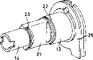
Fig. 4 is the stereogram of throttle body 10.
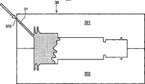
Fig. 5 is the explanatory drawing of the forming method of expression throttle body and spring section.
Fig. 6 is the explanatory drawing of the forming method of expression throttle body and spring section.
Fig. 7 is the explanatory drawing of the forming method of expression throttle body and spring section.
Fig. 8 is the explanatory drawing of the forming method of expression throttle body and spring section.
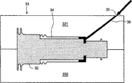
Fig. 9 is the explanatory drawing of the forming method of expression throttle body and spring section.
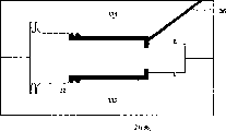
Figure 10 is the explanatory drawing of the forming method of expression throttle body and spring section.
Figure 11 is the sectional drawing of the engagement portion of expression valve portion and throttle valve body.
Figure 12 is the sectional drawing of the engagement portion of expression spring section and throttle valve body.
Figure 13 is a stereogram of removing the valve portion of spring section.
The sectional drawing of the conventional art of Figure 14 incomplete example of sealing that to be expression cause because of the angle tolerance of throttle valve body and butterfly valve portion.
The sectional drawing of the conventional art of Figure 15 incomplete example of sealing that to be expression cause because of the angle tolerance of throttle valve body and throttle body.
Among the figure: 1-cylinder head, 2-intakeport, 4-sucking pipe, 7-air filter housing, 8-throttle valve body, 10-throttle body, 11-valve portion, 12-axial region, 13-large-diameter portion branch, 15-sleeve, 21-spring section.
Embodiment
Below, with reference to the description of drawings one embodiment of the present invention.Fig. 2 is the main position sectional drawing of suction system that comprises the throttle valve gear of one embodiment of the present invention.In the figure, configuration Aspirating valves 3 on the intakeport 2 on the cylinder head 1 that is formed on internal-combustion engine.Import the sucking pipe 4 of mixed gass to intakeport 2, by be combined in the pipe box 5 on the cylinder head 1, thermal insulator 6, air filter housing 7, the throttle valve body 8 that forms with adiabatic material constitutes.The part of the sucking pipe 4 that forms in the bottom of air filter housing 7, spray-hole disposes combustion injection valve 9 towards sucking pipe 4 interiorly.Thermal insulator 6, in order to prevent directly to pass to air filter 7 or throttle valve body 8 from the heat of motor, the relatively low resin material of available heat resistance forms air filter 7 or throttle valve body 8.
Fig. 1 is the sectional drawing of throttle valve gear, and Fig. 3 is its side view.In Fig. 1 and Fig. 3, axial region 12 is made of the heavy caliber part 13 on the top that is positioned at Fig. 1 and the small-bore part 14 that is positioned at the bottom.Valve portion 11 and be rectangle at the sectional shape of the locational sucking pipe of configuration valve portion 11 at least, valve portion 11 is connected on the face of the section difference that is formed in the throttle body 8 to close the throttle valve state.This section is poor, forms (with reference to the sectional shape of the throttle body 8 of Fig. 2) by move sucking pipe 4 in the upstream side of valve portion 11 and downstream side.
That is, the bore of heavy caliber part 13, set for one side greater than the rectangle of valve portion 11 (be valve portion, with the overall dimensions of the direction of axial region 12 quadratures), the bore of small-bore part 14 is set the one side less than the rectangle of valve portion 11 for.Valve portion 11 is combined on heavy caliber part 13 and the small-bore part 14 along two ends, is positioned at the intermediate portion of heavy caliber part 13 and small-bore part 14.Heavy caliber part 13 is inserted in the outstanding sleeve 15 of throttle valve body 8, and small-bore part 14 is inserted in the madial wall 17 of the outstanding dual sleeve 16 of the opposition side of sleeve 15 by encircling 18.By packing ring 19, embed stop ring 20 at this protuberance, stop throttle body 10 to be deviate from from throttle valve body 8.
The spring section 21 that coats valve portion 11 is set in valve portion 11.Spring section 21 comprises respectively from the annulus 22,23 of valve portion 11 to heavy caliber part 13 and 14 extensions of small-bore part.The circumferential edges of annulus 22,23 in the easy deflection of part that is connected on the throttle valve body 8, improves adaptation, forms waveform.Spring section 21 is preferably formed by elastomeric polymer.Elastomeric polymer is the material of drug resistance excellence.The effect of spring section 21 as described later.
Periphery at sleeve 15 is provided with torsion spring 24, and axial region 12 is close to closing the throttle valve direction.One end of torsion spring 24 is fixed on the bottom of sleeve 15, and the other end is fixed on the lip part 25 that stretches out to the top of heavy caliber part 13.On lip part 25, along peripheral shape groove 26 circlewise, by these groove 26 guiding and throttle valve cable 27 is installed on lip part 25.One end of throttle valve cable 27 is combined on the lip part 25 with pin 28, and the other end is combined in the not shown throttle operation portion (in motorcycle, the handle of steering wheel) simultaneously.
Torsion spring 24 is installed on the axial region 12, so that valve portion 11 is close to contract fully throttle valve direction, throttle valve cable 27 is installed on the lip part 25, with when drawing this throttle valve cable 27, to the direction opposite with the action direction of torsion spring 24, rotate axial region 12, open throttle valve.
In the time of assembling throttle body 10 on throttle valve body 8,, insert throttle body 10 from small-bore part 14 sides with respect to sleeve 15.In addition, make small-bore part 14, connecting the madial wall 17 of sleeve 16, after give prominence to from madial wall its end, the end periphery of packing ring 19 and the small-bore part 14 of stop ring 20 embeddings.Because throttle body 10 is made of heavy caliber part 13 and small-bore part 14, so with respect to throttle valve body 8, be easy to assemble from a direction.
On the small-bore part 14 in conjunction with the connection shaft 29 that is used for throttle valve sensor 28 is attached on the small-bore part 14.Throttle valve sensor 28 for example is a variable resistor, can based on be attached at small-bore part 14 on the corresponding resistance value of rotational position of connection shaft 29, detect throttle valve opening.
Fig. 4 is the stereogram of the throttle body 10 finished.The symbolic representation identical with Fig. 1 and Fig. 3 is with a part.
Fig. 5~Figure 10 is the explanatory drawing of the forming method of expression throttle body 10 and spring section 21.In moulding, at first, as shown in Figure 5, prepare to be used for the mould 30 that the throttle body 10 of spring section 21 is removed in moulding (injection moulding).Mould 30 is made of patrix 301 and counterdie 302.In this mould 30, inject resin 31 from resin inlet 303.If form the state in mould 30, injected Fig. 6 of enough resins 31, just finish to inject, treat resin 31 coolings, slough mould 30 (direction to the arrow of Fig. 7 is deviate from).
Preparation is used on the part of the core of the throttle body 10 that so forms (promptly not the throttle body 10 of added resilience portion 21) 32 mould 33 (Fig. 8) of added resilience portion 21 integratedly.Mould 33 is made of patrix 331 and counterdie 332.If the part 32 of the core of throttle body 10 is embedded the inside of these moulds 33, as shown in Figure 9, just can form the space 34 of spring section 21 usefulness.Then, inject elastomeric polymer 36 from elastomeric polymer inlet 35.Figure 10 represents the state of filling elastomeric polymer in space 34.After the cooling, if mold removal 33 just can access, as spring section 21, the throttle body 10 (with reference to Fig. 4) of added resilience polymer 36 on the part 32 of the core of throttle body 10 integratedly.
Figure 11 is the sectional drawing of the engagement portion of expression valve portion 11 and throttle valve body 8.In the figure, when valve portion 11 contract fully throttle valve, valve portion 11 is close to the direction of arrow A by the elastic force of torsion spring 24.Thereby the section that the circumferential edges 211 of the spring section 21 around the coating valve portion 11 is pressed against throttle valve body 8 differs from 81,81.Spring section 21 is out of shape because of the section of being compressed against differs from 81,81, really contacts with the both sides that section differ from 81,81 face.
Figure 12 is the sectional drawing of the engagement portion of expression spring section 21 and throttle valve body 8.In the figure, throttle body 10, the state so that the direction applied thrust to arrow B increases the weight of is installed on the throttle valve body 8.Therefore, the annulus 22,23 of spring section 21, because of this thrust increases the weight of, the section that is compressed against throttle valve body 8 respectively differs from 83,84 the face, thereby deflection.Deflection depends on the deviation of the tolerance of throttle body 10 or throttle valve body 8, but in the example of Fig. 2, the deflection of annulus 23 is greater than annulus 22.
In addition, in Figure 12, resin portion 21 has connect the hole 37,38 be formed on heavy caliber part 13 and the small-bore part 14, the part 39,40 of stretching out in heavy caliber part 13 and small-bore part 14.Because by this part of stretching out 39,40 and annulus 22,23 clamping heavy caliber part 13 and small-bore parts 14, so the part 28 of the core of spring section 21 and throttle body 10 is combined closely more.
In order further to improve the combination of valve portion 11 and spring section 21,, can flow into the hole or the recess of elastomeric polymer in the time of also moulding can being arranged in valve portion 11.Figure 13 is a stereogram of removing the valve portion 11 of spring section 21.On the surface of valve portion 11, form a plurality of recesses 41.Recess 41 also can be located on the face of annulus 22,23 of driving fit spring section 21 of axial region 12.In addition, can replace recess 41 yet, the hole that connects valve portion 11 is set, its quantity does not limit.In addition, hole and recess also can mix existence.
So, according to present embodiment,, can carry out the sealing of throttle body 10 and throttle valve body 8 really by being located at the spring section 21 in the valve portion 11.
In addition, axial region 12 also can not be provided with the heavy caliber part of the diameter of axle that strengthens flange 181 sides, forms certain diameter of axle, also can reduce the diameter of axle of flange 181 sides.In such cases, owing to can insert throttle body 10 from a side of throttle valve body 8, so can use with 2 separate structures and promptly use parting plane longitudinally, separately support the axial region of bearing (axle sleeve) of the axle (in Fig. 1, the heavy caliber part) of flange 181 sides along axial region 12.
Claims (6)
1. a throttle valve gear is the throttle device of ic engine that has throttle body and accommodate the throttle valve body of this throttle body, it is characterized in that:
Described throttle body supports the axial region of this butterfly valve portion to constitute by the butterfly valve portion of the part of the air suction way in the described throttle valve body of switch with respect to described throttle valve body;
Coat described butterfly valve portion with spring section.
2. throttle valve gear as claimed in claim 1 is characterized in that: by at the enterprising one-step shaping of the throttle body of moulding and the dual forming method of additional elastomeric material is bonded in described spring section on the described throttle body.
3. throttle valve gear as claimed in claim 2 is characterized in that: be formed with recess and/or the hole that can immerse described elastic material on described throttle body.
4. as any one described throttle valve gear in the claim 1~3, it is characterized in that:
Described spring section prolongs to axial region from described valve portion, and this prolongation comprises the waveform circumferential edges;
Wall for described circumferential edges sidepiece butt is set on described throttle valve body.
5. as any one described throttle valve gear in the claim 1~4, it is characterized in that:
Described butterfly valve portion and described axial region are the integrative-structures that is made of resin;
Described axial region has the diameter bigger than the overall dimensions of this butterfly valve portion in a side of described butterfly valve portion, has the diameter littler than described overall dimensions at opposite side.
6. as claim 4 or 5 described throttle valve gears, it is characterized in that: described throttle body, with along the axis of described axial region in a side by the state of load, locate with respect to described throttle valve body along the direction of described axis.
Applications Claiming Priority (2)
| Application Number | Priority Date | Filing Date | Title |
|---|---|---|---|
| JP2004277760A JP2006090234A (en) | 2004-09-24 | 2004-09-24 | Throttle valve device |
| JP2004277760 | 2004-09-24 |
Publications (1)
| Publication Number | Publication Date |
|---|---|
| CN1752425A true CN1752425A (en) | 2006-03-29 |
Family
ID=36231453
Family Applications (1)
| Application Number | Title | Priority Date | Filing Date |
|---|---|---|---|
| CNA2005100910370A Pending CN1752425A (en) | 2004-09-24 | 2005-08-03 | Throttle device |
Country Status (5)
| Country | Link |
|---|---|
| JP (1) | JP2006090234A (en) |
| KR (1) | KR20060050617A (en) |
| CN (1) | CN1752425A (en) |
| BR (1) | BRPI0503752A (en) |
| TW (1) | TW200610885A (en) |
Cited By (2)
| Publication number | Priority date | Publication date | Assignee | Title |
|---|---|---|---|---|
| CN109306979A (en) * | 2018-10-29 | 2019-02-05 | 北京航天发射技术研究所 | A design method of hydraulic throttling control valve based on mechanism displacement velocity planning |
| CN109667674A (en) * | 2017-10-13 | 2019-04-23 | 台州荣茂电器有限公司 | A kind of motor cycle solar term valve arrangement |
Families Citing this family (1)
| Publication number | Priority date | Publication date | Assignee | Title |
|---|---|---|---|---|
| JP5256135B2 (en) * | 2009-07-08 | 2013-08-07 | 株式会社Roki | Structure of intake valve |
-
2004
- 2004-09-24 JP JP2004277760A patent/JP2006090234A/en active Pending
-
2005
- 2005-07-21 TW TW094124673A patent/TW200610885A/en not_active IP Right Cessation
- 2005-08-03 CN CNA2005100910370A patent/CN1752425A/en active Pending
- 2005-08-24 KR KR1020050077877A patent/KR20060050617A/en not_active Ceased
- 2005-09-19 BR BRPI0503752-2A patent/BRPI0503752A/en not_active IP Right Cessation
Cited By (3)
| Publication number | Priority date | Publication date | Assignee | Title |
|---|---|---|---|---|
| CN109667674A (en) * | 2017-10-13 | 2019-04-23 | 台州荣茂电器有限公司 | A kind of motor cycle solar term valve arrangement |
| CN109306979A (en) * | 2018-10-29 | 2019-02-05 | 北京航天发射技术研究所 | A design method of hydraulic throttling control valve based on mechanism displacement velocity planning |
| CN109306979B (en) * | 2018-10-29 | 2020-05-08 | 北京航天发射技术研究所 | A design method of hydraulic throttling control valve based on mechanism displacement velocity planning |
Also Published As
| Publication number | Publication date |
|---|---|
| BRPI0503752A (en) | 2006-05-09 |
| JP2006090234A (en) | 2006-04-06 |
| TW200610885A (en) | 2006-04-01 |
| TWI306487B (en) | 2009-02-21 |
| KR20060050617A (en) | 2006-05-19 |
Similar Documents
| Publication | Publication Date | Title |
|---|---|---|
| CN1267637C (en) | Engine blow-by gas distribution system | |
| EP1925809B1 (en) | Vehicle | |
| US20100006053A1 (en) | Air-intake device having plural valves for internal combustion engine | |
| CN1044733C (en) | Throttle device for internal combustion engine and method for manufacturing same | |
| CN1580522A (en) | Throttle body having internally connected double pipe structure | |
| CN1145979A (en) | Intake valve control system for internal combustion engine | |
| US7967092B2 (en) | Vehicle | |
| CN101069011A (en) | Air intake for internal combustion engines | |
| CN1752425A (en) | Throttle device | |
| US6986502B2 (en) | Throttle body | |
| CN1287217A (en) | Air-suction device for engine | |
| CN1955447A (en) | Throttle valve apparatus | |
| DE19717347C1 (en) | Method for manufacturing switching valve, e.g. for induction tract of IC engine | |
| US20080295800A1 (en) | Composite body bore band | |
| CN201461161U (en) | An anti-loosening structure of the breather pipe joint of the gasoline engine air intake system | |
| CN201011312Y (en) | A small displacement engine intake manifold | |
| US20070063164A1 (en) | Valve open and close apparatus | |
| EP3891377A1 (en) | Hand operated pump | |
| US6484695B1 (en) | Engine having compressed air assisted injection with secondary high speed fuel carburetor sandwich | |
| CN1871427A (en) | Internal combustion engine, an engine head and a fuel distribution line | |
| CN2760267Y (en) | Fuel-saving accelerating supercharger | |
| CN217177767U (en) | Oil-to-gas power speed increaser for mounting vehicle | |
| CN2823572Y (en) | Electric spraying gas saving valve for automobile | |
| CN2334878Y (en) | Two-stroke engine with crankcase pressure isolator and linear exhaust gas removal | |
| CN205422951U (en) | Take step motor idling flow control's air throttle |
Legal Events
| Date | Code | Title | Description |
|---|---|---|---|
| C06 | Publication | ||
| PB01 | Publication | ||
| C10 | Entry into substantive examination | ||
| SE01 | Entry into force of request for substantive examination | ||
| C12 | Rejection of a patent application after its publication | ||
| RJ01 | Rejection of invention patent application after publication |