CN1752902A - Electronic device and method for controlling image on screen - Google Patents
Electronic device and method for controlling image on screen Download PDFInfo
- Publication number
- CN1752902A CN1752902A CNA2005100594462A CN200510059446A CN1752902A CN 1752902 A CN1752902 A CN 1752902A CN A2005100594462 A CNA2005100594462 A CN A2005100594462A CN 200510059446 A CN200510059446 A CN 200510059446A CN 1752902 A CN1752902 A CN 1752902A
- Authority
- CN
- China
- Prior art keywords
- contacts
- electrical connection
- screen
- image
- switch
- Prior art date
- Legal status (The legal status is an assumption and is not a legal conclusion. Google has not performed a legal analysis and makes no representation as to the accuracy of the status listed.)
- Granted
Links
Images


Classifications
-
- B—PERFORMING OPERATIONS; TRANSPORTING
- B25—HAND TOOLS; PORTABLE POWER-DRIVEN TOOLS; MANIPULATORS
- B25B—TOOLS OR BENCH DEVICES NOT OTHERWISE PROVIDED FOR, FOR FASTENING, CONNECTING, DISENGAGING, OR HOLDING
- B25B15/00—Screwdrivers
- B25B15/02—Screwdrivers operated by rotating the handle
-
- H—ELECTRICITY
- H01—ELECTRIC ELEMENTS
- H01H—ELECTRIC SWITCHES; RELAYS; SELECTORS; EMERGENCY PROTECTIVE DEVICES
- H01H25/00—Switches with compound movement of handle or other operating part
- H01H25/04—Operating part movable angularly in more than one plane, e.g. joystick
- H01H25/041—Operating part movable angularly in more than one plane, e.g. joystick having a generally flat operating member depressible at different locations to operate different controls
-
- B—PERFORMING OPERATIONS; TRANSPORTING
- B25—HAND TOOLS; PORTABLE POWER-DRIVEN TOOLS; MANIPULATORS
- B25G—HANDLES FOR HAND IMPLEMENTS
- B25G1/00—Handle constructions
- B25G1/005—Handle constructions for screwdrivers, wrenches or spanners with additional levers, e.g. for increasing torque
-
- G—PHYSICS
- G06—COMPUTING OR CALCULATING; COUNTING
- G06F—ELECTRIC DIGITAL DATA PROCESSING
- G06F3/00—Input arrangements for transferring data to be processed into a form capable of being handled by the computer; Output arrangements for transferring data from processing unit to output unit, e.g. interface arrangements
- G06F3/01—Input arrangements or combined input and output arrangements for interaction between user and computer
- G06F3/03—Arrangements for converting the position or the displacement of a member into a coded form
- G06F3/033—Pointing devices displaced or positioned by the user, e.g. mice, trackballs, pens or joysticks; Accessories therefor
- G06F3/0338—Pointing devices displaced or positioned by the user, e.g. mice, trackballs, pens or joysticks; Accessories therefor with detection of limited linear or angular displacement of an operating part of the device from a neutral position, e.g. isotonic or isometric joysticks
-
- G—PHYSICS
- G06—COMPUTING OR CALCULATING; COUNTING
- G06F—ELECTRIC DIGITAL DATA PROCESSING
- G06F3/00—Input arrangements for transferring data to be processed into a form capable of being handled by the computer; Output arrangements for transferring data from processing unit to output unit, e.g. interface arrangements
- G06F3/01—Input arrangements or combined input and output arrangements for interaction between user and computer
- G06F3/048—Interaction techniques based on graphical user interfaces [GUI]
- G06F3/0484—Interaction techniques based on graphical user interfaces [GUI] for the control of specific functions or operations, e.g. selecting or manipulating an object, an image or a displayed text element, setting a parameter value or selecting a range
- G06F3/0485—Scrolling or panning
-
- G—PHYSICS
- G06—COMPUTING OR CALCULATING; COUNTING
- G06F—ELECTRIC DIGITAL DATA PROCESSING
- G06F2203/00—Indexing scheme relating to G06F3/00 - G06F3/048
- G06F2203/048—Indexing scheme relating to G06F3/048
- G06F2203/04806—Zoom, i.e. interaction techniques or interactors for controlling the zooming operation
-
- H—ELECTRICITY
- H01—ELECTRIC ELEMENTS
- H01H—ELECTRIC SWITCHES; RELAYS; SELECTORS; EMERGENCY PROTECTIVE DEVICES
- H01H2300/00—Orthogonal indexing scheme relating to electric switches, relays, selectors or emergency protective devices covered by H01H
- H01H2300/054—Application timeslot: duration of actuation or delay between or combination of subsequent actuations determines selected function
Landscapes
- Engineering & Computer Science (AREA)
- General Engineering & Computer Science (AREA)
- Theoretical Computer Science (AREA)
- Human Computer Interaction (AREA)
- Physics & Mathematics (AREA)
- General Physics & Mathematics (AREA)
- Mechanical Engineering (AREA)
- Position Input By Displaying (AREA)
- User Interface Of Digital Computer (AREA)
- Input From Keyboards Or The Like (AREA)
- Transforming Electric Information Into Light Information (AREA)
- Switches With Compound Operations (AREA)
- Telephone Set Structure (AREA)
Abstract
电子装置和屏幕上图像的控制方法。电子装置包括具有彼此间隔开的多个触点的开关。该多个触点被设计为独立建立电连接。控制器单元被设计为当该控制器单元在预定时间段内在至少两个触点处顺序地检测到电连接时指示对显示屏屏幕上的图像进行控制。利用在预定时间段内顺序地检测到触点处的电连接,实现了电子装置中的图像控制。可以实现简便的操作,来控制屏幕上的图像。可以利用传统的触点来建立电连接。可以通过简单的结构实现图像控制。
An electronic device and a method for controlling images on a screen. An electronic device includes a switch having a plurality of contacts spaced apart from each other. The plurality of contacts are designed to independently establish electrical connections. The controller unit is designed to instruct control of the image on the display screen when the controller unit sequentially detects an electrical connection at at least two contacts within a predetermined period of time. The image control in the electronic device is realized by sequentially detecting the electrical connections at the contacts within a predetermined period of time. Easy operation can be realized to control the image on the screen. The electrical connection can be established using conventional contacts. Image control can be realized with a simple structure.
Description
技术领域technical field
本发明涉及诸如个人数字助理(PDA)、蜂窝电话终端等的电子装置。具体地,本发明涉及包括显示屏的电子装置,该显示屏具有用于显示图像的屏幕。The present invention relates to electronic devices such as Personal Digital Assistants (PDAs), cellular phone terminals, and the like. In particular, the present invention relates to an electronic device including a display screen having a screen for displaying an image.
背景技术Background technique
蜂窝电话终端中通常安装有液晶显示(LCD)屏。所述LCD屏被设计为在屏幕上显示图像。可以在LCD屏的屏幕上显示各种图像。可以在蜂窝电话终端中安装滚动小键盘。蜂窝电话终端的用户对该滚动小键盘进行操作以控制图像在屏幕上的滚动。A liquid crystal display (LCD) screen is generally installed in a cellular phone terminal. The LCD screen is designed to display images on the screen. Various images can be displayed on the screen of the LCD panel. A scroll keypad may be installed in a cellular telephone terminal. The user of the cellular phone terminal operates the scroll keypad to control the scrolling of images on the screen.
在蜂窝电话终端中,滚动小键盘独立于所谓的十字小键盘。滚动小键盘通常由圆盘状或圆柱形旋转元件构成。为了在蜂窝电话终端中实现滚动小键盘,结构或机构会变得复杂。这不是优选的。In cellular phone terminals, the scroll keypad is independent of the so-called cross keypad. Rolling keypads are usually constructed of disc-shaped or cylindrical rotating elements. In order to implement the scroll keypad in a cellular phone terminal, the structure or mechanism becomes complicated. This is not preferred.
发明内容Contents of the invention
因此,本发明的一个目的是提供一种实现简便结构以对显示屏屏幕上的图像进行控制的电子装置。本发明的一个目的是提供一种对显示屏屏幕上的图像进行控制的方法以及程序指令,从而大大有助于实现所述电子装置。Accordingly, an object of the present invention is to provide an electronic device realizing a simple structure for controlling an image on a display screen. An object of the present invention is to provide a method of controlling images on a display screen and program instructions, thereby greatly assisting in realizing said electronic device.
根据本发明的第一方面,提供了一种电子装置,包括:显示屏,具有用于显示图像的屏幕;开关,具有彼此间隔开的多个触点(contact),所述多个触点被设计为独立地建立电连接;以及控制器单元,被设计为当控制器单元在预定时间段内在至少两个触点处顺序检测到电连接时指示对屏幕上的图像进行控制。According to a first aspect of the present invention, there is provided an electronic device comprising: a display screen having a screen for displaying an image; a switch having a plurality of contacts spaced apart from each other, the plurality of contacts being controlled by designed to independently establish the electrical connection; and a controller unit designed to instruct control of the image on the screen when the controller unit sequentially detects the electrical connection at at least two contacts within a predetermined period of time.
利用在预定时间段内顺序在触点处检测到的电连接来实现电子装置中的图像控制。可以实现简便的操作以实现对屏幕上图像的控制。此外,可以利用传统触点来建立电连接。可以通过简单的结构实现图像控制。Image control in an electronic device is implemented using electrical connections detected sequentially at contacts within a predetermined period of time. Easy operation can be realized to realize the control of the image on the screen. Additionally, conventional contacts can be utilized to establish electrical connections. Image control can be realized with a simple structure.
控制器单元可以被设计为:当控制器单元在预定时间段内在至少两个触点处顺序检测到电连接时,指示在屏幕上滚动图像。在这种情况下,在开关中,电连接的触点沿着预定方向排列。当控制器单元检测到沿预定方向在多个触点处顺序建立了电连接时,控制器单元获准进行滚动操作作为对图像的控制。可以实现简便的操作来实现图像的滚动。由此,可以通过简单的结构实现图像的滚动。The controller unit may be designed to instruct scrolling of images on the screen when the controller unit sequentially detects electrical connections at at least two contacts within a predetermined period of time. In this case, in the switch, electrically connected contacts are arranged along a predetermined direction. When the controller unit detects that electrical connections are sequentially established at a plurality of contacts in a predetermined direction, the controller unit permits a scrolling operation as control of the image. Easy operation can be realized to realize the scrolling of the image. Thereby, image scrolling can be realized with a simple structure.
控制器单元可以根据建立电连接的触点的排列来确定一矢量。该矢量可以与滚动方向相关联。如果所述触点排列在纵向上,则可以建立取向为纵向的矢量。类似地,如果所述触点排列在横向上,则可以建立取向为横向的矢量。因此,可以通过简单的结构来实现向上、向下、向左以及向右的滚动。The controller unit may determine a vector based on the arrangement of contacts establishing the electrical connection. This vector can be associated with a scrolling direction. If the contacts are aligned in the longitudinal direction, a vector oriented in the longitudinal direction can be established. Similarly, if the contacts are aligned in the transverse direction, a vector oriented transversely can be established. Therefore, scrolling up, down, left, and right can be realized with a simple structure.
该开关可以将所述多个触点排列成三行三列的矩阵。用户可以沿短路径在开关上滑过触摸部(touch),以在触点处顺序建立电连接。例如,在顺序建立电连接的过程中,用户可以使用一个手指如拇指来操作所述开关。与传统电子装置相比,可以实现简便的操作。此外,所述电子装置可以使得十字上的触点用作四向(four-way)小键盘的组件。在这种情况下,开关不仅可以用作滚动小键盘,而且可以用作四向小键盘。The switch may arrange the plurality of contacts into a matrix of three rows and three columns. A user may slide a touch across the switch along a short path to sequentially establish an electrical connection at the contacts. For example, a user may use one finger, such as a thumb, to operate the switch during the sequence of establishing an electrical connection. Compared with conventional electronic devices, easy operation can be realized. In addition, the electronic device enables the contacts on the cross to be used as a component of a four-way keypad. In this case, the switch can be used not only as a scrolling keypad, but also as a four-way keypad.
控制器单元可以被设计为:当所述控制器单元在预定时间段内在至少两个触点处顺序检测到电连接时,指示在屏幕上缩放图像。在这种情况下,所述电连接的触点在开关中沿预定方向排列。当所述控制器单元沿预定方向在触点处检测到顺序建立了电连接时,控制器单元获准进行缩放操作,作为对图像的控制。可以实现简便的操作来实现对图像的缩放。因此,可以通过简单的结构实现对图像的缩放。The controller unit may be designed to instruct zooming of the image on the screen when the controller unit sequentially detects electrical connections at at least two contacts within a predetermined period of time. In this case, the electrically connected contacts are arranged in a predetermined direction in the switch. When the controller unit detects that the electrical connection is sequentially established at the contacts in a predetermined direction, the controller unit is permitted to perform a zoom operation as a control on the image. Easy operation can be realized to realize the zooming of the image. Therefore, image scaling can be realized with a simple structure.
所述电子装置可以被设计为基于电池驱动来工作。可以采用诸如干电池的原电池或者可充电的蓄电池作为所述电池。使用电池使得所述电子装置可以便于携带。此外,该电子装置使得只在触点电连接时耗费电力。这有助于在电子装置中减小电力消耗。由此,该电子装置根据电池的供电可以工作更长时间。The electronic device may be designed to operate on a battery drive. A primary battery such as a dry battery or a rechargeable secondary battery may be used as the battery. Using a battery allows the electronic device to be portable. Furthermore, the electronics are such that power is only consumed when the contacts are electrically connected. This helps to reduce power consumption in electronic devices. Therefore, the electronic device can work for a longer time with the power supplied by the battery.
根据本发明的第二方面,提供了一种对显示屏屏幕上的图像进行控制的方法,该方法包括以下步骤:在预定时间段内,顺序地对从开关中彼此间隔开的一组触点中选择的至少两个触点处的电连接进行检测,所述一组触点被设计为独立建立电连接;以及当检测到所述电连接时,实现对显示屏屏幕上的图像的控制。According to a second aspect of the present invention, there is provided a method of controlling an image on a display screen, the method comprising the steps of sequentially switching a set of contacts spaced apart from each other from a switch within a predetermined period of time detecting an electrical connection at at least two contacts selected from the group of contacts designed to independently establish an electrical connection; and when the electrical connection is detected, enabling control of an image on the display screen.
在该方法中,利用在预定时间段内对触点处的电连接的顺序检测来实现对图像的控制。可以实现简便的操作以实现对屏幕上图像的控制。此外,可以利用传统触点来建立电连接。可以通过简单的结构实现对图像的控制。In this method, image control is achieved by sequential detection of electrical connections at the contacts within a predetermined time period. Easy operation can be realized to realize the control of the image on the screen. Additionally, conventional contacts can be utilized to establish electrical connections. Image control can be realized through a simple structure.
该方法可以进一步包括以下步骤:当在从所述一组触点中选择的至少两个触点处顺序检测到电连接时,指示在屏幕上滚动图像。在这种情况下,在开关中,电连接的触点应该沿预定方向排列。可以实现简便的操作来实现对图像的滚动。由此,可以通过简单的结构实现对图像的滚动。The method may further include the step of instructing to scroll the image on the screen when electrical connection is sequentially detected at at least two contacts selected from the set of contacts. In this case, in the switch, the electrically connected contacts should be arranged in a predetermined direction. Simple operations can be realized to realize scrolling of images. Thus, scrolling of images can be realized with a simple structure.
可以根据建立电连接的触点的排列来确定一矢量。该矢量可以与滚动方向相关联。如果所述触点沿纵向排列,则可以建立取向为纵向的矢量。类似地,如果所述触点沿横向排列,则可以建立取向为横向的矢量。由此,可以通过简单的结构实现向上、向下、向左和向右的滚动。A vector can be determined from the arrangement of contacts that establish the electrical connection. This vector can be associated with a scrolling direction. If the contacts are aligned longitudinally, a vector oriented longitudinally can be established. Similarly, if the contacts are aligned laterally, a vector oriented laterally can be established. Thereby, scrolling up, down, left, and right can be realized with a simple structure.
该方法可以进一步包括以下步骤:当在从所述一组触点中选择的至少两个触点处顺序检测到电连接时,指示在屏幕上缩放图像。在这种情况下,在开关中,电连接的触点应该沿预定方向排列。可以实现简便的操作来实现对图像的缩放。由此,可以通过简单的结构实现对图像的缩放。The method may further include the step of instructing to zoom the image on the screen when electrical connection is sequentially detected at at least two contacts selected from the set of contacts. In this case, in the switch, the electrically connected contacts should be arranged in a predetermined direction. Easy operation can be realized to realize the zooming of the image. Thus, zooming of an image can be realized with a simple structure.
可以提供程序指令来实现上述方法。在这种情况下,包含有程序指令(用于对显示屏屏幕上的图像进行控制)的计算机可读存储介质可以包括:使得处理器在预定时间段内顺序地对从开关中彼此间隔开的一组触点中选择的至少两个触点处的电连接进行检测的计算机程序代码,所述一组触点被设计为独立地建立电连接;以及,使得处理器在检测到电连接时实现对显示屏屏幕上图像的控制的计算机程序代码。所述程序指令可以安装在个人数字助理(PDA)、蜂窝电话终端等中。Program instructions may be provided to implement the methods described above. In this case, a computer-readable storage medium embodying program instructions for controlling an image on a display screen may include causing the processor to sequentially switch the switches spaced apart from each other within a predetermined period of time. computer program code for detecting an electrical connection at at least two contacts selected from a set of contacts designed to independently establish an electrical connection; Computer program code for the control of images on a display screen. The program instructions can be installed in a personal digital assistant (PDA), a cellular phone terminal, or the like.
附图说明Description of drawings
结合附图,根据以下对优选实施例的说明,本发明的上述和其它目的、特征和优点将变得清楚,在附图中:The above and other objects, features and advantages of the present invention will become clear from the following description of preferred embodiments in conjunction with the accompanying drawings, in which:
图1是示意性地示出作为根据本发明实施例的电子装置的个人数字助理(PDA)的正视图;1 is a front view schematically showing a personal digital assistant (PDA) as an electronic device according to an embodiment of the present invention;
图2是示意性地示出容纳有开关按钮的圆顶开关(dome switch)的平面图;Fig. 2 is a plan view schematically showing a dome switch (dome switch) accommodating a switch button;
图3是沿图1中的线3-3截取的部分纵剖视图;Figure 3 is a partial longitudinal sectional view taken along line 3-3 in Figure 1;
图4是沿图1中的线4-4截取的部分纵剖视图;Figure 4 is a partial longitudinal sectional view taken along line 4-4 in Figure 1;
图5是印刷电路板的平面图,用于示意性地示出开关按钮上的突起的排列;5 is a plan view of a printed circuit board for schematically showing the arrangement of protrusions on the switch button;
图6是示意性地示出PDA的电路的框图;Fig. 6 is the block diagram that schematically shows the circuit of PDA;
图7示意性地示出根据具体示例在液晶显示(LCD)屏的屏幕上的显示;Fig. 7 schematically shows a display on a screen of a liquid crystal display (LCD) screen according to a specific example;
图8是印刷电路板的平面图,用于示意性地示出根据具体示例的移动矢量;8 is a plan view of a printed circuit board for schematically illustrating movement vectors according to a specific example;
图9是示出根据具体示例的安装在PDA中的实现软件程序的处理的流程图;FIG. 9 is a flowchart illustrating a process of implementing a software program installed in a PDA according to a specific example;
图10示意性地示出根据具体示例的滚动后的显示;Fig. 10 schematically shows a scrolled display according to a specific example;
图11是印刷电路板的平面图,用于示意性地示出根据具体示例的移动矢量;11 is a plan view of a printed circuit board for schematically illustrating movement vectors according to a specific example;
图12示意性地示出根据具体示例的滚动后的显示;Fig. 12 schematically shows a scrolled display according to a specific example;
图13是印刷电路板的平面图,用于示意性地示出根据具体示例的移动矢量;13 is a plan view of a printed circuit board for schematically illustrating movement vectors according to a specific example;
图14是印刷电路板的平面图,用于示意性地示出根据具体示例的移动矢量;14 is a plan view of a printed circuit board for schematically illustrating movement vectors according to a specific example;
图15是印刷电路板的平面图,用于示意性地示出根据具体示例的移动矢量;15 is a plan view of a printed circuit board for schematically illustrating movement vectors according to a specific example;
图16是印刷电路板的平面图,用于示意性地示出根据具体示例的移动矢量;16 is a plan view of a printed circuit board for schematically illustrating movement vectors according to a specific example;
图17是印刷电路板的平面图,用于示意性地示出根据具体示例的移动矢量;以及FIG. 17 is a plan view of a printed circuit board for schematically illustrating a movement vector according to a specific example; and
图18是印刷电路板的平面图,用于示意性地示出根据具体示例的移动矢量。Fig. 18 is a plan view of a printed circuit board for schematically showing movement vectors according to a specific example.
具体实施方式Detailed ways
图1示意性地示出个人数字助理(PDA),作为根据本发明实施例的电子装置的具体示例。例如,PDA 11包括外壳,该外壳用于包含诸如母板的印刷电路板。在母板上安装有电子电路元件,例如用作控制器单元的中央处理单元(CPU)、存储器等。CPU例如根据临时存储在存储器中的软件程序和数据进行各种处理。FIG. 1 schematically shows a personal digital assistant (PDA), as a specific example of an electronic device according to an embodiment of the present invention. For example, the PDA 11 includes a housing for containing a printed circuit board such as a motherboard. Electronic circuit components such as a central processing unit (CPU) serving as a controller unit, memory, etc. are mounted on the motherboard. The CPU performs various processes based on, for example, software programs and data temporarily stored in the memory.
外壳12中安装有诸如液晶显示(LCD)屏13的平面显示屏。LCD屏13在外壳12表面的矩形窗口14内限定了一屏幕。一触摸屏板可以叠置在LCD屏13的表面上。例如,可以使用触笔(stylus)来通过触摸屏板向CPU输入指令和数据。A flat display screen such as a liquid crystal display (LCD)
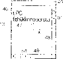
LCD屏13的屏幕设定有平面x-y坐标系。该x-y坐标系的y轴在纵向限定屏幕纵坐标。类似地,该x-y坐标系统的x轴在横向限定屏幕横坐标。当图像包括沿屏幕横向排列的字符(如英文单词)时,字符行平行于x轴延伸。如果沿纵向在屏幕上滚动图像,则字符行沿y轴方向平移。如果随后沿横向滚动图像,则字符行沿x轴方向平移。The screen of the
在外壳12中限定有正方形开口15。在开口15内设置有正方形开关按钮16。在开关按钮16的表面上刻有上三角标记16a、下三角标记16b、左三角标记16c以及右三角标记16d。上三角标记16a和下三角标记16b限定了y轴。左三角标记16c和右三角标记16d限定了x轴。因此,根据上、下、左、右三角标记16a至16d,在开关按钮16的表面上建立了平面x-y坐标系。开关按钮16的x-y坐标系反映LCD屏13的x-y坐标。PDA 11的用户可以使用开关按钮16来向CPU输入各种指令。A
PDA 11被设计为基于从电池(未示出)提供的电力工作。例如,在外壳12的背部可以限定一封闭空间,以容纳电池。诸如干电池的原电池或可充电的蓄电池可以用作所述电池。使用电池使得PDA 11可以便于携带。The PDA 11 is designed to operate on power supplied from a battery (not shown). For example, an enclosed space may be defined at the back of the
如图2所示,开关组22位于外壳12的内部空间内的母板21上。上述开关按钮16容纳在该开关组22上。在这种情况下,开关按钮16可以采用圆形,只要开关按钮16完全容纳在开关组22上即可。开关组22包括位于3×3(即,具有三行和三列)的矩阵中的圆顶开关23a至23i。圆顶开关23a至23i可以在行和列上彼此均等地间隔开。As shown in FIG. 2 , the
用作支点(fulcrum)的圆顶开关23e位于开关按钮16的中央,即位于x-y坐标系的原点。用作四向十字小键盘元件的圆顶开关23d、23f、23b、23h位于正方形开关按钮16的上侧、下侧、左侧、右侧的中央位置。圆顶开关23a、23c、23g、23i位于正方形开关按钮16的角部。利用圆顶开关23a、23c、23g、23i来如下所述在LCD屏屏幕上滚动图像。A
如图3所示,开关按钮16包括按钮主体26以及粘附于按钮主体26的背面或下面的弹性部件27。按钮主体26例如可以由诸如聚碳酸酯的硬塑性材料制成。在这种情况下,可以采用模制工艺来形成按钮主体26。开关按钮16在开口15内通过弹性支承体28受到支承。弹性部件27和弹性支承体28例如可以由诸如橡胶的弹性树脂材料制成。As shown in FIG. 3 , the
在弹性部件27上与各个圆顶开关23a至23i相对的位置处形成有突起29a至29i。突起29a至29i可以与弹性部件27一体化。突起29a至29i按与圆顶开关23a至23i相同的方式排列为3×3(即具有三行和三列)的矩阵。突起29a至29i在与母板21的表面垂直的方向上延伸。开关按钮16被允许响应于作用在按钮主体26的上表面上的迫力朝着外壳12的内部空间向下运动。Protrusions 29a to 29i are formed on the elastic member 27 at positions opposed to the
与圆顶开关23e相对的突起29e从弹性部件27直竖起第一高度。与圆顶开关23b、23h相对的突起29b、29h从弹性部件27直竖起小于第一高度的第二高度。类似地,与圆顶开关23d、23f相对的突起29d、29f从弹性部件27直竖起第二高度。The protrusion 29e opposite to the
如图4所示,与圆顶开关23c、23i相对的突起29c、29i从弹性部件27直竖起比第一高度和第二高度小的第三高度。类似地,与圆顶开关23a、23g相对的突起29a、29g从弹性部件27直竖起第三高度。As shown in FIG. 4, the protrusions 29c, 29i opposed to the dome switches 23c, 23i stand upright from the elastic member 27 by a third height smaller than the first height and the second height. Similarly, protrusions 29 a , 29 g opposite to the dome switches 23 a , 23 g stand upright from the resilient member 27 by a third height.
如图3和图4中所示,各个圆顶开关23a至23i包括接合到母板21的表面的圆顶状电极31。电极31包括由树脂膜制成的圆顶。该圆顶形成母板21的表面与其自身之间的间隙。在圆顶内形成有上导电膜。所述树脂膜可以由诸如聚酯、聚碳酸酯等的树脂材料制成。As shown in FIGS. 3 and 4 , each of the dome switches 23 a to 23 i includes a dome-shaped electrode 31 bonded to the surface of the
母板21的表面上形成有下导电膜。下导电膜位于与上导电膜以一距离相对的位置处。上导电膜和下导电膜分别连接到散布于母板21上的导电图案。当在与外壳12的表面垂直的方向上按下开关按钮16时,开关按钮16的突起29a至29i朝着母板21的表面驱动圆顶的顶部,直至上导电膜与下导电膜相互接触。这样可以在圆顶开关23a至23i中建立电连接。上导电膜和下导电膜形成圆顶开关23a至23i的触点。A lower conductive film is formed on the surface of the
在电极31的圆顶中限定有气孔32。该气孔32用于实现空气在内部空间与外部之间的贯通。当圆顶的顶部被按下时,圆顶内部的空气通过气孔32排出。这使圆顶可以发生变形。如上所述,圆顶的变形用于建立上述的电连接。当圆顶被解除压力时,空气通过气孔32导入圆顶的内部空间。圆顶恢复到原状。电连接断开。Air holes 32 are defined in the dome of the electrode 31 . The air hole 32 is used to realize the passage of air between the inner space and the outside. The air inside the dome is expelled through the air holes 32 when the top of the dome is pressed down. This allows the dome to deform. As mentioned above, the deformation of the dome is used to establish the electrical connection described above. When the dome is depressurized, air is introduced through the air holes 32 into the interior space of the dome. The dome was restored to its original shape. The electrical connection is broken.
如图5所示,例如,当朝着母板21的表面按下圆顶开关23g附近的开关按钮16右上角时,突起29g朝着母板21的表面绕着圆顶开关23e的顶部向下摆动。由此,响应于突起29g的摆动,在圆顶开关23g中建立了电连接。这里,圆顶开关23e被设计为与其它圆顶开关23a至23d以及23f至23i相比,承受更大压力。由此,使得圆顶开关23e可以用作支点。避免了在圆顶开关23e处建立电连接。此外,由于突起29e的第一高度被设置为大于突起29d、29h的第二高度,所以,也避免了在圆顶开关23d、23h处建立电连接。具体地说,在位于行R2和R3以及列C1和C2上的圆顶开关23a至23f、23h和23i处没有建立电连接。As shown in FIG. 5, for example, when the upper right corner of the
当在圆顶开关23h附近的三角标记16d处按下开关按钮16时,突起29h朝着母板21的表面绕着圆顶开关23e的顶部向下摆动。由此,响应于突起29h的摆动,在圆顶开关23h中建立了电连接。如上所述,避免了在圆顶开关23e处建立电连接。此外,由于突起29g、29i的第三高度被设置为小于突起29h的第二高度,所以也避免了在圆顶开关23g、23i处建立电连接。具体地说,在位于行R1和R3以及列C1和C2上的圆顶开关23a至23g以及23i处没有建立电连接。When the
此外,当在圆顶开关23e上的x-y坐标系原点处按下开关按钮16时,突起29e朝着母板21的表面向下移动。响应于突起29e的向下移动,在圆顶开关23e处建立了电连接。如上所述,突起29e的第一高度被设置为大于其它突起29a至29d以及29f至29i的第二高度和第三高度,从而在圆顶开关23a至23d以及23f至23i处没有建立电连接。这样,开关组22使得可以响应于开关按钮16的向下移动在圆顶开关23a至23i处分别建立电连接。Furthermore, when the
如图6所示,控制器单元或CPU 33连接到圆顶开关23a至23i。当在圆顶开关23a至23i处建立了电连接时,圆顶开关23a至23i持续向CPU 33输出指明连接的信号。当解除电连接时,圆顶开关23a至23i停止输出信号。由此,使得CPU 33可以检测到各个圆顶开关23a至23i处的电连接和断开。如稍后所详述,CPU 33被设计为指示对在显示器屏幕上滚动和缩放图像进行控制。As shown in FIG. 6, a controller unit or CPU 33 is connected to the dome switches 23a to 23i. When electrical connection is established at the dome switches 23a to 23i, the dome switches 23a to 23i continuously output a signal indicating the connection to the CPU 33. When the electrical connection is released, the dome switches 23a to 23i stop outputting signals. This allows the CPU 33 to detect electrical connection and disconnection at the
CPU 33根据建立电连接的圆顶开关23a至23i的排列来识别移动矢量。CPU 33被设计为将该矢量与滚动方向和缩放类型相关联。所述矢量的起点设置在圆顶开关23a、23c、23g、23i处。稍后将详细说明对该矢量的确定。CPU 33响应于开关按钮16的向下移动,指示对图像的滚动或缩放。这里,滚动方向被设置为沿着LCD屏13上的屏幕的纵向和横向。图像缩放包括放大和缩小。The CPU 33 recognizes the movement vector from the arrangement of the dome switches 23a to 23i establishing electrical connection. The CPU 33 is designed to associate this vector with the scroll direction and zoom type. The starting points of the vectors are set at the
定时器34连接到CPU 33。当CPU 33在圆顶开关23a、23c、23g、23i中的至少一个处检测到电连接时,CPU 33指示定时器34开始计时。当在定时器34处经过了预定时间段时,定时器34向CPU 33提供指出经过了预定时间段的信号。例如,对于预定时间段,可以设置100毫秒。The timer 34 is connected to the CPU 33. When the CPU 33 detects an electrical connection at at least one of the
随机存取存储器(RAM)36和非易失性存储器37连接到CPU 33。可以使用闪存作为非易失性存储器37。可以将诸如操作系统(OS)38等的基本软件程序以及应用软件程序39存储在非易失性存储器37中。例如,CPU 33被设计为根据OS 38和临时存储在RAM 36中的应用软件程序39执行处理。稍后将详细说明应用软件程序39。A random access memory (RAM) 36 and a nonvolatile memory 37 are connected to the CPU 33. A flash memory can be used as the nonvolatile memory 37 . Basic software programs such as an operating system (OS) 38 and application software programs 39 can be stored in the nonvolatile memory 37 . For example, the CPU 33 is designed to execute processing in accordance with the OS 38 and application software programs 39 temporarily stored in the RAM 36. The application software program 39 will be described in detail later.
视频芯片41连接到CPU 33。视频RAM 42连接到视频芯片41。视频芯片41被设计为根据来自CPU 33的指令生成背景、文本以及图形图像。生成的背景、文本以及图形图像存储在视频RAM 42中。背景、文本以及图形图像的合成图像显示在LCD屏13的屏幕上。The video chip 41 is connected to the CPU 33. Video RAM 42 is connected to video chip 41. The video chip 41 is designed to generate background, text and graphic images according to instructions from the CPU 33. The generated background, text and graphic images are stored in video RAM 42. A composite image of the background, text, and graphic images is displayed on the screen of the
如图7所示,当启动诸如文字处理器的应用软件程序39时,在LCD屏13的屏幕45上显示窗口46。例如,OS 38用于生成窗口46的图像。例如,在窗口46中显示沿平行于x轴的横向排列的文本47。由此,在屏幕45上显示包括窗口46和文本47的合成图像。As shown in FIG. 7, when an application software program 39 such as a word processor is started, a
在窗口46的右手端设置有垂直滚动条48。利用垂直滚动条48来实现文本47在纵向上的滚动。在窗口46的下端设置有水平滚动条49。利用水平滚动条49来实现文本47在横向上的滚动。在垂直滚动条48和水平滚动条49内分别限定有滚动块51、51。当滚动块51在垂直滚动条48内沿纵向移动时,文本47沿纵向滚动。当滚动块51在水平滚动条49内沿横向移动时,文本47沿横向滚动。At the right-hand end of the window 46 a
在窗口46内显示光标52。光标52被设计为在纵向和横向上以文本47中的字符的高度和宽度移动。利用开关按钮16来实现光标52的移动。例如,当响应于开关按钮16的向下移动而在圆顶开关23d、23f、23b、23h中的任何一个处检测到电连接时,CPU 33进行操作以在屏幕45上沿纵向和横向移动光标52。在这种情况下,开关按钮16用作四向十字小键盘。当光标52在屏幕45下端的下方向下移动时,文本47在屏幕45中向上移动。当光标52向右移动超过屏幕45的右手端时,文本47在屏幕45中向左移动。A
现在,假定PDA 11的用户想要在LCD屏13的屏幕45上沿横向滚动图像。这里,以上述方式在屏幕45上显示包括窗口46和文本47的合成图像。CPU 33执行存储在非易失性存储器37中的应用软件程序39。CPU33监视是否在圆顶开关23a至23i处建立了任何电连接。如果PDA 11的用户如图8所示地按下开关按钮16的左上角,则突起29a朝着母板21的表面向下移动。突起29a的向下移动用于建立圆顶开关23a处的电连接。Now, assume that the user of the PDA 11 wants to scroll images horizontally on the
CPU 33从圆顶开关23a接收指出电连接的信号。由此,在图9中的步骤S1,CPU 33检测到圆顶开关23a处的电连接。CPU 33在步骤S2对该对象圆顶开关是否为圆顶开关23a、23c、23i、23g中的任何一个进行判断。这里,由于电连接是在圆顶开关23a处建立的,所以CPU 33的处理前进到步骤S3。在步骤S3,CPU 33向定时器34提供指出启动时钟的信号。定时器34接收到该信号,从而定时器34开始计时。The CPU 33 receives a signal indicating electrical connection from the
然后,在步骤S4,CPU 33对是否在圆顶开关23b至23i中的任何一个处建立了电连接进行判断。例如,如果用户在按下开关按钮16上的左上角之后连续按下上侧中间位置和右上角,则突起29d、29g顺序地朝着母板21的表面向下移动。突起29d、29g的向下移动导致在圆顶开关23d、23g处顺序地建立电连接。当CPU 33在从定时器34接收到指出经过了预定时间段的信号之前就接收到指出圆顶开关23d、23g处的电连接的信号时,CPU 33的处理前进到步骤S5。如果CPU 33在接收到指出经过了预定时间段的信号之前未接收到指出所述电连接的信号,则CPU 33结束针对滚动的操作。Then, in step S4, the CPU 33 judges whether an electrical connection is established at any one of the dome switches 23b to 23i. For example, if the user successively presses the upper middle position and the upper right corner after pressing the upper left corner on the
如图8所示,CPU 33在步骤S5根据圆顶开关23a、23d、23g的排列来识别移动矢量53。这里,将矢量53限定为穿过圆顶开关23a、23d、23g的中心。CPU 33将矢量53分解为x分量和y分量。可以根据电连接位置的移动量来计算x分量和y分量。这里,电连接的位置在行R1上从列C1移动到列C3,从而将移动量确定为三列。As shown in FIG. 8, the CPU 33 recognizes the movement vector 53 in step S5 based on the arrangement of the
然后,CPU 33在步骤S6对移动量是否等于三列或三行进行判断。这里,由于检测到了三列的移动,所以CPU 33的处理前进到步骤S7。CPU 33在步骤S7对矢量53是否被限定为平行于x轴或y轴进行判断。由于在这种情况下矢量53被限定为平行于x轴,所以CPU 33的处理前进到步骤S8。在步骤S8,CPU 33根据矢量53的方向来确定滚动方向。这里,由于矢量53被限定为沿着屏幕45的向右方向,所以CPU 33将矢量53与沿向右方向的图像滚动相关联。CPU 33在步骤S9向视频芯片41提供指示图像滚动的信号。如果移动量未到达三行或三列,则CPU 33结束针对滚动的操作。Then, the CPU 33 judges in step S6 whether the amount of movement is equal to three columns or three rows. Here, since the movement of three columns is detected, the processing of the CPU 33 proceeds to step S7. The CPU 33 judges in step S7 whether the vector 53 is defined to be parallel to the x-axis or the y-axis. Since the vector 53 is defined parallel to the x-axis in this case, the processing of the CPU 33 proceeds to step S8. In step S8, the CPU 33 determines the scrolling direction according to the direction of the vector 53. Here, since the vector 53 is defined along the rightward direction of the
然后,视频芯片41将图像在屏幕45上移动预定量。可以预先对所述量进行设置。将图像平行于x轴向左平移。如图10所示,文本47平行于x轴向左移动。在这种情况下,滚动块51在水平滚动条49内向右移动。光标52与文本47一起向左移动。这样,顺序检测到行R1上的圆顶开关23a、23d、23g处的电连接使得能够沿着向右方向滚动图像。如果矢量53限定为向左方向(与上述向右方向相反),则可以在屏幕45上沿向左方向滚动图像。Then, the video chip 41 moves the image on the
接下来,假定用户想要在LCD屏13的屏幕45上沿纵向滚动图像。这里,以上述方式在屏幕45上显示包括窗口46和文本47的合成图像。CPU 33监视在圆顶开关23a至23i处是否建立了电连接。当用户如图11所示地按下开关按钮16的右上角时,CPU 33在步骤S1检测到圆顶开关23g处的电连接。由于在圆顶开关23g处建立了电连接,所以CPU 33的处理经过步骤S2前进到步骤S3。CPU 33在步骤S3向定时器34提供指出启动时钟的信号。Next, assume that the user wants to scroll images in the vertical direction on the
然后,CPU 33在步骤S4对是否在圆顶开关23a至23f以及23h至23i中的任何一个处建立了电连接进行判断。例如,如果用户如图11所示地在按下开关按钮16上的右上角之后连续按下右侧中间位置和右下角,则在圆顶开关23h、23i处顺序地建立电连接。如果CPU 33在从定时器34接收到指出经过了预定时间段的信号之前就接收到指出圆顶开关23h、23i处的电连接的信号,则CPU 33的处理前进到步骤S5。Then, the CPU 33 judges in step S4 whether an electrical connection is established at any one of the dome switches 23a to 23f and 23h to 23i. For example, if the user successively presses the right middle position and the lower right corner after pressing the upper right corner on the
CPU 33在步骤S5根据圆顶开关23g、23h、23i的排列对移动矢量54进行识别。这里,将矢量54限定为穿过圆顶开关23g、23h、23i的中心。由于电连接的位置在列C3上从行R1移动到行R3,所以将移动量确定为三行。The CPU 33 recognizes the
然后,CPU 33在步骤S6对移动量是否等于三列或三行进行判断。这里,由于检测到三行的移动,所以CPU 33的处理前进到步骤S7。由于在这种情况下矢量54被限定为平行于y轴,所以CPU 33的处理前进到步骤S8。CPU 33在步骤S8根据矢量54的方向来确定滚动方向。这里,因为矢量54被限定为沿着屏幕45的向下方向,所以CPU 33将矢量54与沿向下方向的图像滚动相关联。CPU 33在步骤S9向视频芯片41提供指示滚动图像的信号。Then, the CPU 33 judges in step S6 whether the amount of movement is equal to three columns or three rows. Here, since the movement of three lines is detected, the processing of the CPU 33 proceeds to step S7. Since the
然后,视频芯片41将图像在屏幕45上移动预定量。由此,如图12所示,文本47在屏幕45上与y轴平行地向上平移。在这种情况下,滚动块51在垂直滚动条51内向下移动。光标52与文本47一起向上移动。顺序检测到列C3上的圆顶开关23g、23h、23i处的电连接使得能够沿向下方向滚动图像。如果矢量54被限定为沿着向上方向(与上述向下方向相反),则可以在屏幕45上沿向上方向滚动图像。Then, the video chip 41 moves the image on the
可以在圆顶开关23a至23i中不按照上述方式以三行或三列地建立电连接以实现图像滚动。例如,可以至少在圆顶开关23a、23d处顺序地建立电连接,以执行图像沿向右方向的滚动。具体地说,在CPU 33中可以不检测圆顶开关23g处的电连接。此外,可以至少在圆顶开关23g、23h处顺序地建立电连接,以执行图像沿向下方向的滚动。具体地说,在CPU33中可以不检测圆顶开关23i处的电连接。Electrical connections may be made in the dome switches 23a to 23i not in the above-described manner in three rows or columns to realize image scrolling. For example, electrical connections may be sequentially established at least at the
接下来,假定在圆顶开关23d、23f、23b、23h处建立电连接。以上述方式在屏幕45上显示包括窗口46和文本47的合成图像。例如,当PDA11的用户在三角标记16a处按下开关按钮16时,在圆顶开关23d处建立电连接。在图9中的步骤S1,CPU 33检测到电连接。由于电连接是在圆顶开关23d处建立的,所以CPU 33的处理前进到步骤S10。CPU 33执行十字小键盘的功能。这里,CPU 33检测到向上小键盘的标识。由此,光标52在屏幕45上向上移动。当在光标52到达了屏幕45的上端之后仍保持在三角箭头16a处按下开关按钮16时,图像响应于光标52的向上移动而向上滚动。文本47在屏幕45上向下移动。Next, it is assumed that electrical connection is established at the
上述的图像滚动可以允许在圆顶开关23d、23g处同时建立电连接。在这种情况下,CPU 33在步骤S1检测到圆顶开关23g处的电连接。如果之后以与上述方式相同的方式在预定时间段内在圆顶开关23h、23i处顺序地检测到电连接,则可以建立移动矢量54。然后,CPU 33实现步骤S6到S9的处理。这里,可以简单地忽略圆顶开关23d处的电连接。图像在屏幕45上向下滚动。可以实现开关按钮16的可靠操作,以执行图像滚动。The image scrolling described above may allow simultaneous establishment of electrical connections at the
如图13所示,上述的图像滚动可以允许例如当在圆顶开关23g、23h、23i处顺序地建立电连接时在圆顶开关23e、23h处同时建立电连接。在这种情况下,如果如上所述地在预定时间段内在圆顶开关23g、23h、23i处顺序地检测到电连接,则可以建立移动矢量54。然后,CPU 33实现步骤S6到S9的处理。这里,可以简单地忽略圆顶开关23e处的电连接。图像在屏幕45上向下滚动。可以实现开关按钮16的可靠操作,以执行图像滚动。As shown in Fig. 13, image scrolling as described above may allow, for example, electrical connections to be established simultaneously at
如图14所示,上述的图像滚动可以允许例如当在圆顶开关23g、23h、23i处顺序地建立电连接时在圆顶开关23i、23f处同时建立电连接。在这种情况下,如果如上所述地在预定时间段内在圆顶开关23g、23h、23i处顺序地检测到电连接,则可以建立移动矢量54。然后,CPU 33实现步骤S6到S9的处理。这里,可以简单地忽略圆顶开关23f处的电连接。图像在屏幕45上向下滚动。可以实现开关按钮16的可靠操作,以执行图像滚动。As shown in FIG. 14, image scrolling as described above may allow electrical connections to be made simultaneously at
如图15所示,上述的图像滚动可以允许例如当在圆顶开关23g、23h、23i处顺序地建立电连接时在成对圆顶开关23d、23g、23e、23h、23f、23i处同时建立电连接。在这种情况下,如果如上所述地在预定时间段内在圆顶开关23g、23h、23i处顺序地检测到电连接,则可以建立移动矢量54。然后,CPU 33实现步骤S6到S9的处理。这里,可以简单地忽略圆顶开关23d、23e、23f处的电连接。图像在屏幕45上向下滚动。可以实现开关按钮16的可靠操作,以执行图像滚动。As shown in FIG. 15, the image scrolling described above may allow simultaneous establishment of electrical connections at pairs of
如图16所示,上述的图像滚动可以允许例如经由圆顶开关23e、23h而在圆顶开关23g、23f处顺序地建立电连接。在这种情况下,CPU 33在步骤S5检测到穿过圆顶开关23g、23f的中心的矢量55。如上所述,CPU33计算电连接位置的移动量。这里,由于电连接从行R1上的列C3移动到行R3上的列C2,所以CPU 33确定y分量为三行、x分量为两列。具体地,矢量55被分解为平行于y轴的三行的第一矢量56、以及平行于x轴的两列的第二矢量57。由于第一矢量56在三行上延伸,所以CPU 33在步骤S6采用第一矢量。然后CPU 33实现步骤S7至S9的处理。这里,可以简单地忽略圆顶开关23h、23e处的电连接。图像在屏幕45上向下滚动。可以实现按钮开关16的可靠操作,以执行图像滚动。As shown in Fig. 16, image scrolling as described above may allow electrical connections to be established sequentially at
接下来,假定在圆顶开关23a处建立了电连接之后在预定时间段内没有在任一圆顶开关23b至23i处建立电连接。当CPU 33在步骤S1检测到圆顶开关23a处的电连接时,CPU 33的处理经过步骤S2前进到步骤S3。CPU 33在步骤S3向定时器34提供指出启动时钟的信号。这里,由于除了圆顶开关23a之外,没有在圆顶开关23b至23i处建立电连接,所以,当经过了预定时间段时,CPU 33从定时器34接收到指出经过了预定时间段的信号。在这种情况下可以简单地忽略圆顶开关23a处的电连接。CPU 33结束滚动操作。Next, assume that no electrical connection is established at any of the dome switches 23b to 23i within a predetermined period of time after the electrical connection is established at the
这种类型的PDA 11允许只根据预定时间段内在触点处顺序建立电连接就可以在屏幕上进行滚动。触点可以是传统圆顶开关23a至23i。可以通过简单的结构实现图像在LCD屏13的屏幕上的滚动。This type of PDA 11 allows scrolling on the screen only based on the sequential establishment of electrical connections at the contacts within a predetermined period of time. The contacts may be
此外,滚动方向与移动矢量相关联,所述移动矢量基于建立电连接的圆顶开关23a至23i的排列。可以在向上、向下、向左以及向右方向上建立该矢量。开关按钮16的简单操作使得能够通过简单的结构实现向上、向下、向左以及向右方向的滚动。Furthermore, the scrolling direction is associated with a movement vector based on the arrangement of the dome switches 23a to 23i establishing electrical connection. This vector can be established in up, down, left and right directions. Simple operation of the
此外,开关按钮16除了用作滚动用小键盘外,还可以用作四向十字小键盘。因为圆顶开关23a至23i排列为具有三行和三列的矩阵,所以用户可以沿短路径在开关按钮16上滑过触摸部以在圆顶开关23a至23i处顺序地建立电连接。例如,用户可以使用一根手指如拇指来操作开关按钮16。与传统PDA相比,可以实现简便的操作。In addition, the
接下来,假定PDA 11的用户想要缩小或减小LCD屏13的屏幕45上的图像。LCD屏13的屏幕45上显示有包括窗口46和文本47的合成图像。PDA 11的用户沿如图17所示的对角线按下开关按钮16。在图9中的步骤S1,CPU 33例如检测到圆顶开关23g处的电连接。这里,由于电连接是在圆顶开关23g处建立的,所以CPU 33的处理经过步骤S2前进到步骤S3。定时器34响应于接收到指出开始计时的信号,开始操作。Next, assume that the user of the PDA 11 wants to zoom out or reduce the image on the
例如,当用户将手指在开关按钮16上从右上角滑到左下角时,响应于突起29e、29c的向下移动,在圆顶开关23e、23c处顺序地建立电连接。如果CPU 33在从定时器34接收到指出经过了预定时间段的信号之前从圆顶开关23e、23c处顺序地接收到指出电连接的信号,则CPU 33的处理前进到步骤S5。For example, when a user slides a finger on the
CPU 33在步骤S5基于圆顶开关23g、23e、23c的排列来识别移动矢量61。在这种情况下,CPU 33检测到矢量61穿过圆顶开关23g、23e、23c的中心。CPU 33如上所述地计算电连接位置的移动量。这里,由于电连接从行R1上的列C3移动到行R3上的列C1,所以CPU 33确定y分量为三行、x分量为三列。具体地说,矢量61被分解为平行于y轴的三行的第一矢量62、以及平行于x轴的三列的第二矢量63。The CPU 33 identifies the
然后,CPU 33在步骤S6采用第一矢量62和第二矢量63。据此,在CPU 33中识别出沿对角线的原始矢量61。然后,CPU 33的处理前进到步骤S7。由于矢量61不平行于x轴和y轴中的任何一个,所以CPU 33的处理前进到步骤S11。CPU 33基于矢量61的方向确定放大或缩小。在CPU33中可以参照平行于y轴的第一矢量62的方向。由于第一矢量62被限定为沿着屏幕45上的向下方向,所以CPU 33将第一矢量62与缩小功能相关联。CPU 33在步骤S11向视频芯片41提供指示图像缩小或减小的信号。由此,视频芯片41响应于接收到该信号,在屏幕45上减小图像。检测到沿对角线在圆顶开关23g、23e、23c处顺序地建立了电连接使得能够缩小图像。Then, the CPU 33 adopts the
可以根据在预定时间段内在圆顶开关23a、23e、23i处顺序建立电连接来完成图像的缩小。另选地,可以根据在预定时间段内在圆顶开关23g、23c处顺序建立电连接来完成缩小。类似地,可以根据在预定时间段内在圆顶开关23a、23i处顺序建立电连接来完成缩小。The zooming out of the image may be accomplished by sequentially establishing electrical connections at the
接下来,假定PDA 11的用户想要在LCD屏13的屏幕45上放大或扩大图像。在屏幕45上以上述方式显示包括窗口46和文本47的合成图像。PDA 11的用户沿如图18所示的对角线按下开关按钮16。例如,在图9中的步骤S1,CPU 33检测到圆顶开关23i处的电连接。这里,由于电连接是在圆顶开关23i处建立的,所以CPU 33的处理经过步骤S2前进到步骤S3。定时器34响应于接收到指出开始计时的信号,开始操作。Next, assume that the user of the PDA 11 wants to zoom in or enlarge an image on the
例如,当用户将手指在开关按钮16上从右下角滑到左上角时,响应于突起29e、29a的向下移动,在圆顶开关23e、23a处顺序建立电连接。如果CPU 33在从定时器34接收到指出经过了预定时间段的信号之前顺序地从圆顶开关23e、23a处接收到指出电连接的信号,则CPU 33的处理前进到步骤S5。For example, when a user slides a finger on the
CPU 33在步骤S5基于圆顶开关23i、23e、23a的排列来识别移动矢量64。在这种情况下,CPU 33检测到矢量64穿过圆顶开关23i、23e、23a的中心。CPU 33如上所述地计算电连接位置的移动量。这里,由于电连接从行R3上的列C3移动到行R1上的列C1,所以CPU 33确定y分量为三行、x分量为三列。具体地,矢量64被分解为平行于y轴的三行的第一矢量65、以及平行于x轴的三列的第二矢量66。The CPU 33 identifies the
然后,CPU 33在步骤S6采用第一矢量65和第二矢量66。据此,在CPU 33中识别出沿对角线的原始矢量64。然后,CPU 33的处理前进到步骤S7。由于矢量64不平行于x轴和y轴中的任何一个,所以CPU 33的处理前进到步骤S11。CPU 33根据矢量64的方向确定放大或缩小。由于第一矢量65被限定为沿着屏幕45上的向上方向,所以CPU 33将第一矢量65与放大功能相关联。CPU 33在步骤S11向视频芯片41提供指示放大或扩大图像的信号。由此,视频芯片41响应于接收到该信号,在屏幕45上扩大图像。检测到沿对角线在圆顶开关23i、23e、23a处顺序地建立了电连接使得能够放大图像。Then, the CPU 33 adopts the
可以根据在预定时间段内在圆顶开关23c、23e、23g处顺序建立电连接来完成图像的放大。另选地,可以根据在预定时间段内在圆顶开关23i、23a处顺序建立电连接来完成缩小。类似地,可以根据在预定时间段内在圆顶开关23c、23g处顺序建立电连接来完成放大。Magnification of the image may be accomplished by sequentially establishing electrical connections at the dome switches 23c, 23e, 23g within a predetermined period of time. Alternatively, zooming out may be accomplished based on sequentially establishing electrical connections at the
这种类型的PDA 11使得当在LCD屏13的屏幕上进行缩放时,可以顺序检测到沿预定方向排列的至少一对圆顶开关处的电连接。具体地说,可以在位于三个连续圆顶开关端部的圆顶开关处检测到电连接。这些触点可以为传统圆顶开关23a至23i。可以通过简单的结构实现在LCD屏13的屏幕上缩放图像。This type of PDA 11 makes it possible to sequentially detect the electrical connection at at least one pair of dome switches arranged in a predetermined direction when zooming in on the screen of the
此外,开关按钮16除了用作缩放用小键盘,还可以用作四向十字小键盘。因为圆顶开关23a至23i排列为具有三行和三列的矩阵,所以用户可以沿短路径在开关按钮16上滑过触摸部以在圆顶开关23a至23i处顺序建立电连接。例如,用户可以使用一根手指如拇指来操作开关按钮16。与传统PDA相比,可以实现简便的操作。In addition, the
上述PDA 11可以允许响应于顺序建立电连接过程中的最末圆顶开关23a至23i处的持续电连接而连续进行滚动或缩放。例如,在即使在CPU33已从定时器34接收到指出经过了预定时间段的信号之后CPU 33仍然保持从圆顶开关23a至23i接收到指出电连接的信号时,CPU 33输出指出继续进行滚动或缩放的信号。由此,视频芯片41在屏幕45上继续图像的滚动或缩放。当从圆顶开关23a至23i中断信号输出时,CPU 33向视频芯片41输出指出滚动或缩放终止的信号。由此,图像的滚动或缩放停止。The PDA 11 described above may allow continuous scrolling or zooming in response to a continued electrical connection at the
如上所述,上述PDA 11采用圆顶开关23a至23i来实现图像在LCD屏13的屏幕上的滚动或缩放。圆顶开关23a至23i处的电连接引起电力的消耗。触点的断开使得在圆顶开关23a至23i处不消耗电力。这有助于减少PDA 11中的电力消耗。由此,PDA 11可以基于电池提供的电力工作更长时间。As mentioned above, the above-mentioned PDA 11 adopts the dome switches 23a to 23i to realize the scrolling or zooming of images on the screen of the
Claims (14)
Applications Claiming Priority (2)
| Application Number | Priority Date | Filing Date | Title |
|---|---|---|---|
| JP2004273918 | 2004-09-21 | ||
| JP2004273918A JP2006092025A (en) | 2004-09-21 | 2004-09-21 | Electronic device, display screen control processing method, and display screen control processing program |
Publications (2)
| Publication Number | Publication Date |
|---|---|
| CN1752902A true CN1752902A (en) | 2006-03-29 |
| CN100374990C CN100374990C (en) | 2008-03-12 |
Family
ID=35453560
Family Applications (1)
| Application Number | Title | Priority Date | Filing Date |
|---|---|---|---|
| CNB2005100594462A Expired - Fee Related CN100374990C (en) | 2004-09-21 | 2005-03-22 | Electronic device and method for controlling image on screen |
Country Status (6)
| Country | Link |
|---|---|
| US (1) | US20060061543A1 (en) |
| EP (1) | EP1637983A3 (en) |
| JP (1) | JP2006092025A (en) |
| KR (1) | KR100670990B1 (en) |
| CN (1) | CN100374990C (en) |
| TW (1) | TW200611182A (en) |
Cited By (1)
| Publication number | Priority date | Publication date | Assignee | Title |
|---|---|---|---|---|
| CN104216655B (en) * | 2008-07-17 | 2018-02-16 | 日本电气株式会社 | Information processor, the storage medium having program recorded thereon and target moving method |
Families Citing this family (4)
| Publication number | Priority date | Publication date | Assignee | Title |
|---|---|---|---|---|
| WO2008078693A1 (en) * | 2006-12-22 | 2008-07-03 | Kyocera Corporation | Information perusing apparatus, information perusing method, and information perusing program |
| JP5586826B2 (en) * | 2007-09-28 | 2014-09-10 | 京セラ株式会社 | Portable electronic devices |
| KR101844366B1 (en) * | 2009-03-27 | 2018-04-02 | 삼성전자 주식회사 | Apparatus and method for recognizing touch gesture |
| EP4270432A1 (en) * | 2022-03-09 | 2023-11-01 | Aptiv Technologies Limited | Two-switch function activation assembly and method of guarding against unintentional activation |
Family Cites Families (17)
| Publication number | Priority date | Publication date | Assignee | Title |
|---|---|---|---|---|
| DD140510A1 (en) * | 1978-10-10 | 1980-03-05 | Wolfgang Lohse | VIELFACHTASTELEMENT |
| JPH0935584A (en) * | 1995-07-21 | 1997-02-07 | Yazaki Corp | Display device for vehicles |
| JPH09179686A (en) * | 1995-12-27 | 1997-07-11 | Toshiba Corp | Portable information devices |
| US5995083A (en) * | 1996-11-20 | 1999-11-30 | Alps Electric Co., Ltd. | Coordinates input apparatus |
| GB2322508A (en) * | 1997-02-21 | 1998-08-26 | Nokia Mobile Phones Ltd | Display scrolling means for a radio telephone handset |
| EP0917293A1 (en) * | 1997-11-13 | 1999-05-19 | Koninklijke Philips Electronics N.V. | Apparatus with keyboard and keyboard enabling detection of the simultaneous depression of two keys |
| JP3690096B2 (en) | 1998-01-07 | 2005-08-31 | ミツミ電機株式会社 | Cross key switch |
| US6441753B1 (en) * | 2000-10-25 | 2002-08-27 | Motorola, Inc. | Multi-function key assembly for an electronic device |
| US7292228B2 (en) * | 2000-12-05 | 2007-11-06 | Kabushiki Kaisha Tokai-Rika-Denki-Seisakusho | Screen operating device for a vehicle |
| US20030234766A1 (en) * | 2001-02-15 | 2003-12-25 | Hildebrand Alfred P. | Virtual image display with virtual keyboard |
| JP2002313189A (en) | 2001-04-10 | 2002-10-25 | Citizen Electronics Co Ltd | Multi directional switch |
| JP2002351598A (en) * | 2001-05-24 | 2002-12-06 | Matsushita Electric Ind Co Ltd | Portable electronic devices |
| JP2003076490A (en) | 2001-08-31 | 2003-03-14 | Matsushita Electric Ind Co Ltd | Switch operating method, switch device, and small electronic device provided with this switch device |
| AU2002336708A1 (en) * | 2001-11-01 | 2003-05-12 | Immersion Corporation | Method and apparatus for providing tactile sensations |
| AU2003208514A1 (en) * | 2002-03-15 | 2003-09-29 | Koninklijke Philips Electronics N.V. | Screen for displaying a menu in the form of graphics |
| JP2004070654A (en) * | 2002-08-06 | 2004-03-04 | Matsushita Electric Ind Co Ltd | Portable electronic devices |
| JP2004152223A (en) | 2002-11-01 | 2004-05-27 | Casio Comput Co Ltd | Input device, information terminal device and character recognition method |
-
2004
- 2004-09-21 JP JP2004273918A patent/JP2006092025A/en active Pending
-
2005
- 2005-02-24 TW TW094105590A patent/TW200611182A/en unknown
- 2005-03-03 EP EP05251266A patent/EP1637983A3/en not_active Withdrawn
- 2005-03-04 US US11/071,334 patent/US20060061543A1/en not_active Abandoned
- 2005-03-15 KR KR1020050021362A patent/KR100670990B1/en not_active Expired - Fee Related
- 2005-03-22 CN CNB2005100594462A patent/CN100374990C/en not_active Expired - Fee Related
Cited By (3)
| Publication number | Priority date | Publication date | Assignee | Title |
|---|---|---|---|---|
| CN104216655B (en) * | 2008-07-17 | 2018-02-16 | 日本电气株式会社 | Information processor, the storage medium having program recorded thereon and target moving method |
| US9933932B2 (en) | 2008-07-17 | 2018-04-03 | Nec Corporation | Information processing apparatus having a contact detection unit capable of detecting a plurality of contact points, storage medium having program recorded thereon, and object movement method |
| US10656824B2 (en) | 2008-07-17 | 2020-05-19 | Nec Corporation | Information processing apparatus having a contact detection unit capable of detecting a plurality of contact points, storage medium having program recorded thereon, and object movement method |
Also Published As
| Publication number | Publication date |
|---|---|
| KR20060043642A (en) | 2006-05-15 |
| EP1637983A3 (en) | 2008-06-18 |
| JP2006092025A (en) | 2006-04-06 |
| CN100374990C (en) | 2008-03-12 |
| EP1637983A2 (en) | 2006-03-22 |
| TW200611182A (en) | 2006-04-01 |
| US20060061543A1 (en) | 2006-03-23 |
| KR100670990B1 (en) | 2007-01-17 |
Similar Documents
| Publication | Publication Date | Title |
|---|---|---|
| CN1269014C (en) | Character input device | |
| CN1225684C (en) | Input operation device | |
| CN1245823C (en) | Cellular phone that allows input of handwritten characters from the back | |
| JP2007087018A (en) | Input device | |
| US20150242007A1 (en) | Input device and method | |
| CN1288189A (en) | Inputting processing method and device used for performing said method | |
| EP2746910A1 (en) | Mobile electronic device and key display program | |
| CN108632427A (en) | Electronic equipment and storage medium | |
| CN1221910A (en) | Scroll controller | |
| CN1320431C (en) | Electronic apparatus and touch pad device | |
| CN105068751A (en) | Display control device, display control method, and computer program | |
| CN102360249A (en) | Discrete keyboard layout system and setting method, corresponding portable electronic device and control method | |
| KR20070110352A (en) | Display manipulator | |
| CN1950132A (en) | Electronic devices and game controllers | |
| EP2818982B1 (en) | Display apparatus and image erasing device system for electronic chalkboard system and control method thereof. | |
| WO2011142151A1 (en) | Portable information terminal and method for controlling same | |
| CN1737733A (en) | Information processing apparatus and processing program in information processing apparatus | |
| CN1752902A (en) | Electronic device and method for controlling image on screen | |
| JP2000250434A (en) | Portable information equipment and gravity direction detector | |
| JP2018502486A (en) | Terminal control apparatus and terminal control method using the same | |
| US8949716B2 (en) | Adjusting target size of display images based on input device detection | |
| CN101581973A (en) | Portable electronic device and input mode switching method thereof | |
| CN102645966B (en) | Portable electric device and function control method thereof | |
| CN1638616A (en) | Electronic device with display screen | |
| KR101520488B1 (en) | Portable terminal and method for providing virtual keyboard using the same |
Legal Events
| Date | Code | Title | Description |
|---|---|---|---|
| C06 | Publication | ||
| PB01 | Publication | ||
| C10 | Entry into substantive examination | ||
| SE01 | Entry into force of request for substantive examination | ||
| C14 | Grant of patent or utility model | ||
| GR01 | Patent grant | ||
| C17 | Cessation of patent right | ||
| CF01 | Termination of patent right due to non-payment of annual fee |
Granted publication date: 20080312 Termination date: 20100322 |