CN1801005A - Current feed construct and electronic hour meter with same - Google Patents
Current feed construct and electronic hour meter with same Download PDFInfo
- Publication number
- CN1801005A CN1801005A CN200510137855.XA CN200510137855A CN1801005A CN 1801005 A CN1801005 A CN 1801005A CN 200510137855 A CN200510137855 A CN 200510137855A CN 1801005 A CN1801005 A CN 1801005A
- Authority
- CN
- China
- Prior art keywords
- oscillator
- battery
- quartz
- contact terminal
- case
- Prior art date
- Legal status (The legal status is an assumption and is not a legal conclusion. Google has not performed a legal analysis and makes no representation as to the accuracy of the status listed.)
- Pending
Links
Images


Classifications
-
- G—PHYSICS
- G04—HOROLOGY
- G04G—ELECTRONIC TIME-PIECES
- G04G19/00—Electric power supply circuits specially adapted for use in electronic time-pieces
-
- G—PHYSICS
- G04—HOROLOGY
- G04C—ELECTROMECHANICAL CLOCKS OR WATCHES
- G04C10/00—Arrangements of electric power supplies in time-pieces
-
- G—PHYSICS
- G04—HOROLOGY
- G04C—ELECTROMECHANICAL CLOCKS OR WATCHES
- G04C3/00—Electromechanical clocks or watches independent of other time-pieces and in which the movement is maintained by electric means
- G04C3/008—Mounting, assembling of components
Landscapes
- Physics & Mathematics (AREA)
- General Physics & Mathematics (AREA)
- Engineering & Computer Science (AREA)
- Power Engineering (AREA)
- Electromechanical Clocks (AREA)
- Electric Clocks (AREA)
Abstract
提出了一种能够以最小尺寸将电力馈送到电路板上的馈电机构,以及包括有该馈电机构的电子时计。电子时计的馈电机构包括:馈电件,其具有在其一端处与电池的电极形成电接触的电池电极接触端子部分,以及在其另一端处在石英振荡器的金属壳体的一个端部的附近与金属壳体形成电接触的振荡器壳体接触端子部分;以及馈电端子部分,其在石英振荡器的金属壳体的另一端部的附近与石英振荡器的金属壳体形成电接触,并且与安装在石英振荡器上的电路板的供电线路电连接。该馈电件构造成细长板状结构,其垂直地设置在时计主体的正面(XY平面)上,并在端子部分之间的中间部分处与时计主体的机器框架的接合部相接合并由其支撑。
A feeding mechanism capable of feeding electric power to a circuit board with a minimum size, and an electronic timepiece including the same are proposed. A feed mechanism of an electronic timepiece includes: a feed member having a battery electrode contact terminal portion at one end thereof that makes electrical contact with an electrode of a battery, and at the other end thereof at one end of a metal case of a quartz oscillator. an oscillator case contact terminal portion that makes electrical contact with the metal case in the vicinity of the portion; and a feed terminal portion that makes electrical contact with the metal case of the quartz oscillator in the vicinity of the other end portion of the metal case of the quartz oscillator. contacts and is electrically connected to the power supply line of the circuit board mounted on the crystal oscillator. The feed member is configured as an elongated plate-like structure that is vertically placed on the front face (XY plane) of the timepiece body and meets the joint portion of the machine frame of the timepiece body at an intermediate portion between the terminal portions Merge is backed by it.
Description
技术领域technical field
本发明涉及一种馈电机构以及具有该馈电机构的电子时计。The invention relates to a feed mechanism and an electronic timepiece with the feed mechanism.
背景技术Background technique
在电子时计中已经知道,一端与电池电极相接触的电池接触端子的另一端延伸到具有IC(集成电路)的电路板上,因而将电力从电池直接馈送到IC(JP-A-169451)。It is known in electronic timepieces that the other end of a battery contact terminal, one end of which is in contact with a battery electrode, is extended to a circuit board with an IC (Integrated Circuit), thereby feeding power from the battery directly to the IC (JP-A-169451) .
然而,在模拟型电子时计的情况下,当时计轮系主要设置在表壳的中心部分处且上条柄轴从表壳侧壁中伸出以便适应于时间显示指针的显示时,由于石英振荡器、电动机和电池都由与时计轮系类似的具有较大尺寸的部件构成,因此电动机和石英振荡器通过插入电路板而沿着表壳的外周布置,并且电池设置在表壳外周附近处的与电路板在直径方向上相对的位置处。因此,在模拟型电子时计的情况下,当电力从电池直接馈送到电路板的IC上时,必须使馈电端子在表壳上较长地延伸。However, in the case of an analog type electronic timepiece, when the chronograph wheel train is mainly disposed at the center portion of the case and the winding stem protrudes from the side wall of the case so as to accommodate the display of the time display hands, due to the quartz The oscillator, motor, and battery are all composed of parts with large dimensions similar to the wheel train of the timepiece, so the motor and the quartz oscillator are arranged along the outer circumference of the case by being inserted into the circuit board, and the battery is provided near the outer circumference of the case at the position diametrically opposite to the circuit board. Therefore, in the case of an analog type electronic timepiece, when power is directly fed from a battery to an IC on a circuit board, it is necessary to extend the feed terminal long on the case.
另外,提供了一种本身能够将石英振荡器的壳体机械式地稳定固定在主板上的构造(JP-A-2002-62377和JP-A-2001-74869),特别是,已经知道了一种构造,其本身相对于电池正极端子来说具有沿着时计主体的正面延伸的主体部分,以及可折叠成相对于主体部分呈直角地弯曲并且其前端与电池正极的外周面形成压力接触的折弯片部分,而细长枝形弹簧部分从电极正极端子的主体部分中沿着时计主体的正面延伸,并且石英振荡器的壳体受到该延伸弹簧部分的前端挤压而固定位(JP-A-2000-81491)。In addition, there is provided a structure capable of mechanically and stably fixing the case of the quartz oscillator on the motherboard (JP-A-2002-62377 and JP-A-2001-74869), in particular, a known A configuration which itself has a main body portion extending along the front face of the timepiece main body with respect to the battery positive terminal, and which is foldable so as to be bent at right angles to the main body portion and whose front end comes into pressure contact with the outer peripheral surface of the battery positive electrode The piece part is bent, and the elongated branch-shaped spring part is extended from the main body part of the electrode positive terminal along the front of the timepiece body, and the case of the quartz oscillator is pressed by the front end of the extended spring part to be fixed in position (JP -A-2000-81491).
针对上述内容进行了本发明,其一个目的是提供一种可以最小尺寸来将电力馈送给电路板的馈电机构,以及具有该机构的电子时计。The present invention has been made in view of the foregoing, and an object thereof is to provide a feeding mechanism capable of feeding electric power to a circuit board in a minimum size, and an electronic timepiece having the mechanism.
发明内容Contents of the invention
为了实现上述目的,本发明的馈电机构包括:馈电件,其具有在其一端处与电池的电极形成电接触的电池电极接触端子部分,以及在其另一端处在石英振荡器的金属壳体的一个端部的附近与该金属壳体形成电接触的振荡器壳体接触端子部分;以及馈电端子部分,其在石英振荡器的金属壳体的另一端部的附近与石英振荡器的金属壳体形成电接触,并且与安装在石英振荡器上的电路板的供电线路电连接。In order to achieve the above object, the feeding mechanism of the present invention includes: a feeding member having a battery electrode contact terminal portion at one end thereof which makes electrical contact with an electrode of a battery, and a metal case of a quartz oscillator at the other end thereof The vibrator case contact terminal part that makes electrical contact with the metal case in the vicinity of one end of the body; The metal housing makes electrical contact and is electrically connected to the power supply lines of the circuit board mounted on the quartz oscillator.
本发明的馈电机构设有“包括在其一端处与电池的电极形成电接触的电池电极接触端子部分以及在其另一端处在石英振荡器的金属壳体的一个端部的附近与该金属壳体形成电接触的振荡器壳体接触端子部分的馈电件”,因此,一侧上的电池电极的电动势可通过该馈电件而施加到振荡器的金属壳体上。另外,本发明的馈电机构还设有“在石英振荡器的金属壳体的另一端部的附近与石英振荡器的金属壳体形成电接触并且与安装在石英振荡器上的电路板的供电线路电连接的馈电端子部分”,因此,传递到石英振荡器的金属壳体上的电动势可经由金属壳体本身从金属壳体中的远离安装在石英振荡器上的电路板的一部分到其邻近电路板的一部分地传递给馈电端子部分,最终,金属壳体中的邻近电路板的一部分的电动势可通过馈电端子部分传递给电路板的供电线路。也就是说,根据本发明的馈电机构,振荡器的金属壳体可如同馈电路径机构的一部分来操作。因此,与电力从一侧的电池电极通过馈电路径机构直接馈送到石英振荡器的电源端子上的情况相比,馈电路径机构的长度实际上被缩短了金属壳体两端之间的长度的量,并且可通过最小的尺寸来向电路板供电。The feeding mechanism of the present invention is provided with "comprising a battery electrode contact terminal portion that makes electrical contact with an electrode of a battery at one end thereof and contacts with the metal case near one end of a metal case of a quartz oscillator at the other end thereof. The case forms an electrical contact with the oscillator case contacting the terminal portion of the "feed", so that the electromotive force of the battery electrode on one side can be applied to the metal case of the oscillator through the feed. In addition, the feeding mechanism of the present invention is also provided with "to form electrical contact with the metal housing of the crystal oscillator near the other end of the metal housing of the crystal oscillator and to supply power to the circuit board mounted on the crystal oscillator. The part of the feed terminal that is electrically connected to the line", therefore, the electromotive force transmitted to the metal case of the quartz oscillator can be transferred from a part of the metal case that is far away from the circuit board mounted on the quartz oscillator to the metal case via the metal case itself. The part adjacent to the circuit board is transmitted to the feed terminal part, and finally, the electromotive force of the part adjacent to the circuit board in the metal case can be transmitted to the power supply line of the circuit board through the feed terminal part. That is, according to the feeding mechanism of the present invention, the metal case of the oscillator can be operated as a part of the feeding path mechanism. Therefore, the length of the feed path mechanism is actually shortened by the length between both ends of the metal case compared to the case where power is directly fed from the battery electrode on one side to the power supply terminal of the quartz oscillator through the feed path mechanism amount and can power the board with minimal size.
也就是说,如上所述,在模拟型电子时计的情况中,石英振荡器、电动机和电池是与时计轮系夹板类似的具有较大尺寸的部件,因此,当时计轮系主要设置在表壳的中心部分处以便适应于时间显示指针的显示以及上条柄轴从表壳侧壁中伸出的情况时,电动机和石英振荡器通过插入电路板而沿着表壳的外周设置,电池设置在表壳外周附近处的与电路板在直径上相对的位置。这里,根据本发明的馈电机构的馈电件,并不将电池电极与电路板的供电线路直接相连,而是将电池电极连接到靠近石英振荡器金属壳体端部的一部分上,其中该端部延伸到比电路板更靠近电极的位置处,这便减小了尺寸。That is to say, as described above, in the case of an analog type electronic timepiece, the quartz oscillator, motor, and battery are parts with relatively large dimensions similar to the timepiece train bridge, and therefore, the timepiece train is mainly provided in At the central part of the case so as to adapt to the display of the time display hands and the case where the winding stem protrudes from the side wall of the case, the motor and the quartz oscillator are arranged along the outer periphery of the case by inserting the circuit board, the battery Provided at a position diametrically opposed to the circuit board near the outer periphery of the watch case. Here, according to the feeding part of the feeding mechanism of the present invention, the battery electrode is not directly connected to the power supply line of the circuit board, but the battery electrode is connected to a part close to the end of the metal shell of the quartz oscillator, wherein the The ends extend closer to the electrodes than the circuit board, which reduces size.
在这种情况下,电池电极通常为正极,馈电件用作电池正极端子。然而在需要之时,该电极可以是与电池负极相连的电池负极端子。In this case, the battery terminal is usually the positive terminal, and the feed serves as the battery positive terminal. However, if desired, the electrode may be a negative battery terminal connected to the negative terminal of the battery.
本发明的馈电机构通常构造成使得馈电件由细长板状结构构成,该板状结构设置在时计主体的正面上并且在它们之间形成了角度,电池电极接触端子部分被弹性地压到电池电极上,振荡器壳体接触端子部分被弹性地压到石英振荡器的金属壳体上。这里,虽然该角度通常是大致90度(直角),然而在需要之时,该角度可以或多或少地倾斜一些。The feed mechanism of the present invention is generally constructed such that the feed member is constituted by an elongated plate-like structure disposed on the front face of the timepiece main body with an angle formed therebetween, and the battery electrode contact terminal portion is elastically Pressed onto the battery electrodes, the oscillator case contact terminal portion is elastically pressed onto the metal case of the quartz oscillator. Here, although the angle is generally approximately 90 degrees (a right angle), the angle may be more or less inclined when necessary.
在这种情况下,可以减小从与时计主体的正面垂直的方向看去的所占据面积。In this case, the occupied area seen from the direction perpendicular to the front of the timepiece main body can be reduced.
本发明的馈电机构通常构造成使得馈电件由时计主体的机器框架来支撑,其在电池电极接触端子部分与振荡器壳体接触端子部分之间的中间部分处被凹槽部夹住,或者夹在时计主体的机器框架的突起部之间。这些突起部可以彼此相对,或者设置成Z字形。机器框架的支撑可通过凹槽部的侧壁或机器框架的突起部本身来保持,或者通过将以松配合状态夹在凹槽部中或夹在机器框架的突起部之间的馈电件的中心部分压到凹槽部的侧壁或突起部上,使得馈电件的两端与电池和振荡器壳体形成压力接触来保持。The feed mechanism of the present invention is generally constructed such that the feed member is supported by the machine frame of the timepiece body, which is sandwiched by a groove portion at an intermediate portion between the battery electrode contact terminal portion and the oscillator case contact terminal portion , or sandwiched between the protrusions of the machine frame of the timepiece body. These protrusions may face each other, or be arranged in a zigzag. The support of the machine frame can be held by the side walls of the groove portion or the protrusions of the machine frame themselves, or by clamping the feed piece in a loose fit state in the groove portion or between the protrusions of the machine frame. The central portion presses against the side walls or protrusions of the recessed portion so that the ends of the feed are held in pressure contact with the battery and oscillator housing.
在这种情况下,馈电件可被机械式地稳定且紧密地支撑,石英振荡器的壳体可通过构成了其反作用力的振荡器壳体接触端子部分的机械式施压而稳定地定位住。这对电池来说也是如此。In this case, the feeder can be mechanically stably and tightly supported, and the case of the quartz oscillator can be stably positioned by mechanically pressing the part of the contact terminal of the oscillator case constituting its reaction force. live. The same is true for batteries.
本发明的电子时计包括上述馈电机构。根据本发明的电子时计,馈电件通常包括复位杆偏动弹簧部分,用于在宽度方向上的一个端边处对复位杆施加从非复位位置到复位位置的偏动力。在这种情况下,复位杆由刚性板状件形成,复位操作可以容易且稳定地执行。An electronic timepiece of the present invention includes the above-mentioned power feeding mechanism. According to the electronic timepiece of the present invention, the power feeding member generally includes a reset lever biasing spring portion for applying a biasing force to the reset lever from the non-reset position to the reset position at one end edge in the width direction. In this case, the reset lever is formed of a rigid plate, and the reset operation can be performed easily and stably.
根据本发明的电子时计,宽度方向上的其一个端边包括上条柄轴定位和接合部,其与上条柄轴中的邻接于具有较大直径的算盘珠状部分的小直径部分弹性地接合,以便经由算盘珠状部分的弹性变形来允许算盘珠状部分通过,从而使上条柄轴拔出和推入。在这种情况下,在定位以及拔出和推入上条柄轴时提供卡嗒式感觉所需的弹簧部分处于垂直于时计主体正面的方向上,因而可以减小其所占据的面积。According to the electronic timepiece of the present invention, one end side thereof in the width direction includes the winding stem positioning and engaging portion elastically with a small diameter portion of the winding stem adjacent to the abacus bead portion having a larger diameter. to allow the passage of the abacus bead through elastic deformation of the abacus bead, thereby allowing the winding stem to be pulled out and pushed in. In this case, the spring portion required to provide a click feel when positioning and pulling out and pushing in the winding stem is in a direction perpendicular to the front of the timepiece body, so that the area it occupies can be reduced.
附图说明Description of drawings
在附图中显示了本发明的一个优选形式,其中:A preferred form of the invention is shown in the accompanying drawings, in which:
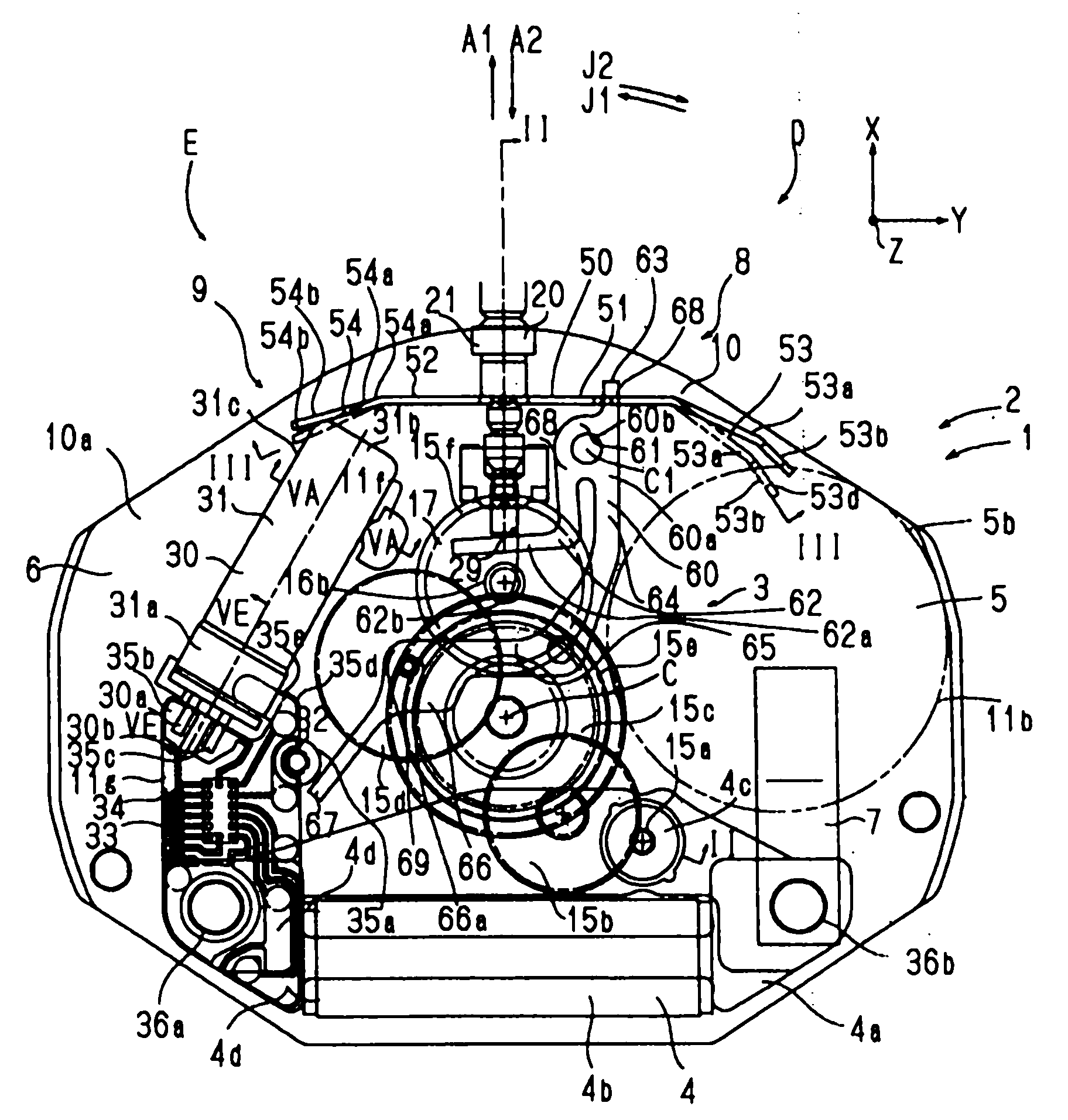
图1是根据本发明一个优选实施例的电子时计的主体部分(处于轮系夹板已被移开的状态)的说明性平面图,其具有作为根据本发明一个优选实施例的馈电件的板簧结构;FIG. 1 is an explanatory plan view of a main body portion (in a state where a wheel train bridge has been removed) of an electronic timepiece according to a preferred embodiment of the present invention, which has a plate as a feed member according to a preferred embodiment of the present invention. Spring structure;
图2是沿着图1中的线II-II的说明性剖视图;FIG. 2 is an explanatory sectional view along line II-II in FIG. 1;
图3显示了板簧结构的设置,图3A是沿着图1中的线IIIA-IIIA的说明性剖视图,图3B是沿着图3A中的线IIIB-IIIB看去的那一部分的说明性视图,图3C是沿着图3A中的线IIIC-IIIC的说明性剖视图,而图3D是图3C的修改示例的类似于图3C的说明性剖视图;Fig. 3 shows the arrangement of the leaf spring structure, Fig. 3A is an explanatory sectional view along line IIIA-IIIA in Fig. 1, Fig. 3B is an explanatory view of the part seen along line IIIB-IIIB in Fig. 3A , FIG. 3C is an explanatory cross-sectional view along line IIIC-IIIC in FIG. 3A , and FIG. 3D is an explanatory cross-sectional view similar to FIG. 3C of a modified example of FIG. 3C;
图4是图1所示板簧结构的说明性透视图;Figure 4 is an explanatory perspective view of the leaf spring structure shown in Figure 1;
图5显示了支撑图1所示石英振荡器壳体的状态,图5A是沿着图1中的线VA-VA的说明性剖视图,图5B是图5A的修改示例的类似于图5A的说明性剖视图,图5C是图5A的另一修改示例的类似于图5A的说明性剖视图,图5D是图5A的又一修改示例的类似于图5A的说明性剖视图,而图5E是沿着图1中的线VE-VE的说明性剖视图;Fig. 5 shows the state of supporting the quartz oscillator case shown in Fig. 1, Fig. 5A is an explanatory sectional view along the line VA-VA in Fig. 1, and Fig. 5B is an illustration similar to Fig. 5A of a modified example of Fig. 5A 5C is an explanatory cross-sectional view similar to FIG. 5A of another modified example of FIG. 5A, FIG. 5D is an explanatory cross-sectional view similar to FIG. 5A of another modified example of FIG. 5A, and FIG. Illustrative cross-sectional view of line VE-VE in 1;
图6是在图1所示电子时计处于非复位状态时的说明性平面图;Fig. 6 is an explanatory plan view when the electronic timepiece shown in Fig. 1 is in a non-reset state;
图7是在图1所示电子时计处于复位状态时的说明性平面图;和7 is an explanatory plan view when the electronic timepiece shown in FIG. 1 is in a reset state; and
图8显示了图1所示电子时计的修改示例,图8A是显示了省略轮系等的状态的类似于图1的说明性平面图,而图8B是沿着图8A中的线VIIIB-VIIIB的说明性剖视图。FIG. 8 shows a modification example of the electronic timepiece shown in FIG. 1, FIG. 8A is an explanatory plan view similar to FIG. 1 showing a state in which a wheel train etc. is omitted, and FIG. 8B is along the line VIIIB-VIIIB in FIG. 8A Illustrative cutaway view of .
具体实施方式Detailed ways
下面将基于附图中所示的一个优选实施例来解释本发明的一个优选实施例。A preferred embodiment of the present invention will be explained below based on a preferred embodiment shown in the drawings.
电子时计1的时计主体2设有构成了机器外壳的主板10。在下文中为了简化说明,采用了固定在主板10上的三维坐标系统。这里,X方向由上条柄轴20的图示方向A1构成(3点钟一侧),Y方向由图1中的右边方向构成(12点钟一侧),而Z方向由垂直于图面的图面深度方向构成。Z方向与具有表盘12(参见图2)的一侧相一致。这里,XY平面平行于时计主体2的正面,而Z轴的方向是垂直于时计主体2的正面的方向。在图1和图2中,标号C是与时计主体2的轮系机构3相连的时间显示指针13(即时针13a、分针13b和秒针13c)的旋转中心轴线。在这里,时计主体2包括时计1中的除表壳外部等以外的那一部分。The
主板10设有凹部和突起部,以及适合于布置和支撑各种时计元件的表面形状,这些时计元件定位在主板10的-Z侧表面10a的相应位置处。主板10具有侧壁11(图2),其具有位于3点钟一侧位置的上条柄轴引导孔11a,主板10还设有突出式地设于-Z侧表面10a上的石英振荡器壳体(石英罐)接受用突起部11f和柔性电路板安装用突起部11g,以及形成于表面10a处的离合轮接受用凹部11h和电池容纳用凹部11b,其中凹部11h和凹部11b的一部分圆周壁由侧壁11等来限定。如下参见图5E所示,柔性电路板安装用突起部11g设有石英振荡器壳体(石英罐)端面接受用侧壁部分11c。另外,在主板10的表面10a中,当从中心轴线C看去时在时针为大约5点钟的方向上嵌有复位销32。复位销32的位置可以是与下述电路板34的布置和形状等相关的其它位置。The
除了位于基端侧上的大直径轴部分21以外,穿过主板10的上条柄轴引导孔11a的上条柄轴20还设有位于前端处的方柱形接合轴部分22、位于中间的柱形中等直径轴部分23、位于轴部分22,23之间的柱形小直径轴部分24,以及在A1,A2方向上的两侧由小直径轴部分25,26来限定的算盘珠状部分27,并且装配在离合轮28中。离合轮28具有位于基端侧的中等直径孔部分,以及位于前端(深度上)侧的方柱形孔部分,该离合轮28设在离合轮接受用凹部11h中,并装配在上条柄轴20上且位于轴部分22,24,23之间。当上条柄轴20沿A2方向被推动而处于0级位置(正常位置)中时,离合轮28的中等直径孔部分和方柱形孔部分可旋转地分别配合在上条柄轴20的中等直径轴部分23和小直径轴部分24上。另一方面,在上条柄轴20沿A1方向被拔出一级而处在第1级位置(拔出位置)中时,离合轮28的方柱形孔部分与位于上条柄轴20前端的方柱形接合轴部分22相接合,并使离合轮28随上条柄轴20在B方向上的旋转而旋转。离合轮28在前端处的齿轮部分28a处与第八齿轮15f啮合。In addition to the large-
如从图1和2中所理解的那样,轮系机构3包括定位在主板10和轮系夹板14的一部分之间的顶侧轮系15,以及定位在主板10的+Z侧上的底侧轮系16,其中轮系夹板14设置在离主板10在-Z方向上有一定间隙之处。轮系夹板14可被认为是机器外壳中的类似于主板10的一部分。顶侧轮系15包括第六齿轮及小齿轮15a、第五齿轮及小齿轮15b、第四齿轮及小齿轮(秒齿轮)15c、第三齿轮及小齿轮15d、第二齿轮及小齿轮(分齿轮)15e以及第八齿轮15f,而底侧轮系16包含小时齿轮(时齿轮)16a和第八小齿轮16b。第八齿轮及小齿轮(分齿轮)的轴或杆17在Z方向上延伸并穿过主板10,第八齿轮15f设于顶侧轮系15的侧面,而第八小齿轮16b设于底侧轮系16的侧面。第三齿轮及小齿轮15d的邻近主板10的轴部装配在下述复位杆60的支承孔66a中。As can be understood from FIGS. 1 and 2 , the
在图1中,在主板10的表面10a内的与上条柄轴20相反一侧的位置即在9点钟一侧的位置中设置了在Y方向上为狭长的电动机4。在图1中,在上条柄轴20和电动机4的右边,将钮扣式电池5设置在限定了部分圆周壁的电池容纳用凹部11b中。另外在图1中,在上条柄轴20和电动机4的左边设置了电路块6和石英振荡器30,其中电路块6包含有安装了时计用IC(集成电路)33的柔性电路板34。根据需要,也可将除IC 33之外的电路部分安装在板34上。In FIG. 1 , a
电动机4包含定子4a、线圈组件4b和转子4c,在转子4c的轴上形成了构成第六齿轮及小齿轮15a的转子小齿轮。电动机4的线圈组件4b通过绕组的延伸部分4d而与柔性电路板34电连接。The
标号36a,36b表示用于将定子4a和线圈组件4b机械地连接在一起的连接部。电路板34在连接部36a的位置处固定在电动机4上,而电池负极端子7在连接部36b的位置处固定在电动机4上。连接部36a,36b在其中心具有孔,从主板10上突出来的突起部可装配到这些孔中并与之热密封,因此电动机4和电路板34等作为一个整体固定在主板10上。电池负极端子7在电池5的+Z侧沿着主板10的表面10a延伸,并与安装在主板10的表面10a上的电池5的端面处的负电极5a(图3A)相接触。电池负极端子7通过电动机4(例如与定子部件4a和线圈组件4b的绕组绝缘的绕组铁芯等)而与电路板34电连接,以便为电路板34提供电池5的负电势。也就是说,电动机4部件的导电部分本身构成了与电池负极端子7协同工作的电源负极侧上的馈电线路。
电动机4的转子4c的轴部分中的-Z侧端部由轮系夹板14可旋转地支撑。电动机4的大直径线圈组件4b在-Z方向上突出来,并可宽松地装配在轮系夹板14的相应凹槽或孔(未示出)中,或者可由轮系夹板14固定住。类似地,在-Z方向上具有很高高度的电池5也宽松地装配在轮系夹板14的相应电池连接和分离用孔(未示出)中。在假定电池5的使用处于寿命范围内的情况下,电池5受到轮系夹板14的压力作用。The −Z side end portion of the shaft portion of the
在电路块6的柔性电路板34的+Z侧表面中的时计主体2的中心侧的侧边上,形成了复位销连接用导电盘部35a,并且当将柔性电路板34安装在实际上与所示示例中的板34具有相同平面形状的主板突起部11g上时,导电盘部35a正好与复位销32的-Z侧端面(顶面)形成接触。自然,只要能以所需的稳定性支撑柔性电路板34,突起部11g的形状就可以不同于柔性电路板34的形状。另外,在连接了轮系夹板14的状态下,轮系夹板14将电路板34的导电盘部35a压到复位销32的顶面上。然而,复位销32和电路板34之间的电连接可通过不同的方式来实现。On the side of the center side of the timepiece
在电路块6中还形成了导电图案35b,35c,35d,并且导电图案35d与连接端子片部35e相连。导电图案35d与时计用IC 33的电压源(电动势)Vdd的供电端子相连,而导电图案35b,35c则与石英振荡器30的端子相连。石英振荡器30的一对连接销或连接端子部30a,30b通过焊接而电连接并固定在导电图案35b,35c上。在其底端处电连接在导电图案35d上的连接端子片部35e沿着主板10的表面10a延伸,并与导电罐圆周面中的+Z侧部分相接触,即与石英罐31的底端部分31a相接触,其中石英罐作为安装在主板10的表面10a上的石英振荡器30的壳体。另外,石英振荡器主体31的基部侧端面31d与主板10的柔性电路板安装用突起部11g的石英振荡器壳体(石英罐)端面接受用侧壁部分(侧面部分)11c形成接触(图5E)。
轮系夹板14形成有作为接合部的凹槽18(图2),并且在凹槽18中锁定了由金属制成的板簧结构50。除了图1和图2之外,如图3和图4中所示,板簧结构50的正面或主表面垂直于XY平面。也就是说,相对于板簧结构50的各个部分的正面的法线都处于平行于XY平面的面上,而与该正面的方向无关。The
如从图1、图3和图4中所理解的那样,板簧结构50包括主体部分51,其大致在Y方向上沿着时计主体2延伸。板簧主体部分51设有在Y方向上延伸的中心部分52、电池正极接触端子部分53,以及石英罐接触端子部分54,其中电池正极接触端子部分53在相对于中心部分52成钝角的倾斜方向上从中心部分52的+Y向端部延伸到-X侧,并且其前端与构成为电池5的正极5b的一部分的电池5的圆周面保持弹性压力接触,而石英罐接触端子部分54在相对于中心部分52成钝角的倾斜方向上从中心部分52的-Y向端部延伸到-X侧,并且其前端与构成石英振荡器壳体的石英罐31的前端部分31b的侧边31c保持弹性压力接触。板簧结构50包括不锈钢合金板,其厚度例如约为0.15-0.2mm。当然,厚度和材料可以有所不同。As understood from FIGS. 1 , 3 and 4 , the
电池正极接触端子部分53包括在相对于中心部分52成钝角的倾斜方向上从中心部分52的+Y向端部延伸到-X侧的倾斜臂部分53a,以及以钝角倾斜地从倾斜臂部分53a的前端延伸到-X侧的电池正极接触部分53b,并且通过电池正极接触部分53b的前端部分与电池正极5b保持压力接触。接触部分53b相对于中心部分52的折弯角整体上小于90度。根据该示例,中心部分53在+Y向端部的附近处在Z方向上加宽,并且电池正极接触端子部分53的-Z侧上的侧边53c上局部地凹入。另外,通过提供在-Z方向上抬起且从该抬起端中向前笔直延伸的前端部分53d,电池正极接触端子部分53的前端中的接触部分53b就可以保证电池正极5b具有较宽的接触区域(图3A)。The battery positive
石英罐接触端子部分54设有窄臂部分54a以及在臂部分54a的前端部分中沿Z方向在宽度上形成的石英罐接触部分54b,并且在接触部分54b处与石英罐31的前端部分31b的侧边31c保持压力接触。The quartz can contact
因此,板簧结构50用作电池正极端子,其经由接触端子片部35e和导电图案35d而直接将电池5的正极5b的电压(电动势)提供给电源端子IC 33,连接端子片部35e和导电图案35d通过在电池正极接触端子部分53处与电池5的正极5b相接触并且在石英罐接触端子部分54处与石英罐31相接触而构成了供电线路。在上述情况中,馈电机构9由板簧结构50和连接端子片部35e构成。Therefore, the
在这种情况下,石英罐31本身用作供电路径,因此与通过电池正极端子将电池5的正极5b和电路板34的电源端子35d直接相连的情况相比,板簧结构50的长度实际上被缩短了石英罐31长度的量。另外,当要在具有轮系的轮系机构部分3的位置处保证电池正极端子的路径时不仅会降低各种零件的设计自由度,而且必须以复杂的平面形状或复杂的折弯形状来构造电池正极端子,因此,在这种情况下,可以相对简单的形状来构造板簧结构50。In this case, the quartz can 31 itself is used as a power supply path, so the length of the
如图3所示,板簧结构50在中心部分52的中心区域52a处装配在轮系夹板14的接合部18的突起部18a的凹槽18b中(图3A和3C),并在突起部52b处装配在轮系夹板14的孔部分18c中(图3A和3B),其中该突起部52b形成于中心部分52的-Z侧的侧边上。作为如图3C所示地在轮系夹板14的突起部18a处形成用于插入板簧结构50的凹槽18b的替代,可通过在轮系夹板14处形成Z字形的多个突起部18d,18e,18f以形成狭窄的直线路径,并且将板簧结构50的一部分(如中心部分52)插入到突起部18d,18e,18f之间以穿过突起部18d,18e,18f,就可以支撑板簧结构50。这些突起部可由能够如图3D所示地与板簧结构50形成线接触(在图3D的平面内为线接触)的截面形状构成,或者可由与侧壁或突出部18a形成面接触而构成了图3C所示的凹槽18b(在图3C的平面内为线接触)的形状构成。如图3A、3C和3D所示地支撑板簧结构50可通过主板10代替轮系夹板14来实现,或者通过轮系夹板14和主板10这两者来实现。突起部18d,18e,18f可由金属制成的销构成,它们从轮系夹板14或主板10中伸出来,代替形成了轮系夹板14或主板10的基体材料的树脂件。板簧结构50可宽松地装配在凹槽部分18b或突起部18d,18e,18f中,或者实际上由它们以无间隙的方式支撑。As shown in FIG. 3, the
板簧结构50由在Y方向上延伸并且在Z方向上整体具有一定宽度的板簧构成,因此可减少在XY平面上所占用的面积。另外,实际上仅通过将凹槽部18b的侧壁锁定到与电池5和石英振荡器罐31形成压力接触而构成支点来固定两端插入到凹槽部18b等中的端子部分53,54,因此不需要诸如旋拧和填密等固定结构,还可将用于固定所需的空间抑制到最低限制。The
板簧结构50还包括从+Z侧的侧边部分中突出来的复位杆偏动弹簧部分56和上条柄轴接合弹簧部分57。上条柄轴接合弹簧部分57包括沿+Z方向从主体部分51中延伸出来的基面臂部分57a、沿+Y方向从基面臂部分57a的延伸端中延伸出来的前端侧臂部分57b,以及从臂部分57b的前端中延伸出来的圆弧形接合部57c,该上条柄轴接合弹簧部分57在圆弧形接合部57c处与上条柄轴20的算盘珠状部分27附近的小直径部分25或26弹性地接合。The
如从图1和图3中所理解的那样,板簧结构50通过在中心部分52处与轮系夹板14的接合部18相接合而受到轮系夹板14的支撑,设于+Y向端部中的电池正极接触端子部分53在D方向上与电池5的正极5b的圆周面保持弹性压力接触,而设于-Y向端部中的石英罐接触端子部分54在E方向上与石英罐31的前端部分31b的侧边31c保持弹性压力接触,该侧边31c由主板10的石英振荡器壳体接受用突起部11f和石英振荡器壳体(石英罐)接受用侧壁部分(侧面部分)11c来支撑。因此,板簧结构50通过以轮系夹板14的接合部18作为支点而弹性地压下电池5和石英振荡器30,因此可同时且稳定地定位和固定住尺寸比其它部件更大且安装稳定性可能较差的电池5和石英振荡器30。另外,由于板簧结构50在其一端处在较大接触压力下与电池5接触,并且在其另一端处在较大接触压力下与石英振荡器30的石英罐31接触,因此可以确定地将电池5的正电势传递给石英罐31。而且,石英罐31通过接触端子片部35e和导电图案35d而与电路块6的IC 33的电源电压供给端子相连,因此可以直接使用石英振荡器30的壳体即石英罐31来供给电源电压。由于石英振荡器壳体部分或石英罐31在电子时计1的主体部分2中占据较大的体积或面积,因此可以使电池正极端子的长度最小化。As can be understood from FIGS. 1 and 3 , the
另外,在上条柄轴接合弹簧部分57的圆弧形接合部57c中,板簧结构50通过与上条柄轴20的算盘珠状部分27两侧上的小直径部分25,26相接合而对上条柄轴20施加F1方向上的弹性作用力,因此可以在没有A1,A2方向上的位置偏移的条件下稳定地和弹性地保持住通过小直径部分25或26与弹簧部分57弹性接合的上条柄轴20,从而使上条柄轴20定位。另外,由于弹簧部分57和小直径部分25或26的接合是弹性接合,例如当上条柄轴20处于0级位置且弹簧部分57的圆弧形接合部57c与上条柄轴20的小直径部分25相接合时,在沿A1方向拔出上条柄轴20的情况下,算盘珠状部分27便通过使弹簧部分57的圆弧形接合部57c弹性变形而在A1方向上运动,从而通过直径大于小直径部分25的算盘珠状部分27而在F2方向上下压。当算盘珠状部分27在A1方向上穿过弹簧部分57时,弹簧部分57的圆弧形接合部57c便通过弹性回复力而再次在F1方向上发生变形,并且装配在小直径部分26上。这样,当在A1方向上拔出上条柄轴20时,板簧结构50的弹簧部分57便与算盘珠状部分27协同操作,从而给出卡嗒声的感觉。同样,当在A2方向上将上条柄轴20从上条柄轴第1级推动到上条柄轴第0级时,弹簧部分57的接合部57c变形到允许从小直径部分26过渡到算盘珠状部分27的最大直径部分,之后装配在小直径部分25上,因此可以获得类似的卡嗒声感觉。In addition, in the arc-shaped
另外,在如上所述地来支撑弹簧部分57的情况下,板簧结构50不仅受到轮系夹板14的接合部18的固定作用,而且通过两端的弹簧部分53,54而受到电池5和石英罐31的支撑,其属于在两端部分53,54处弹性地推挤电池5和石英罐31的反作用,因此就可在稳定保持的状态下稳定位上条柄轴20的支撑。另外,为了避免上条柄轴接合弹簧部分57的臂部分57a,57b在Y方向上有明显的变形,可以在臂部分57a,57b的+Y侧和-Y侧上形成限制壁部分,以便通过它们之间的间隙来插入臂部分57a,57b。该限制壁部分可以是接合壁18等的一部分。In addition, in the case of supporting the
另外,如果需要的话,主板10的表面10a可以形成在-Z方向上伸出的突起部,板簧结构50的中心部分52的+Z侧上的侧边部分52d(图3)可由该突起部来支撑。在这种情况下,可以稳定地防止中心部分52在+Z方向上的位移,因而弹簧部分57可以稳定地提供卡嗒式的感觉。In addition, if necessary, the
电子时计1还设有构成了复位杆主体部分的复位杆60。根据该示例,复位杆60设有由具有整体上如海马形状的冲压金属板件构成的板状部分60a,以及用于在中心部分处围绕旋转中心轴线C1相对于主板10旋转式支撑板状部分60a的轴部60b。轴部60b可旋转地支撑在主板10的支承孔内,或者板状部分60a可相对于轴部60b旋转。轴部60b还可由轮系夹板14支撑,或者由轮系夹板14代替主板10来支撑。The
复位杆板状部分60a包括:L形臂部分62,其从延伸到包含有旋转中心轴线C1的区域中的中心毂部或宽部61延伸到上条柄轴20的前端;弹簧接受部或接合突起部63,其沿X方向从毂部61中突出并与弹簧部分56相接合;大致沿-X方向从毂部61中延伸出来的上下方向上的臂部分64;大致沿-Y方向从上下方向的臂部分64延伸端中稍微倾斜地延伸同时避开电池5的横向臂部分65;形成于臂部分65的前端处的用于支承第三齿轮及小齿轮的宽部或毂部66;以及从毂部66中倾斜地延伸到复位销32的位置处的复位端部67。以上毂部61、L形臂部分62和接合突起部63构成了输入侧杆部68,臂部分64,65,67和毂部66构成了输出侧杆部69。另外,以上复位杆单元8由复位杆60以及板簧结构50的弹簧部分56构成。The return lever plate portion 60a includes: an L-shaped
在上条柄轴20在A2方向上被推挤而处于上条柄轴第0级P0中的情况下,在A2方向上从上条柄轴20的前端面29推动复位杆60的L形臂部分62的前端侧上的位置检测臂部分62a的侧边62b。虽然为了避免作用在上条柄轴20上的A1方向上的反作用力过大而使L形臂部分62通常能略微偏转,但是其具有远高于板簧结构50的复位杆偏动弹簧部分56的刚性,并且将L形臂部分62与弹簧部分56相比,L形臂部分62可基本上被认为是刚性体。With the winding
当上条柄轴20在A2方向上被推挤而处于上条柄轴第0级P0中时,复位杆60的弹簧接受部或接合突起部63沿-Y方向相对于板簧结构50的复位杆偏动弹簧部分56的前端部分56a的+Y侧上的侧边56b被推压,从而使偏动弹簧部分56发生弹性变形,因而就沿G1方向(图3中的实线)移动了复位杆偏动弹簧部分56的前端部分56a。Return of the spring receiving portion or engaging
因此,当上条柄轴20处于上条柄轴第0级中时,如图6所示,复位杆60处于非复位位置H1。也就是说,在上条柄轴20处于上条柄轴第0级的情况下,在上条柄轴20的前端面29所施加的A2方向上的压力作用下,输入侧杆部68通过在J1方向上的枢轴转动而沿G1方向推压板簧结构50的弹簧部分。复位杆60的输出侧杆部69也在J1方向上枢轴转动,并且复位端部67处于其前端侧边67a与复位销32分离的非复位位置K1。另外,在复位杆60处于非复位位置H1时,第三齿轮及小齿轮支撑部66a处于接合位置L1,并且第三齿轮及小齿轮15d与第二齿轮及小齿轮15e啮合,从而将第四齿轮及小齿轮15c的旋转传递到第二齿轮及小齿轮15e上。Therefore, when the winding
另一方面,如图7所示,上条柄轴20在A1方向上被拔出,并且处于上条柄轴第1级位置P1时,那么上条柄轴20的前端面29在A1方向上运动,并且与复位杆60的L形臂部分62的位置检测臂部分62a的侧边62b分离。根据释放使输入侧杆部68在J1方向上的枢轴转动的偏移作用力,通过板簧结构50的弹簧部分56作用在突起部63上的G2方向上的弹性回复力,就可以使输入侧杆部68围绕中心轴线C1沿J2方向枢轴转动。因此,输出侧杆部69也在J2方向上枢轴转动,并将复位端部67在其前端的前端侧边部分67a处推动到复位销32上。也就是说,当在A1方向上拔出上条柄轴20并使其处于上条柄轴的第1级位置P1时,复位杆60将处于复位位置H2,并且复位端部67被设置到其与复位销32形成接触的复位位置K2。结果,从电路块6至电动机4的驱动信号供给终止,电动机4停止旋转,秒针13c停止旋转。另外,当复位杆60处于复位位置K2时,第三齿轮及小齿轮支撑部分66a处于非接合位置L2,第三齿轮及小齿轮15d与第二齿轮及小齿轮15e之间的相互啮合被释放,并且第二齿轮及小齿轮(分齿轮)15e的旋转无法传递到第四齿轮及小齿轮(秒齿轮)15c上。另外,通过使第三齿轮及小齿轮支撑部分66a移动来代替释放相互间啮合的第三齿轮及小齿轮15d与第二齿轮及小齿轮15e,可以释放第三齿轮及小齿轮15d与第四齿轮及小齿轮15c之间的相互啮合。On the other hand, as shown in FIG. 7 , when the winding
在第三齿轮及小齿轮15d与第二齿轮及小齿轮15e之间的相互啮合被释放时,即使用于指针旋转的上条柄轴20的旋转通过分齿轮17而可从离合轮28传递到小时齿轮(时齿轮)16a与第二齿轮及小齿轮(分齿轮)15e上,但是由于旋转没有传递到第四齿轮及小齿轮(秒齿轮)15c上,因此分针13b和时针13a的调整可在不停止秒针13c的状态下进行。When the intermeshing between the third gear and pinion 15d and the second gear and
另外,作为仅用如图5A所示的主板10的石英振荡器壳体接受用突起部11f来支撑石英振荡器壳体(石英罐)31的侧面的替代,如图5B所示,也可在轮系夹板14处形成类似于突起部11f的突起部14a,并且可由该突起部14a来支撑石英振荡器壳体31的侧面。例如,当板簧结构50的Z方向上的位置设置在主板10的表面10a上的离相邻表面部分比较远时,石英罐31就可通过这种方式的支撑而被容易地固定住。另外,如图5D所示,轮系夹板14可设有屋檐形接受部73,石英罐31的侧面可由该屋檐形接受部73来有效地支撑。另外,为了甚至在板簧50未施加压力的情况下也能够将石英振荡器主体31稳定地安装在主板10的石英振荡器壳体接受用突起部11f的附近,如图5C所示,与石英振荡器壳体接受用突起部11f相对的侧壁部分11d还可形成为具有可将振荡器主体31安装在主板10的表面10a上的凹部。In addition, instead of supporting the side surface of the crystal oscillator case (quartz tank) 31 only with the crystal oscillator case receiving protrusion 11f of the
另外,只要板簧结构可在石英罐接触端子部分和电池正极接触端子部分处与石英罐31和电池5的正极5b形成压力接触,那么板簧结构的形状就可以有所不同。图8显示了这样一种改进示例。在图8所示的改进示例中,与图1中所示类似的构件、部分或元件采用相同的标号,而有所改动的部分则在相同标号之后添加了字符W。In addition, the shape of the leaf spring structure may vary as long as it can come into pressure contact with the quartz can 31 and the
根据图8所示的电子时计1W的板簧结构50W,石英罐接触端子部分54W显著地折叠而相对于中心部分52弯曲,其前端处的接触部分54bW被压到石英罐31上。另外,板簧结构50W由嵌入在机器框架10或14中的中心部分52的石英罐接触端子部分54W附近处的销71,72来支撑。根据该示例,在接触端子部分54W,53的端部处与石英罐31和电池5形成压力接触的状态下,销72用作支点。销71,72的位置和数量可以变化。According to the
另外,根据图8所示的时计1W,从图8A和8B中可以看到,轮系夹板14设有屋檐形接受部73,石英罐31的侧面可由该屋檐形接受部73来支撑。另外,图8B对应于图5D。In addition, according to the timepiece 1W shown in FIG. 8, as can be seen from FIGS. 8A and 8B, the
在如上构造的电子时计1W中很明显,板簧结构50W可起到与图1等所示的板簧结构50相似的功能。板簧结构50W可以设置复位杆偏动弹簧部分56或上条柄轴接触弹簧部分57,也可以不设置它们。As is apparent in the electronic timepiece 1W constructed as above, the
Claims (6)
Applications Claiming Priority (2)
| Application Number | Priority Date | Filing Date | Title |
|---|---|---|---|
| JP2004380861 | 2004-12-28 | ||
| JP2004380861A JP2006184239A (en) | 2004-12-28 | 2004-12-28 | Power feeding mechanism and electronic timepiece having the same |
Publications (1)
| Publication Number | Publication Date |
|---|---|
| CN1801005A true CN1801005A (en) | 2006-07-12 |
Family
ID=36611339
Family Applications (1)
| Application Number | Title | Priority Date | Filing Date |
|---|---|---|---|
| CN200510137855.XA Pending CN1801005A (en) | 2004-12-28 | 2005-12-28 | Current feed construct and electronic hour meter with same |
Country Status (4)
| Country | Link |
|---|---|
| US (1) | US20060140059A1 (en) |
| JP (1) | JP2006184239A (en) |
| CN (1) | CN1801005A (en) |
| SG (1) | SG123773A1 (en) |
Families Citing this family (2)
| Publication number | Priority date | Publication date | Assignee | Title |
|---|---|---|---|---|
| JP2006184237A (en) * | 2004-12-28 | 2006-07-13 | Seiko Instruments Inc | Battery electrode terminal member and electronic timepiece having the same |
| US12517472B2 (en) * | 2021-02-26 | 2026-01-06 | Casio Computer Co., Ltd. | Electrode terminal, module and watch |
Family Cites Families (10)
| Publication number | Priority date | Publication date | Assignee | Title |
|---|---|---|---|---|
| US4435088A (en) * | 1982-08-09 | 1984-03-06 | Timex Corporation | Battery switch plate for a timepiece |
| US5416752A (en) * | 1987-07-21 | 1995-05-16 | Seiko Epson Corporation | Timepiece |
| US5446703A (en) * | 1994-12-12 | 1995-08-29 | Timex Corporation | Analog timepiece movement |
| JP4021218B2 (en) * | 2001-04-24 | 2007-12-12 | セイコーエプソン株式会社 | Electronic clock |
| JP2002341060A (en) * | 2001-05-11 | 2002-11-27 | Seiko Instruments Inc | Composite electric component, ground plate structure, and electronic timepiece using the same |
| JP3594021B2 (en) * | 2002-03-27 | 2004-11-24 | セイコーエプソン株式会社 | Electronic clock |
| JP2006184240A (en) * | 2004-12-28 | 2006-07-13 | Seiko Instruments Inc | Plate-like holding structure and electronic timepiece having the same |
| JP2006184238A (en) * | 2004-12-28 | 2006-07-13 | Seiko Instruments Inc | Reset lever device and electronic timepiece having the same |
| JP2006184237A (en) * | 2004-12-28 | 2006-07-13 | Seiko Instruments Inc | Battery electrode terminal member and electronic timepiece having the same |
| JP2006184236A (en) * | 2004-12-28 | 2006-07-13 | Seiko Instruments Inc | Plate-like structure for winding stem positioning and electronic timepiece having the same |
-
2004
- 2004-12-28 JP JP2004380861A patent/JP2006184239A/en active Pending
-
2005
- 2005-12-21 US US11/314,256 patent/US20060140059A1/en not_active Abandoned
- 2005-12-27 SG SG200508380A patent/SG123773A1/en unknown
- 2005-12-28 CN CN200510137855.XA patent/CN1801005A/en active Pending
Also Published As
| Publication number | Publication date |
|---|---|
| SG123773A1 (en) | 2006-07-26 |
| US20060140059A1 (en) | 2006-06-29 |
| JP2006184239A (en) | 2006-07-13 |
Similar Documents
| Publication | Publication Date | Title |
|---|---|---|
| EP1450477B1 (en) | Piezoelectric actuator, and timepiece and portable unit with piezoelectric actuator | |
| CN1797238B (en) | Battery electrode terminal member and electronic timepiece possessing the same | |
| CN1797240A (en) | Plate-like holding structure and electronic timepiece having the same | |
| US20170373411A1 (en) | Connection device and timepiece | |
| CN1797237A (en) | Reset lever apparatus and electronic timepiece having the same | |
| US20030161219A1 (en) | Timepiece with time correction mechanism | |
| CN1815391A (en) | Winding stem positioning plate-like structural body and electronic timepiece possessing the same | |
| JP4260491B2 (en) | Portable electronic devices and watches | |
| US20060140059A1 (en) | Electricity feeding mechanism and electronic timepiece having the same | |
| TW493112B (en) | Device for electrically connecting an electrical power source and an electronic circuit of a timepiece | |
| JP2024106691A (en) | Terminal boards, switch devices, electronic devices and electronic clocks | |
| JP4265914B2 (en) | Watch switch connection structure | |
| JPH10339783A (en) | Electronic clock | |
| JP4688511B2 (en) | Analog electronic timepiece with reset current conduction structure | |
| JP3571942B2 (en) | Electronic clock | |
| JPH0521118Y2 (en) | ||
| EP3355131A1 (en) | Watch | |
| JP7011498B2 (en) | Clock movement and electronic clock | |
| JP2000261221A (en) | Antenna connection structure of radio communication apparatus | |
| JPS5820949Y2 (en) | electronic clock | |
| JP2003217708A (en) | Clip connector | |
| JP4878172B2 (en) | Electronic clock | |
| JPS6028018Y2 (en) | Watch switch structure | |
| JPH0749432Y2 (en) | Watch parts positioning structure | |
| JPH0625884Y2 (en) | Battery holding structure for battery clock |
Legal Events
| Date | Code | Title | Description |
|---|---|---|---|
| C06 | Publication | ||
| PB01 | Publication | ||
| C02 | Deemed withdrawal of patent application after publication (patent law 2001) | ||
| WD01 | Invention patent application deemed withdrawn after publication |