Background technology
In recent years, proposed on the various projection objects things that are projected the regulation that is presented at screen etc. with ccd video camera shootings such as (cameras) image and according to the photographic images that obtains carry out the zoom adjustment, focus on adjust, the projector of the correction (so-called keystone distortion correction) of the trapezoidal distortion of the image of Projection Display etc.
And, as such projector, can enumerate as the spy opens the described projector of 2004-312690 communique, photographic images analysis be determined that the brightness in the photographic images becomes the peak of peak value, and carry out the projector of keystone distortion correction according to this peak.
As previously mentioned, the peak of the brightness in determining photographic images carries out in the projector of keystone distortion correction etc., when be projector with respect to the projection objects thing be provided with obliquely, when being so-called pitching projection state, because will there be following problem in the reflection direction of the projected light on the projection objects thing.In addition, use brightness value to describe as the value of expression brightness.
The key diagram of the projection state of the projector when Fig. 5 is the existing non-pitching projection of expression.
The PJ of projector shown in Figure 5, be as the adjustment that is used to carry out keystone distortion correction etc. with pattern image comprehensively the image projection of white and can determine to take the projector that the peak that is projected the brightness value in the photographic images that is presented at the image on the screen S c and obtains carries out the keystone distortion correction to screen S c as the projection objects thing.
Wherein, the PJ of projector is arranged on the below not block user's the visual field with respect to screen S c.And, in the projection optical system of the PJ of projector, carry out lens displacements, though make the image of when this is provided with the position and carries out projection Projection Display can be not trapezoidal etc. yet ground distort.Therefore, as shown in Figure 5, depart from downwards with the center of pattern image G by the adjustment of the intersection point (hereinafter referred to as " melatope ") of the optical axis of the optical system of the PJ of projector shown in the thick arrow and screen S c from Projection Display.
In addition, in Fig. 5, owing to be not the pitching projection, the angle (hereinafter referred to as " luffing angle ") of the vertical direction between the optical axis of the optical system of the normal of screen S c and projector PJ inside is 0 degree.
And, in the PJ of projector, near not shown projection optical system, be provided with shoot part CA.This shoot part CA is made of ccd video camera, and it is taken screen S c with the mode in the zone of pattern image G according to the adjustment that comprises Projection Display, and obtains the view data at the photographic images that is made of the RGB data of each pixel.
In addition, in the PJ of projector, automatic exposure adjustment function works.Particularly, in the PJ of projector, in advance the desired value of the average luminance value of both full-pixel in the view data of photographic images is set as exposure target value.And, according to the view data of taking the photographic images that obtains by shoot part CA, calculate the average luminance value of both full-pixel, and in the shutter speed of control shoot part CA, gain, aperture at least 1 is so that the average luminance value of calculating becomes the desired value as the average luminance value of exposure target value.
Wherein, suppose that brightness value gets the value in 0~255 scope, in the PJ of projector, be set at " 50 " as this exposure target value.
The key diagram that briliancy in the projection state of the projector when Fig. 6 (A), (B) are the existing non-pitching projection of expression and the photographic images that obtains under this projection state distributes.
In Fig. 6, (A) be the figure of the projection state shown in the horizontal table diagrammatic sketch 5, (B) be that the curve map that the brightness value of each pixel of position suitable with the horizontal line L1 that comprises melatope shown in Figure 5 in the photographic images distributes is represented on pattern ground.In addition, in Fig. 6 (B), the horizontal position of transverse axis remarked pixel, the longitudinal axis is represented brightness value.
Shown in Fig. 6 (B), the shape that briliancy distributes becomes the position suitable with melatope as the steep chevron of the gradient of peak.This be because, because in the scope of the projected light of the PJ of projector, briliancy in the short more then photographic images of distance between screen S c and the PJ of projector is big more, and owing at this moment do not have the inclination of horizontal direction, so the position suitable with melatope just becomes peak.In addition, because the specular light on the screen S c so brightness value increases sharp on the position suitable with melatope, thereby becomes the steep chevron of the gradient towards the PJ of projector.
Fig. 7 (A), (B) are the key diagrams that the briliancy the projection state of the projector when representing existing pitching projection and the photographic images that obtains under this projection state distributes.
In Fig. 7, (A) be the figure of the projection state when laterally representing the pitching projection, (B) be pattern ground expression with the photographic images that under the projection state of Fig. 7 (A), obtains in comprise the curve map that the brightness value of each pixel of the suitable position of the horizontal line of melatope distributes.In addition, in Fig. 7 (B), because transverse axis is identical with Fig. 6 (B) with the longitudinal axis, so omit explanation.
As mentioned above, in the projection optical system of the PJ of projector, carry out the lens displacement.But, even in the limit that projecting lens etc. is displaced to the lens displacement and the PJ of projector also blocks under user's the situation in the visual field, shown in Fig. 7 (A), the PJ of projector further is provided with downwards, and, be provided with obliquely according to the mode of facing upward with respect to screen S c.In addition, the PJ of projector is provided with luffing angle 10 degree.
In addition, the situation of the exposure target value of setting in the PJ of projector and Fig. 6 similarly is set at " 50 ".
Shown in Fig. 7 (B), same with Fig. 6 (B), brightness value becomes peak value on the position suitable with melatope.But different with 6 (B), the shape that briliancy distributes becomes the indefinite mild chevron of peak.
As mentioned above, in the scope of the projected light of the PJ of projector because the briliancy in the short more then photographic images of distance between screen S c and the PJ of projector is big more, so, with Fig. 6 (B) equally, brightness value becomes peak value on the position suitable with melatope.But, shown in the thick arrow of Fig. 7 (A), under the situation of pitching projection, because the specular light on the screen S c of projected light of this melatope of irradiation is towards the direction that departs from the PJ of projector, so the brightness value of the position suitable with peak is little during than non-pitching projection.Its result, in photographic images, the difference of the brightness value of the position beyond the brightness value of peak and the peak diminishes, thus the shape that briliancy is distributed becomes mild chevron.
In addition, it is big more that luffing angle becomes, and then the specular light of the projected light of irradiation optical axis point is towards the direction that more departs from the PJ of projector, so the shape that briliancy distributes becomes the indefinite milder chevron of peak.
Therefore, in the past under the situation of pitching projection, because the peak that briliancy becomes peak value in the photographic images became indeterminate and can't determine peak accurately, so there is the possibility that to carry out keystone distortion correction etc. exactly.
Embodiment
Below, be used to implement the mode of the best of the present invention by the explanation of following order according to embodiment.
A. embodiment
A1. the summary of projector
The summary of A2 image projection action
A3. the briliancy peak is made clear and is handled and the keystone distortion correcting process
A4. the effect of embodiment
B. variation
A. embodiment
A1. the summary of projector
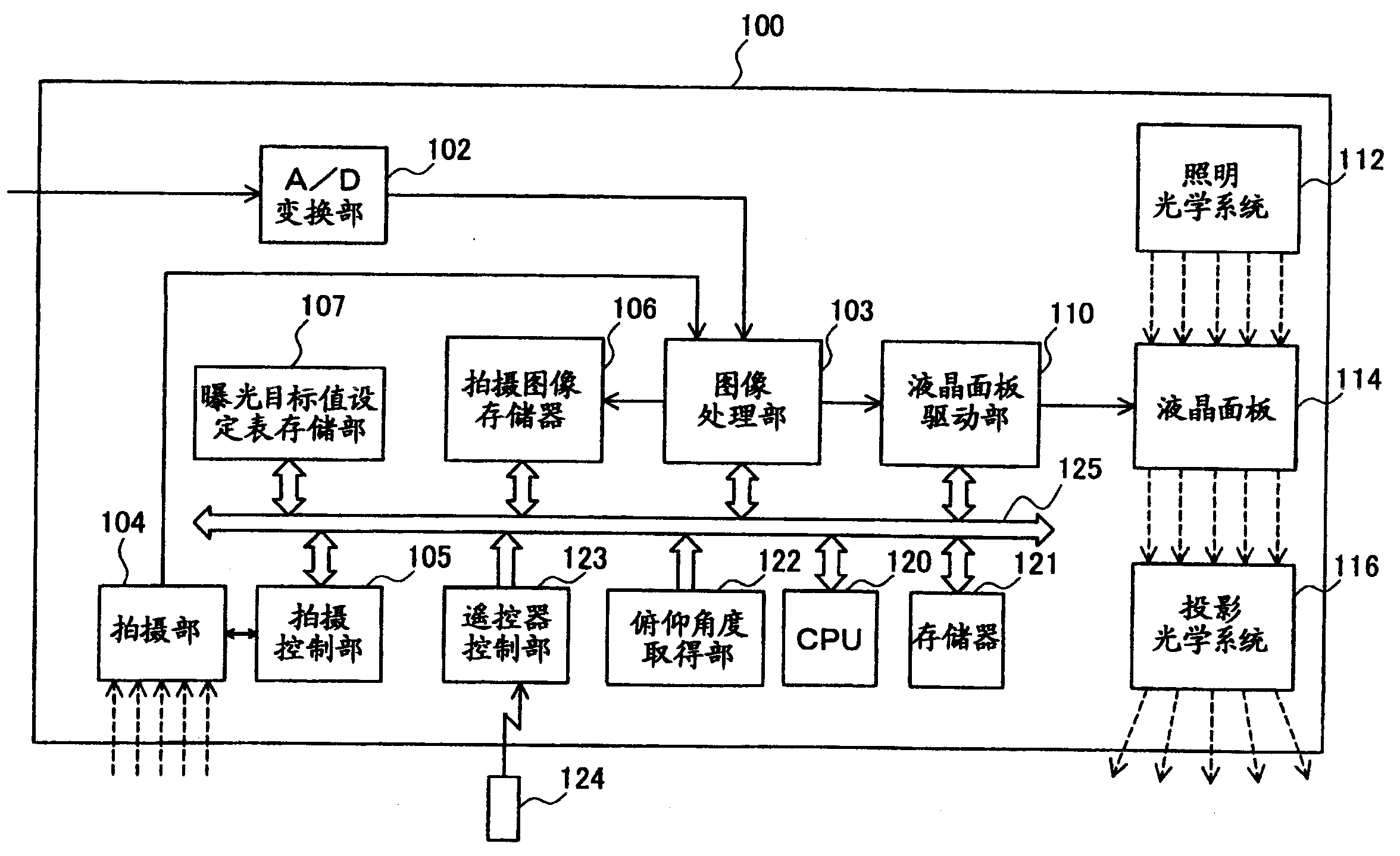
Fig. 1 is the key diagram of summary structure of the projector of expression embodiments of the invention.The existing PJ of projector of this projector 100 and Fig. 5~shown in Figure 7 is same, is to take the projector that the peak that is projected brightness value in image that is presented on the screen and the photographic images that can determine to obtain carries out the keystone distortion correction.
As shown in the figure, projector 100 has A/D transformation component 102, image processing part 103, shoot part 104, shooting control part 105, photographic images storer 106, exposure target value setting table storage part 107, liquid crystal panel drive division 110, CPU120, storer 121, luffing angle obtaining section 122, telepilot control part 123 and telepilot 124.
And then as the inscape of optical system, projector 100 has lamp optical system 112, liquid crystal panel 114 that is made of lamp and reverberator etc. and the projection optical system 116 that is made of projecting lens etc.
CPU120 is connected with telepilot control part 123 by internal bus 125 and image processing part 103, shooting control part 105, photographic images storer 106, exposure target value setting table storage part 107, liquid crystal panel drive division 110, storer 121, luffing angle obtaining section 122.
Shoot part 104 is made of ccd video camera, and is same with the PJ of projector shown in Figure 5, be arranged on projection optical system 116 near.In addition, shoot part 104 can be taken predetermined zone, the exposure adjustment when shooting control part 105 can be controlled in shutter speed in this shoot part 104, gain, the aperture at least 1 and takes.
Luffing angle obtaining section 122 is made of acceleration transducer etc., utilizes this acceleration transducer, can detect the inclination of projector's 100 bodies, and calculate and obtain above-mentioned luffing angle according to detected inclination.
Before projector 100 dispatched from the factory, exposure target value setting table was stored in the exposure target value setting table storage part 107 in advance.
In addition, in the present embodiment, the described control part of above-mentioned CPU120 and claim is suitable with analysis portion, and above-mentioned luffing angle obtaining section 122 is suitable with the described angle information obtaining section of claim.
A2. the summary of image projection action
Below, the conduct image projection action of action usually of projector 100 is described simply.
In Fig. 1, when the user uses a teleswitch 124 indications when beginning to carry out image projection, the indication that telepilot 124 utilizes radio communication to import sends telepilot control part 123 to.Telepilot control part 123 will send CPU120 to from the indication of telepilot 124 by internal bus 125.CPU120 carries out the image projection action according to these indication controls with each the formation portion headed by the image processing part 103.
At first, A/D transformation component 102 input is from the analog picture signal of outputs such as video player, televisor, DVD player or from the analog picture signal of outputs such as personal computer, and these analog picture signals is transformed to data image signal and to image processing part 103 outputs.Also input digital image signal not via A/D transformation component 102.Image processing part 103, the data image signal of adjusting input make the shape of the show state of image, for example contrast, acutance, image etc. become desired state, and to 110 outputs of liquid crystal panel drive division.
Liquid crystal panel drive division 110 is according to the data image signal driving liquid crystal panel 114 of input.Thus, the illumination light that in liquid crystal panel 114, penetrates from lamp optical system 112 according to the image information modulation.Projection optical system 116 is installed in the front of the framework (cabinet) of projector 100, and it will be projected on the not shown screen by the projected light of liquid crystal panel 114 modulation.Thus, image is projected and is presented on the screen.
In addition, in above-mentioned projection optical system 116, similarly carry out the lens displacement with the above-mentioned existing PJ of projector.And when non-pitching projection, projection state is identical with projection state shown in Figure 5.
A3. the briliancy peak is made clear and is handled and the keystone distortion correcting process
Same with shown in Fig. 7 (A), the user below projector 100 is arranged on respect to screen obliquely with luffing angle 10 degree after, when connecting the power supply of projector 100, projector 100 will adjust usefulness pattern image Projection Display on screen.
Particularly, image processing part 103 shown in Figure 1 generates white comprehensively image and is used as the adjustment pattern image, and the image of this generation and the action of above-mentioned image projection similarly are projected and are presented on the screen.
Then, the user uses telepilot shown in Figure 1 124 indications to begin to carry out the keystone distortion correction.At this moment, the indication that this keystone distortion correction begins, the indication that begins with image projection in the action of above-mentioned image projection similarly is transmitted to CPU120 by telepilot control part 123 and internal bus 125.Then, CPU120 before the processing of carrying out the keystone distortion correction, reads and carries out from storer 121 and be used for the program that the briliancy peak is made processing clear.Then, after this program was performed, the briliancy peak that begins to carry out as characteristic of the present invention was made processing clear.
Fig. 2 is the process flow diagram that expression briliancy peak of the present invention is made the step of processing clear.
Make clear when handling when beginning to carry out briliancy peak shown in Figure 2, at first, CPU120 uses luffing angle obtaining section 122 to obtain luffing angle and store (step S202) in the storer 121 into.As mentioned above, when projector 100 was provided with luffing angle 10 degree, angle obtaining section 122 obtained this " 10 degree " and stores in the storer 121.
Then, CPU120 reads the luffing angle of being obtained by luffing angle obtaining section 122 from storer 121, and the desired value when will the exposure target value corresponding with the immediate luffing angle of the luffing angle with reading in the luffing angle put down in writing in the exposure target value setting table in being stored in exposure target value setting table storage part 107 adjusting as exposure described later determines, and is set (step S204) in the shooting control part 105.
Fig. 3 is the key diagram that expression is stored in the exposure target value setting table in the exposure target value setting table storage part 107.
As shown in Figure 3, set in the table, set exposure target value accordingly respectively with 5 degree luffing angle at interval at exposure target value.Wherein, so-called exposure target value, identical with the exposure target value of setting among the above-mentioned existing PJ of projector, be the desired value of the average luminance value of both full-pixel in the photographic images.
In addition, as shown in Figure 3, set in the table at exposure target value, set bigger exposure target value accordingly with bigger luffing angle, its reason describes in the back.
And, as mentioned above, be 10 when spending at luffing angle, the desired value when CPU120 adjusts exposure target value " 60 " as exposure is determined and is set in the shooting control part 105.
Then, shooting control part 105 is exposed and is adjusted the exposure target value of being set by CPU120 to become (step S206).
Particularly, at first, shooting control part 105 control shoot parts 104 are taken and are comprised the screen of the adjustment of Projection Display on screen with pattern image, and store in the photographic images storer 106 by the view data (RGB data) that image processing part 103 will be taken the photographic images that obtains.Then, shooting control part 105 is read the view data that is stored in the photographic images in the photographic images storer 106, and utilizes the formula of calculating of appointment to calculate the brightness value of each pixel according to the view data of reading, thereby calculates the average luminance value of both full-pixel.
Then, adjustments that expose of shutter speed, gain, the aperture of shooting control part 105 control shoot parts 104 makes this average luminance value of calculating become exposure target value by the CPU120 setting.
And shooting control part 105 is carried out the control of calculating of above-mentioned shooting, average luminance value and shutter speed etc. repeatedly, till making the average luminance value of calculating become this exposure target value.
And the result that this exposure is adjusted makes the average luminance value of both full-pixel consistent with exposure target value.Therefore, as mentioned above, when having determined " 60 " as exposure target value, the result of above-mentioned exposure adjustment makes the average luminance value of both full-pixel become 60.
The key diagram that briliancy in the projection state of the projector when Fig. 4 (A), (B) are expression pitching projection of the present invention and the photographic images that obtains under this projection state distributes.
In Fig. 4, owing to being same (A), so omit explanation with Fig. 7 (A).In addition, in Fig. 4, (B) be pattern be illustrated under the projection state of Fig. 4 (A), the brightness value of each pixel of the position suitable with the horizontal line that comprises melatope distributes in the photographic images that obtains after above-mentioned exposure adjustment curve map.In addition, in Fig. 4 (B), because transverse axis is identical with Fig. 7 (B) with the longitudinal axis, so omit its explanation.
In Fig. 4 (B), the briliancy when thick solid line represents that exposure target value is " 60 " distributes, and the briliancy when thin dotted line represents that exposure target value is " 50 " distributes.In addition, distribute identical by the distribution of the briliancy shown in this thin dotted line with the briliancy shown in Fig. 7 (B).
Shown in the thick solid line of Fig. 4 (B), brightness value becomes peak value on the position suitable with melatope.And the shape that the briliancy the when shape that the briliancy when exposure target value is " 60 " distributes is " 50 " with exposure target value distributes is compared, and becomes the steeper chevron of the gradient, and is clearer and more definite thereby peak becomes.
This be because, by above-mentioned exposure adjustment, the brightness value of each pixel when brightness value of each pixel when exposure target value is " 60 " is " 50 " with exposure target value is compared, 1.2 times of average out to, and the difference of the brightness value between each pixel when difference of the brightness value between each pixel when exposure target value is " 60 " is " 50 " with exposure target value is compared, and also is 1.2 times.
In addition, in order to make peak clear and definite by improving exposure target value, can consider in advance the maximal value " 80 " of exposure target value shown in Figure 3 is set at the exposure target value corresponding with all luffing angles, but at luffing angle hour, for example luffing angle is when pitching projection (non-) 0 when spending, the brightness value of each pixel is compared for the brightness value of " 50 " with exposure target value, on average increases to 1.6 times.Its result, brightness value becomes maximal value 255 on the position suitable with melatope, and, on the position suitable, also might become maximal value 255 with its periphery.Therefore, at this moment peak becomes indeterminate.
At this, the reason of setting bigger exposure target value in exposure target value setting table with bigger luffing angle accordingly is described.
When projector was provided with more obliquely with respect to screen, it is bigger that luffing angle becomes, and as mentioned above, the specular light of the projected light of irradiation optical axis point is towards the direction that more departs from projector.Therefore, do not use when of the present invention, the shape that briliancy distributes becomes milder chevron, and is more indeterminate thereby peak becomes.
Therefore, as shown in Figure 3, set in the table at exposure target value, by setting bigger exposure target value accordingly with bigger luffing angle, determine bigger exposure target value under the situation of bigger luffing angle, exposing to adjusting makes it to become this desired value.Its result, even when luffing angle becomes big, the difference of the brightness value between each pixel also becomes clearly, the shape that briliancy is distributed becomes the steep chevron of the gradient, thereby makes peak become clear and definite.
Like this, obtain the value that peak becomes clear and definite under the situation of each luffing angle and set as setting the exposure target value of setting in the table at exposure target value, waiting by experiment in advance.
More than Shuo Ming briliancy peak is made the result of processing clear, and the position that briliancy becomes peak value in photographic images becomes clear and definite.
Secondly, CPU120 reads and carries out the program that is used for determining the correction used in the keystone distortion correcting process from storer 121.Then, CPU120 is according to this program, indicates for shooting control part 105 and controls shoot part 104, makes its shooting be projected the adjustment pattern image of demonstration, and with the image data storage of the photographic images that obtains in photographic images storer 106.Then, CPU120 reads the view data of the photographic images of taking and obtaining from photographic images storer 106, and determines the peak of brightness value according to the view data of reading.
As mentioned above, owing to make processing clear and the briliancy peak is become clearly by the briliancy peak, so CPU120 can determine peak accurately.
Wherein, the peak of brightness value is stored in the storer 121 accordingly in advance with the correction of using in the keystone distortion correcting process.And CPU120 is defined as the employed correction of keystone distortion correction with the correction corresponding with the peak of the brightness value of determining, and reads from storer 121 and pass to image processing part 103.
Then, image processing part 103 carries out keystone distortion correction to adjusting with pattern image adjustment according to the correction of transmitting from CPU120.In addition, image processing part 103 also carries out the keystone distortion correction for the data image signal adjustment of importing from A/D transformation component 102 according to this correction.
In addition, this keystone distortion correction is according to the mode that the trapezoidal distortion of the image of Projection Display is offset, by being trapezoidal the execution with the image correction of projection in advance.And above-mentioned correction is the value of the position on this revised trapezoidal each summit of expression.
And, as mentioned above,, transmit to image processing part 103 so can determine best correction because CPU120 can determine peak accurately.Its result can carry out above-mentioned keystone distortion correction exactly.
A4. the effect of embodiment
As described above, in the exposure target value setting table in being stored in projector 100, set peak accordingly with luffing angle and become clear and definite exposure target value.And CPU120 sets table according to this exposure target value, and the desired value when exposure is adjusted is set in the shooting control part 105, and shooting control part 105 is exposed and adjusted the exposure target value that makes it to become setting.Therefore, because the result of this exposure adjustment makes that peak becomes clearly in photographic images, carry out keystone distortion correction accurately so can determine accurately peak.
In addition, set the exposure target value of setting in the table, set bigger value accordingly with bigger luffing angle at this exposure target value.Therefore, under the situation of bigger luffing angle, expose and adjust so that the mean value of the brightness value of each pixel becomes bigger.Its result even the specular light of the projected light of and irradiation optical axis point bigger at luffing angle when more departing from the direction of projector 100, also can increase the poor of brightness value between each pixel in the photographic images, thereby can make peak become clear and definite.
B. variation
In addition, the invention is not restricted to the foregoing description or embodiment, in the scope that does not break away from aim of the present invention, can implement in every way, for example, can be following distortion.
B1. variation 1
In the above-described embodiments, exposure target value setting table has stored in the projector 100 before dispatching from the factory, but is not limited thereto.For example, also can be after projector 100 to dispatch from the factory, the user will set with personal computer etc. and directly be connected with projector 100, and the exposure target value setting table of oneself making is stored in the exposure target value setting table storage part.
Like this, can use the environment (for example, the projection objects thing that projects image onto beyond the screen is first-class) of projector 100 to set best exposure target value according to reality.
B2. variation 2:
Set in the table at the exposure target value of the foregoing description, as shown in Figure 3, modes with 5 degree luffing angle have at interval been set exposure target value, but are not limited to 5 degree, also can setting less than 5 degree or greater than the mode of the luffing angle of the angle intervals of 5 degree according to 4 degree or 6 degree etc.
In addition, it also can not above-mentioned exposure target value setting table, but luffing angle is waited the formula of calculating that can derive exposure target value of obtaining in advance by experiment as parameter, CPU120 is according to the luffing angle that uses luffing angle obtaining section 122 to obtain, use this to calculate formula and derive exposure target value, thereby be defined as exposing desired value when adjusting.
B3. variation 3
In the above-described embodiments, in projector 100, in order to carry out the keystone distortion correction exactly, carried out the briliancy peak and made processing clear, but the invention is not restricted to the keystone distortion correction.Wait in other image adjustment in zoom adjustment or focusing adjustment, when the peak that uses photographic images is adjusted, also can use the present invention,, can carry out image adjustment accurately by definite peak more accurately by using the present invention.
B4. variation 4
In the above-described embodiments, make peak clear and definite at the situation of pitching projection longitudinally, but also can replace or with this situation combination, under the situation of horizontal deflection projection, use the present invention, thereby make peak clear and definite.
In this case, horizontal inclination (normal of screen and the angle of the horizontal direction between optical axis) at projector, for example on screen to putting on mark in advance with four jiaos of rectangle suitable positions, carry out the zoom adjustment and make 2 summits on 2 summits in left side of image of Projection Display and right side consistent with these marks respectively, and detect according to the zoom amount of separately zoom adjustment.In addition, set table as exposure target value, also can replace luffing angle or with its combination, obtain the exposure target value of the best corresponding by experiment in advance, and set accordingly with horizontal inclination with horizontal inclination.
B5. variation 5
In the above-described embodiments, in the projection optical system 116 of projector 100, carried out the lens displacement, even but under the situation that does not have the lens displacement, also can use the present invention, also can make peak clear and definite in this case.
B6. variation 6
In the above-described embodiments, used the image of comprehensive white as adjusting with pattern image, but to be not limited thereto, for example, also can use the mark of the image of grey scale pattern or performance appointment or logo image etc. with appointment.
B7. variation 7
In the above-described embodiments, used brightness value (Y), but also can replace it and use the some GTG values among R, G, the B or the mean value of these GTG values as the value of expression brightness.
B8. variation 8
In the above-described embodiments, projector 100 is liquid crystal projectors, but also can be DLP projector (DLP is a registered trademark).