CN1819965A - Shock absorbing hitch - Google Patents
Shock absorbing hitch Download PDFInfo
- Publication number
- CN1819965A CN1819965A CNA03826868XA CN03826868A CN1819965A CN 1819965 A CN1819965 A CN 1819965A CN A03826868X A CNA03826868X A CN A03826868XA CN 03826868 A CN03826868 A CN 03826868A CN 1819965 A CN1819965 A CN 1819965A
- Authority
- CN
- China
- Prior art keywords
- biasing
- support member
- elevator system
- tension
- terminal
- Prior art date
- Legal status (The legal status is an assumption and is not a legal conclusion. Google has not performed a legal analysis and makes no representation as to the accuracy of the status listed.)
- Pending
Links
Images



Classifications
-
- B—PERFORMING OPERATIONS; TRANSPORTING
- B66—HOISTING; LIFTING; HAULING
- B66B—ELEVATORS; ESCALATORS OR MOVING WALKWAYS
- B66B7/00—Other common features of elevators
- B66B7/06—Arrangements of ropes or cables
- B66B7/10—Arrangements of ropes or cables for equalising rope or cable tension
-
- B—PERFORMING OPERATIONS; TRANSPORTING
- B66—HOISTING; LIFTING; HAULING
- B66B—ELEVATORS; ESCALATORS OR MOVING WALKWAYS
- B66B7/00—Other common features of elevators
- B66B7/06—Arrangements of ropes or cables
- B66B7/08—Arrangements of ropes or cables for connection to the cars or cages, e.g. couplings
- B66B7/085—Belt termination devices
Landscapes
- Lift-Guide Devices, And Elevator Ropes And Cables (AREA)
- Cage And Drive Apparatuses For Elevators (AREA)
Abstract
Description
技术领域technical field
本发明总体上涉及一种升降机系统。更具体的是,本发明涉及对升降机系统中承载部件上的张力进行控制。The present invention generally relates to an elevator system. More particularly, the present invention relates to controlling tension on load-carrying components in elevator systems.
背景技术Background technique
升降机系统通常包括在井道内反向运动的轿厢和配重。承载部件,如绳索或带子支撑轿厢和配重进行所需的运动。在一些情形下,承载部件上的张力需要控制在理想的限度内,以保证适当的牵引力,并防止在系统部件上产生不希望有的应力。Elevator systems typically include a car and counterweight that travel in opposite directions within a hoistway. Load bearing components such as ropes or straps support the car and counterweight for the required movement. In some cases, the tension on the load bearing components needs to be controlled within desirable limits to ensure proper traction and prevent unwanted stress on system components.
一个示例的情况是,在所谓的轿厢或配重跳跃的过程中,在绳索上会产生不希望有的很大的应力。例如,当配重迅速下降并撞击井道底部附近的保险装置或缓冲装置时,发生轿厢跳跃。即使是在配重已经撞击保险装置或缓冲装置以后,上升的轿厢仍然继续向上移动。当运动轿厢的动能消耗后,由于因轿厢额外的向上运动而造成的绳索松散,使得轿厢再次回落。当轿厢向下移动回来时,在绳索、驱动机和升降机系统的其他支撑结构上会产生很大的应力。当轿厢迅速下降并撞击井道底部附近的保险装置或缓冲装置,或者迅速下降后突然停止时,配重会出现类似的跳跃。An example situation is that during so-called car or counterweight jumps, undesirably large stresses are generated on the ropes. For example, car jumping occurs when the counterweight drops rapidly and hits a safety device or buffer near the bottom of the hoistway. Even after the counterweight has struck the safety device or buffer, the ascending car continues to move upwards. When the kinetic energy of the moving car is exhausted, the car falls back down again due to loosening of the ropes due to the extra upward movement of the car. When the car moves back down, there is a lot of stress on the ropes, drive machine and other supporting structures of the elevator system. A similar jump occurs in the counterweight when the car descends rapidly and hits a safety device or buffer near the bottom of the hoistway, or comes to a sudden stop after descending rapidly.
将轿厢和配重的跳跃最小化的常规方法是使用系紧(tie-down)补偿。有各种不同的已知系紧装置。虽然传统的装置有助于将绳索的松弛减到最小,并防止轿厢或配重跳跃有关的高的动态应力,但它们也不是没有缺点。举个例子,液压系紧装置很昂贵,并且对井道底坑地面有结构要求,这继而增加了成本和人力。此外,这种装置需要的最小底坑深度比很多情况所需或可使用的底坑深度要大。A conventional approach to minimize car and counterweight jumping is to use tie-down compensation. There are various known fastening devices. While conventional arrangements help to minimize rope slack and prevent the high dynamic stresses associated with car or counterweight jumping, they are not without their drawbacks. As an example, hydraulic tie-downs are expensive and have structural requirements on the shaft pit floor, which in turn increases cost and manpower. In addition, such arrangements require a minimum sump depth that is greater than is required or available in many cases.
在依赖于承载绳索或带子的张力的升降机系统中,还需要更好的控制张力。此外,总是需要将与安装和操作升降机系统有关的费用最小化。本发明以一种成本效率的方式处理了发生配重或轿厢跳跃时对承载部件上的张力进行管理的需要。There is also a need for better tension control in elevator systems that rely on the tension of the carrying rope or belt. Furthermore, there is always a need to minimize the costs associated with installing and operating elevator systems. The present invention addresses the need to manage the tension on the load bearing member in the event of counterweight or car jumping in a cost effective manner.
发明内容Contents of the invention
概括的来说,本发明是一种减震联结器装置,该装置在某些情况下,如轿厢或配重跳跃的情况下,吸收至少一部分施加在升降机系统的承载部件上的负荷。In general terms, the present invention is a shock absorbing coupling arrangement that absorbs at least a portion of the loads imposed on load-bearing components of an elevator system under certain conditions, such as car or counterweight jumping conditions.
一种依据本发明设计的示例系统包括轿厢和配重。承载部件支撑轿厢和配重,使得轿厢在一个方向上运动,而配重在相反的方向上运动。终端装置与承载部件的至少一个端部相连接。该终端装置的一部分响应于承载部件(26)上低于选定阈值的张力而克服第一偏压进行移动。该终端装置的一部分响应于超过该阈值的张力而克服第二偏压进行移动。An example system designed in accordance with the present invention includes a car and a counterweight. The load bearing member supports the car and the counterweight so that the car moves in one direction while the counterweight moves in the opposite direction. A terminal device is connected to at least one end of the carrier part. A portion of the terminal device moves against the first bias in response to tension on the carrier member (26) below a selected threshold. A portion of the end device moves against the second bias in response to the tension exceeding the threshold.
在一个例子中,该终端装置包括终端部件和支撑部件。终端部件相应低于阈值的张力而相对于支撑部件移动。当张力超过阈值时,支撑部件与终端部件一起移动。在一个例子中,该终端部件是套筒杆。In one example, the terminal device includes a terminal part and a support part. The terminal member moves relative to the support member in response to a tension below the threshold. When the tension exceeds a threshold, the support part moves together with the terminal part. In one example, the end piece is a sleeve rod.
一个示例系统包括第一偏压部件,其将终端部件的一个端部从支撑部件偏移开。第二偏压部件将支撑部件从升降机系统中的选定结构上的固定表面上偏移开。该终端部件响应升降机系统内承载部件上的正常负荷而克服第一偏压部件的偏压进行移动。当承载部件上的张力超过选定阈值时,支撑部件相应增加的负荷而克服第二偏压部件的偏压进行移动。One example system includes a first biasing member that biases one end of the terminal member away from the support member. The second biasing member biases the support member away from the fixed surface on a selected structure in the elevator system. The terminal member moves against the bias of the first biasing member in response to normal loads on the load bearing member within the elevator system. When the tension on the load bearing member exceeds a selected threshold, the support member moves against the bias of the second biasing member in response to the increased load.
在一个例子中,第一偏压部件包括螺旋弹簧。第二偏压部件包括机械弹簧、空气弹簧、液压致动器或气动致动器中的至少一种。在一个例子中,该第二偏压部件最好被预加负载,使得第二偏压部件的劲度比第一偏压部件的劲度低,但是在承载部件上的张力将螺旋弹簧有效压缩一所需量,该第二偏压部件不允许支撑部件移动。因为第二偏压部件响应承载部件上的张力来移动,故第二偏压部件的工作最好是被动的。In one example, the first biasing member includes a coil spring. The second biasing member includes at least one of a mechanical spring, an air spring, a hydraulic actuator, or a pneumatic actuator. In one example, the second biasing member is preferably preloaded such that the stiffness of the second biasing member is lower than the stiffness of the first biasing member, but tension on the load bearing member effectively compresses the coil spring A desired amount, the second biasing member does not allow the support member to move. The operation of the second biasing member is preferably passive because the second biasing member moves in response to tension on the carrier member.
通过对下面的当前优选实施例的详细叙述,本领域技术人员可以显而易见地得出本发明的各种特征和优点。详细说明所附的附图将在下面简要介绍。Various features and advantages of the present invention will become apparent to those skilled in the art from the following detailed description of the presently preferred embodiments. The drawings that accompany the detailed description are briefly described below.
附图说明Description of drawings
图1示意性地示出了依据本发明的实施例设计的一种示例性升降机系统。Fig. 1 schematically shows an exemplary elevator system designed according to an embodiment of the present invention.
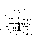
图2示意性地示出了减震联结器的一个示例性实施例,该减震联结器被支撑为与升降机轿厢一起移动。Figure 2 schematically illustrates an exemplary embodiment of a damping coupling supported for movement with an elevator car.
图3是图2中减震联结器实施例的局部剖面图。Fig. 3 is a partial cross-sectional view of the embodiment of the damping coupling in Fig. 2 .
图4用曲线图示出了图2和图3中实施例的性能特征。Figure 4 graphically illustrates the performance characteristics of the embodiments of Figures 2 and 3.
图5示意性地示出了依据本发明设计的减震联结器的一个可选实施例。Fig. 5 schematically shows an alternative embodiment of a shock-absorbing coupling designed according to the present invention.
图6示出了另一个可选实施例。Figure 6 shows another alternative embodiment.
图7示意性地示出了被支撑为与配重一起移动的减震联结器。Figure 7 schematically shows a shock coupling supported for movement with a counterweight.
图8示意性地示出了依据本发明实施例设计的另一个升降机系统。Fig. 8 schematically shows another elevator system designed according to an embodiment of the present invention.
图9示意性地示出了另一个实施例。Fig. 9 schematically shows another embodiment.
具体实施方式Detailed ways
图1示意性的给出一个升降机系统20,其包括轿厢22和配重24。承载部件26,如绳索或带子支撑轿厢22和配重24在井道28内进行所需的运动。常规的机器30包括马达32和驱动轮34,使轿厢22和配重24在井道28内按常规方式进行所需的运动。该示意性的例子包括导向滑轮36,其根据需要引导承载部件26。FIG. 1 schematically shows an
该例子中的承载部件26具有与轿厢22相连的一端部和与配重24相连的另一端部。终端装置40将承载部件26的一端连接到轿厢22的框架42上。轿厢22中的部分轿厢44由框架42以常规的方式支撑。The carrying
终端装置46将承载部件26的相反一端固定到配重24上。An end fitting 46 secures the opposite end of the
参照图2和图3,示出了终端装置40的一个例子,其为减震联结器。图2示出了支撑在轿厢22的框架42上的终端装置40。示出了两个绳索或带子26作为示例性的承载装置。Referring to FIGS. 2 and 3 , an example of a
终端装置40包括常规的夹具50,该夹具50将承载部件26的端部固定到终端部件52上,在该实施例中,终端部件52为套筒杆(thimble rod)。本领域技术人员根据本说明书,可以从已知的夹具装置(即,楔套和楔子)中选择,以满足其特定情况的需要。终端部件52可相对于导引构件54移动。导引构件54的固定表面56固定在轿厢框架42的适当部位上。导引部件58从固定表面56上延伸出来。The
可选择性移动的支撑部件60由导引部件58所导引。在一个例子中,支撑部件60具有刚性板。在所示出的例子中,导引部件58这样来约束支撑部件60,即使得支撑部件60仅垂直移动(依据图)。可以提供相配合的凹槽和翼片装置,以便于支撑部件60相对于导引部件58平滑移动。本领域技术人员根据本说明书,可以为其特定选择的结构选择一种适当的装置。The selectively
第一偏压部件62将套筒杆52的远端63从支撑部件60上偏移开。在该例子中,第一偏压部件62具有多个螺旋弹簧62。在一个例子中,螺旋弹簧62包括以公知的方式运作的常规的牵引弹簧,例如,以允许正常地控制升降机系统中承载部件上的张力,并且使绳索之间的张力均衡。用常规的技术将锁定部件64固定在套筒杆52的端部63附近。弹簧62在一端作用于支撑部件60的一侧,弹簧62的另一端作用在锁定部件64上。The
支撑部件60可相对于导引构件54的导引部件58移动。第二偏压部件70推动支撑部件60远离固定表面56,进入到如图所示出的抵靠着导引构件54的止动部件72的位置。在该例子中,第二偏压部件70具有多个螺旋弹簧。The
在正常的升降机系统运行中,由于第二偏压部件70提供的偏压,使支撑部件60相对于止动部件72保持静止。在一个例子中,弹簧70比弹簧62软一些。在该例子中,弹簧70最好被预加载成这样,即,在支撑部件60响应于承载部件26上增加的张力而克服弹簧70的偏压从而朝向固定表面56移动之前,弹簧62必须被承载部件26上的张力基本上完全压缩。在一个例子中,弹簧70的劲度(stiffness)比弹簧62的的劲度小很多。During normal elevator system operation, the
图4示出了一个实施例的特性,在该实施例中,第二偏压部件的劲度小于第一偏压部件的劲度。曲线74表示终端部件52相对于固定表面56的位移,固定表面56在图2的例子中相对于轿厢框架42保持静止。举个例子,在点76处,对应于作用在承载部件26上的正常静态负荷,弹簧62处于压缩状态并且在绳索之间提供均衡的张力。当承载部件26上的张力超过阈值78时,弹簧62被压缩所需要的量(即,在一个例子中是被完全压缩),并且弹簧70开始压缩,以吸收承载部件26上增加的负荷。Figure 4 illustrates the characteristics of an embodiment in which the stiffness of the second biasing member is less than the stiffness of the first biasing member.
弹簧70压缩以吸收承载部件26上的负荷的一个示例情况是配重缓冲停止的情况。当轿厢22持续向上,然后向下降落时,承载部件26上的张力超过弹簧70上的预加载张力K2,这样,开始压缩弹簧70,使支撑部件60朝固定表面56移动。弹簧70对应于该额外的张力而压缩一定量。终端装置40的额外运动(具体地,是终端部件52与支撑部件60一起的额外运动)有效地增加了下降轿厢22的制动距离。该有效增加的制动距离限制了施加在承载部件26和相应的滑轮支撑构件上的最高动态负荷。减震联结器终端装置40吸收了和轿厢22回落相关的额外张力负荷。An example situation where the
前面的例子将机械弹簧作为第二偏压部件。图5示出了另一个示例的终端装置40’,其中第二偏压部件包括多个空气弹簧80。空气弹簧80优选选择成可以提供需要的偏压,以便采用和前面例子中弹簧70相似的方式将支撑部件60推靠到止动部件72上。通过这个说明书,本领域技术人员可以从市场上可购买的空气弹簧装置中选择,以满足其特定情况的需要。The previous examples used a mechanical spring as the second biasing component. FIG. 5 shows another example end device 40' in which the second biasing member includes a plurality of air springs 80.
图6示出了另一个示例的终端装置40”,其中第二偏压部件包括多个压力致动器82。在一个例子中,压力致动器82包括减震液压缸。在另一个例子中,压力致动器82是气动的。第二偏压部件提供阻尼效应,允许支撑部件60响应于如前所述的承载部件26上增加的张力而进行选定的运动。FIG. 6 shows another
在另一个例子的装置中,减震联结器设在配重24上。例如,图7示意性地示出了一个装置,其配重的终端装置46包括图3中终端装置40的特征。导引构件54固定在配重框架84上的适当位置上,配重框架84还以常规的方式支撑配重填充物86。在一个例子中,终端装置46以和图3中终端装置40相同的方式工作。In another example arrangement, a shock absorber coupling is provided on the
依据本发明设计的一个示例系统,在轿厢和配重中的每一个上都具有减震联结器终端装置。其它的示例装置中,在轿厢和配重中的至少一个上具有这样的减震联结器终端装置。An example system designed in accordance with the present invention has a damper coupling termination on each of the car and counterweight. In other example arrangements, there is such a damper coupling termination on at least one of the car and the counterweight.
图8示意性地示出另一个可使用本发明终端装置的示例性升降机系统20’。该示例性升降机系统包括一种2∶1的绳索配置方式。减震联结器终端装置40固定在结构部件90上的适当位置,结构部件90还支撑负责驱动升降机系统的机器30。惰轮92和94分别以常规的方式与配重24和轿厢22相连。承载部件26的端部相对于结构部件90固定在适当位置上。至少一个终端装置40以如上所述的方式运作,以响应承载部件26上增加的负荷。在所示出的例子中,承载部件26的两端均使用减震联结器终端装置40固定。在另一个例子中,至少一个端部具有这样的终端装置,而另一端部具有常规的终端装置。Fig. 8 schematically illustrates another exemplary elevator system 20' that may use the terminal device of the present invention. The exemplary elevator system includes a 2:1 rope arrangement. The
在一个例子中,终端装置40被支撑于机房内。在另一个例子中,终端装置40被支撑在井道内的适当结构上保持静止,以便根据需要来提供所需的绳索配置方式(即2∶1)。In one example, the
在另一个例子中,如图9中示意性示出的,第一偏压部件100和终端装置40相连接,而第二偏压部件102和终端装置46相连接。在该例子中,第一和第二偏压部件不是作用在单个支撑部件的相反两侧。这两个偏压部件仍然和前面所述的例子一样,响应于张力而运作。在该实施例中,物理上地将第一和第二偏压功能分离在升降机系统内不同的、远隔的位置上。In another example, as shown schematically in FIG. 9 , the first biasing member 100 is connected to the
前面的说明书是示例性的,而不限制本发明的本质。本领域技术人员可以显而易见地得出对所公开例子的变形和改进,而不偏离本发明的基本构思。本发明的法律保护范围仅由本发明的权利要求确定。The foregoing description is illustrative rather than restrictive in nature of the invention. Variations and modifications to the disclosed examples will be readily apparent to those skilled in the art without departing from the basic concepts of the invention. The scope of legal protection of the present invention is determined only by the claims of the present invention.
Claims (19)
Applications Claiming Priority (1)
| Application Number | Priority Date | Filing Date | Title |
|---|---|---|---|
| PCT/US2003/024542 WO2005016812A1 (en) | 2003-08-06 | 2003-08-06 | Shock absorbing hitch |
Publications (1)
| Publication Number | Publication Date |
|---|---|
| CN1819965A true CN1819965A (en) | 2006-08-16 |
Family
ID=34192550
Family Applications (1)
| Application Number | Title | Priority Date | Filing Date |
|---|---|---|---|
| CNA03826868XA Pending CN1819965A (en) | 2003-08-06 | 2003-08-06 | Shock absorbing hitch |
Country Status (5)
| Country | Link |
|---|---|
| US (1) | US8047335B2 (en) |
| JP (1) | JP4351211B2 (en) |
| CN (1) | CN1819965A (en) |
| AU (1) | AU2003257196A1 (en) |
| WO (1) | WO2005016812A1 (en) |
Cited By (4)
| Publication number | Priority date | Publication date | Assignee | Title |
|---|---|---|---|---|
| CN102145842A (en) * | 2011-04-26 | 2011-08-10 | 江南嘉捷电梯股份有限公司 | Setting structure of rope hitch plate for elevator car frame |
| CN101641224B (en) * | 2007-03-12 | 2011-08-17 | 因温特奥股份公司 | Elevator and method for releasing fixed points thereon |
| CN101641277B (en) * | 2007-03-29 | 2011-09-07 | 奥蒂斯电梯公司 | Non-linear spring isolation device |
| CN103274276A (en) * | 2013-06-19 | 2013-09-04 | 苏州新达电扶梯部件有限公司 | Shock-absorbing linking support |
Families Citing this family (17)
| Publication number | Priority date | Publication date | Assignee | Title |
|---|---|---|---|---|
| JP4942299B2 (en) * | 2005-01-04 | 2012-05-30 | Ihi運搬機械株式会社 | Parking device and lifting device |
| WO2008119202A1 (en) * | 2007-03-29 | 2008-10-09 | Otis Elevator Company | Non-linear spring isolation device |
| KR100878746B1 (en) | 2008-09-05 | 2009-01-14 | 주식회사 신한엘리베이타 | Elevator without machine room with noise-free and vibration-free dustproof device |
| CA2760411C (en) * | 2009-05-25 | 2017-11-14 | Inventio Ag | Suspension anchoring in an elevator system |
| KR100987529B1 (en) | 2009-10-29 | 2010-10-13 | 주식회사 신한엘리베이타 | Elevator system having specific structure for reducing noise |
| CN102020161B (en) * | 2010-12-03 | 2012-08-22 | 中国矿业大学 | Connecting device of hauling rope of elevator for mines and detection method thereof |
| EP2481812A1 (en) | 2011-01-31 | 2012-08-01 | Westfälische Wilhelms-Universität Münster | Molecular sexing of avian subjects |
| FI125336B (en) * | 2012-10-31 | 2015-08-31 | Kone Corp | Lift arrangement |
| JP5959668B2 (en) * | 2013-02-07 | 2016-08-02 | 三菱電機株式会社 | Elevator equipment |
| CN105209365B (en) | 2013-03-05 | 2018-06-01 | 奥的斯电梯公司 | Measure the weight of the compartment |
| DK2923988T4 (en) * | 2014-03-26 | 2024-10-28 | Alimak Group Man Ab | Elevator systems |
| US10781076B2 (en) * | 2015-08-17 | 2020-09-22 | Otis Elevator Company | Elevator buffer system |
| EP3176121B1 (en) * | 2015-12-02 | 2018-08-08 | KONE Corporation | An elevator car arrangement and method for dampening vibrations |
| WO2018179182A1 (en) * | 2017-03-29 | 2018-10-04 | 三菱電機株式会社 | Elevator device |
| ES2737842B2 (en) | 2017-05-26 | 2022-04-13 | Tim Ebeling | Suspension Member Equalization System for Elevators |
| US10618772B2 (en) * | 2017-06-20 | 2020-04-14 | Otis Elevator Company | Elevator termination assembly that provides an indication of elevator car load |
| JP7766528B2 (en) * | 2022-03-14 | 2025-11-10 | 三菱電機株式会社 | Elevator main rope fixing device |
Family Cites Families (14)
| Publication number | Priority date | Publication date | Assignee | Title |
|---|---|---|---|---|
| JPS59137431A (en) | 1983-01-24 | 1984-08-07 | Kuraray Co Ltd | Production of trimethylolheptane |
| US4537286A (en) * | 1983-10-07 | 1985-08-27 | Westinghouse Electric Corp. | Elevator system |
| JPS60183483A (en) | 1984-03-02 | 1985-09-18 | 三菱電機株式会社 | Elevator |
| JP3300061B2 (en) * | 1991-11-15 | 2002-07-08 | オーチス エレベータ カンパニー | Assembly for load measurement of elevator vehicles |
| US5307904A (en) * | 1992-09-08 | 1994-05-03 | Yoo Young S | Stopping of elevators in the up direction |
| JPH06239570A (en) | 1993-02-10 | 1994-08-30 | Hitachi Ltd | Anti-vibration device for elevator |
| US5611412A (en) * | 1995-07-07 | 1997-03-18 | Otis Elevator Company | Elevator car hitch |
| US6123176A (en) * | 1996-05-28 | 2000-09-26 | Otis Elevator Company | Rope tension monitoring assembly and method |
| US5750945A (en) * | 1996-06-03 | 1998-05-12 | Otis Elevator Company | Active elevator hitch |
| JP2000086114A (en) * | 1998-09-14 | 2000-03-28 | Toshiba Corp | Elevator equipment |
| US6065569A (en) * | 1998-12-24 | 2000-05-23 | United Technologies Corporation | Virtually active elevator hitch |
| US6216824B1 (en) * | 1998-12-24 | 2001-04-17 | United Technologies Corporation | Semi-active elevator hitch |
| KR100319936B1 (en) * | 1999-03-04 | 2002-01-09 | 장병우 | Vibration reducing device for elevator car |
| US6223862B1 (en) * | 1999-06-17 | 2001-05-01 | Michael Barnes | Elevator cable tensioning device and method |
-
2003
- 2003-08-06 US US10/564,873 patent/US8047335B2/en not_active Expired - Fee Related
- 2003-08-06 JP JP2005507884A patent/JP4351211B2/en not_active Expired - Fee Related
- 2003-08-06 CN CNA03826868XA patent/CN1819965A/en active Pending
- 2003-08-06 AU AU2003257196A patent/AU2003257196A1/en not_active Abandoned
- 2003-08-06 WO PCT/US2003/024542 patent/WO2005016812A1/en not_active Ceased
Cited By (5)
| Publication number | Priority date | Publication date | Assignee | Title |
|---|---|---|---|---|
| CN101641224B (en) * | 2007-03-12 | 2011-08-17 | 因温特奥股份公司 | Elevator and method for releasing fixed points thereon |
| CN101641277B (en) * | 2007-03-29 | 2011-09-07 | 奥蒂斯电梯公司 | Non-linear spring isolation device |
| CN102145842A (en) * | 2011-04-26 | 2011-08-10 | 江南嘉捷电梯股份有限公司 | Setting structure of rope hitch plate for elevator car frame |
| CN102145842B (en) * | 2011-04-26 | 2013-04-24 | 江南嘉捷电梯股份有限公司 | Setting structure of rope hitch plate for elevator car frame |
| CN103274276A (en) * | 2013-06-19 | 2013-09-04 | 苏州新达电扶梯部件有限公司 | Shock-absorbing linking support |
Also Published As
| Publication number | Publication date |
|---|---|
| US8047335B2 (en) | 2011-11-01 |
| JP4351211B2 (en) | 2009-10-28 |
| JP2007521199A (en) | 2007-08-02 |
| WO2005016812A1 (en) | 2005-02-24 |
| AU2003257196A1 (en) | 2005-03-07 |
| US20060175152A1 (en) | 2006-08-10 |
Similar Documents
| Publication | Publication Date | Title |
|---|---|---|
| CN1819965A (en) | Shock absorbing hitch | |
| CN1248947C (en) | Pendant for compensating elevator and device for compensating rope extension | |
| US6193017B1 (en) | Pulley-driven elevator | |
| CN1077543C (en) | Tractor elevator | |
| CN1993288A (en) | Elevator with a rope tension compensating system | |
| CN1264741C (en) | Elevator device | |
| CN102548887A (en) | Tension pulley device of elevator | |
| CN1482994A (en) | Elevator device | |
| CN1429173A (en) | Elevator device | |
| KR20200044076A (en) | Emergency stop device of elevator | |
| CN1902120A (en) | elevator | |
| US8960377B2 (en) | Non-linear spring isolation device | |
| CN1771185A (en) | Tie-down compensation structure for an elevator system | |
| US20060249337A1 (en) | Tie-down compensation for an elevator system | |
| EP3337746B1 (en) | Elevator buffer system | |
| CN108455407A (en) | Elevator rope tension assembly with frictional damping | |
| MXPA05005630A (en) | Self-centering device for compensation ropes or chains of anelevator. | |
| HK1094569A (en) | Shock absorbing hitch | |
| CN100548849C (en) | Elevator with variable traction of car and counterweight | |
| CN223316220U (en) | Elevator rope head installation structure and elevator | |
| JP6678814B2 (en) | Elevator equipment | |
| CN120628638B (en) | A device and method for testing the tensile strength of automotive seat belts | |
| KR100882109B1 (en) | Elevator system without moving counterweight | |
| JP2709007B2 (en) | Indirect hydraulic elevator | |
| KR20050123146A (en) | Elevator system without a moving counterweight |
Legal Events
| Date | Code | Title | Description |
|---|---|---|---|
| C06 | Publication | ||
| PB01 | Publication | ||
| C10 | Entry into substantive examination | ||
| SE01 | Entry into force of request for substantive examination | ||
| REG | Reference to a national code |
Ref country code: HK Ref legal event code: DE Ref document number: 1094569 Country of ref document: HK |
|
| C02 | Deemed withdrawal of patent application after publication (patent law 2001) | ||
| WD01 | Invention patent application deemed withdrawn after publication | ||
| REG | Reference to a national code |
Ref country code: HK Ref legal event code: WD Ref document number: 1094569 Country of ref document: HK |