CN1844524B - jacquard loom - Google Patents
jacquard loom Download PDFInfo
- Publication number
- CN1844524B CN1844524B CN2006100753529A CN200610075352A CN1844524B CN 1844524 B CN1844524 B CN 1844524B CN 2006100753529 A CN2006100753529 A CN 2006100753529A CN 200610075352 A CN200610075352 A CN 200610075352A CN 1844524 B CN1844524 B CN 1844524B
- Authority
- CN
- China
- Prior art keywords
- coupling
- rod
- point
- transmission
- rods
- Prior art date
- Legal status (The legal status is an assumption and is not a legal conclusion. Google has not performed a legal analysis and makes no representation as to the accuracy of the status listed.)
- Expired - Fee Related
Links
Images

Classifications
-
- D—TEXTILES; PAPER
- D03—WEAVING
- D03C—SHEDDING MECHANISMS; PATTERN CARDS OR CHAINS; PUNCHING OF CARDS; DESIGNING PATTERNS
- D03C3/00—Jacquards
- D03C3/24—Features common to jacquards of different types
- D03C3/32—Jacquard driving mechanisms
- D03C3/36—Griffe operating mechanisms
Landscapes
- Engineering & Computer Science (AREA)
- Textile Engineering (AREA)
- Transmission Devices (AREA)
- Looms (AREA)
- Sewing Machines And Sewing (AREA)
- Thermotherapy And Cooling Therapy Devices (AREA)
- Air-Flow Control Members (AREA)
Abstract
本发明涉及一种提花织机,包括两组上下反向运动的刀具,每组刀具在其每个末端均设置在由电影机式传动链(30)驱动的分开的刀架(4a、4b)上,并且借助于“瓦特联接”棒系统引导在其末端之一(20a、20b)上进行直线运动,刀架的这些末端每一个的提升高度都可调节,每个刀架均在其第一末端(20a、20b)借助于第一联接棒(3a、3b)与至少一个第一传动杆(2、2a、2b、10)联接,在其第二末端(21a、21b)借助于第二联接棒(14a、14b)与至少一个第二传动杆(2、10)联接,对于每一刀架,瓦特联接棒系统均有一个或几个零件是电影机式传动链的一部分,在瓦特联接棒系统的第一棒与第三棒之间的联接点之前(相对于驱动电机),在电影机式传动链中刀架的末端的运动幅度可调节。
The invention relates to a jacquard loom comprising two sets of knives moving up and down in opposite directions, each set of knives being arranged at each end in separate knife holders (4a, 4b) driven by a cinema-type transmission chain (30) and guided in linear motion on one of its extremities (20a, 20b) by means of a "Watt coupling" rod system, each of these extremities of the tool holders is adjustable in lifting height, each tool holder at its first The ends (20a, 20b) are coupled to at least one first transmission rod (2, 2a, 2b, 10) by means of a first coupling rod (3a, 3b), at their second ends (21a, 21b) by means of a second coupling Rods (14a, 14b) are connected to at least one second transmission rod (2, 10). For each tool holder, one or more parts of the Watts coupling rod system are part of a film-type transmission chain. In the Watts coupling rod system Before the connection point between the first rod and the third rod (relative to the drive motor), the range of motion of the end of the knife rest in the film machine type transmission chain can be adjusted.
Description
技术领域technical field
本发明涉及一种提花织机,包括两组上下反向运动的刀具,每组刀具均在其末端接纳在由电影机式传动链(cinematic drive chain)驱动的分开的刀架上,并且每组刀具都在其末端之一上借助于一个“瓦特联接”棒系统(″Watt'slinkage″rod system)的引导而进行直线运动,该刀架的这些末端每一个的提升高度都是可调节的,并且每个刀架都借助于第一联接棒在其第一末端与至少一个第一传动杆联接,并借助于第二联接棒在其第二末端与至少一个第二传动杆联接。The present invention relates to a jacquard loom comprising two sets of knives that move up and down in opposite directions, each set of knives is received at its end on a separate knife rest driven by a cinematic drive chain, and each set The knives are guided in linear motion at one of their extremities by means of a "Watt's linkage" rod system ("Watt's linkage" rod system), the lifting height of each of these ends of the tool holder is adjustable, And each tool holder is connected to at least one first transmission rod at its first end by means of a first coupling rod, and connected to at least one second transmission rod at its second end by means of a second coupling rod.
背景技术Background technique
提花织机的结构亟待改进,以便能以更低成本制造高速运作的提花织机;同时,该提花织机要足够坚固,以便能够精确可靠地形成梭口从而获得期望质量的织物。因此,以最低的最初成本制造足够坚固的刀具传动装置,来驱动两组上下相反运动的刀具,这一点在提花织机的构建中十分重要。在提花织机每一侧上下反向运动的两组刀具各由一个刀架接纳,以便在提花织机左右(从织工的位置向经纱供应的方向看去)两侧上,均有两个刀架在提花织物方向上进行上下反向运动。当刀具沿经向方向安装时,从织工的位置沿经纱供应的方向看,上文中的“左右”则应解释为“前后”。The structure of the jacquard loom needs to be improved so that it can be manufactured at a lower cost to operate at high speeds; at the same time, the jacquard loom needs to be strong enough to be able to form the shed accurately and reliably to obtain the desired quality of fabric. Therefore, it is very important in the construction of Jacquard looms to make a knife transmission strong enough to drive two sets of knives that move up and down in opposite directions at the lowest initial cost. The two sets of knives that move up and down on each side of the jacquard loom are received by a knife holder, so that on both sides of the jacquard loom (viewed from the position of the weaver to the direction of the warp supply), there are two knives. The knife rest moves up and down in the direction of the jacquard fabric. When the knives are installed in the warp direction, the "left and right" in the above should be interpreted as "front and back" as seen from the weaver's position along the direction of warp supply.
对于一台运转有力的机器,尤其是在较高的运转速度下,重要的是刀架应在基本竖直的位置上运动,以便只产生很小的振动,从而获得结构良好的梭口并限制诸部件的磨损以提高机器的耐久性。同时,如果能减小机构的惯性,则振动和磨损将进一步减少,并且耐久性也将得到提高。For a powerfully running machine, especially at higher operating speeds, it is important that the tool holder moves in a substantially vertical position so that only small vibrations are generated to obtain a well-structured shed and limit the Wear of various parts to improve the durability of the machine. At the same time, if the inertia of the mechanism can be reduced, vibration and wear will be further reduced, and durability will also be improved.
对于制造提花织机,根据现有技术,已经知道有竖直地引导刀架运动的技术解决方案。For the manufacture of Jacquard looms, technical solutions are known from the prior art to guide the movement of the knife holder vertically.
由EP 136 244公知,基本上在两个刀架的中心位置借助于一个直线引导件引导这两个刀架以便获得竖直运动。这两个刀架一个在上另一个在下进行反向的运动,从而使得两个刀架可以在一个直线引导件上操作。然而,这样的引导件特别容易磨损。此外,刀架一个位于另一个之上的设置也增大了它们的安装高度。Known by EP 136 244, guide these two knife rests by means of a linear guide substantially in the center position of two knife rests so that obtain vertical movement. The two tool holders move in opposite directions, one above the other below, so that the two tool holders can operate on a linear guide. However, such guides are particularly prone to wear. Furthermore, the arrangement of the tool holders one above the other also increases their installation height.
在EP 409 139中,刀架在其一个末端由一个小托架引导进行竖直运动,所述托架通过铰链连接到刀架末端,并设有在刀架上下运动时在一个竖直导槽内上下运动的辊子,以使刀架的该末端进行基本上竖直的运动。刀架的另一个末端在一个导槽内竖直地上下运动,然而该末端也可在从后向前(从织工的位置看)的方向上运动。因此,刀架的所述另一个末端不仅作竖直运动,而且可沿位于下方的织机的经向方向运动。这种安装方式与在EP 136 244中描述的情形相比就高度来说已经更为紧凑了,但是在此引导部件也会造成磨损,从而增加了维修保养成本,同时不能保证提花织机有持久的良好性能。In EP 409 139, the knife holder is guided in vertical movement at one end by a small bracket which is hinged to the end of the knife holder and provided with a vertical guide slot in which the knife holder moves up and down Rollers that move up and down to allow the end of the tool holder to move substantially vertically. The other end of the knife holder moves vertically up and down in a guide slot, however this end can also move in the direction from back to front (as viewed from the weaver's position). Thus, said other end of the knife holder is movable not only vertically but also in the longitudinal direction of the underlying loom. Compared with the situation described in EP 136 244, this type of installation is already more compact in terms of height, but the guide parts will also cause wear here, thereby increasing maintenance costs, and at the same time it cannot guarantee the durability of the jacquard loom. good performance.
在EP 488 915中,刀架在设有导槽的框架中运动,在所述导槽中刀架上下运动。导槽的设置是一个缺点,因为这里有材料的大量接触、引起摩擦和发热,并且使各种部件受到磨损。在高速运转时,非常不利地增强了这些影响。In EP 488 915 the knife holder moves in a frame provided with guide grooves in which the knife holder moves up and down. The provision of the guide grooves is a disadvantage, since there is a great deal of material contact, causing friction and heating, and subjecting the various components to wear. At high speeds, these effects are very unfavorably intensified.
在EP 0 754 791中,为每个刀架都使用了一个“横拉棒引导件”(“PanhardRod Guide”)。利用该引导件,刀架在它的竖直运动中由一个棒引导,该棒的一个末端基本上铰接于所述刀架中心,而在另一个末端可以绕机器框架上的一个固定点转动。因此,该铰接点在杆与刀架之间的运动轨迹也减少成为一个圆的一段弧。当该杆几乎处于水平位置时,一个沿着该圆弧的运动相应于一个受限的角位移的基本上竖直的运动。然而,刀架运动距离越长,相对于竖直运动的偏差就越大。但是,棒越长,偏差就越小,而部件却越昂贵,且惯性也越大。对于较大的提花织机,在其左右侧还设有附加的槽,就磨损和维修保养成本而言,这些槽的缺点是已知的。In EP 0 754 791 a "PanhardRod Guide" ("PanhardRod Guide") is used for each tool holder. With this guide, the tool holder is guided in its vertical movement by a bar whose one end is substantially hinged at the center of said tool holder and whose other end is rotatable about a fixed point on the machine frame. Therefore, the movement trajectory of the hinge point between the rod and the knife rest is also reduced to an arc of a circle. A movement along the arc corresponds to a substantially vertical movement of limited angular displacement when the rod is in an almost horizontal position. However, the longer the tool holder travels, the greater the deviation from vertical motion. However, the longer the rod, the smaller the deflection, but the more expensive the parts and the greater the inertia. For larger Jacquard looms, additional grooves are provided on the left and right sides, the disadvantages of which are known in terms of wear and maintenance costs.
根据现有技术,有以BONAS MJ类型名称公知的其它一些提花织机,一个所谓的“瓦特联接”用于竖直地引导刀架的运动。一个“瓦特联接”是一种带有三个棒的棒系统,有相同长度的两个最外面的棒,即第一棒和第二棒,在其末端之一处绕不互相重合固定点铰接,而在其它的末端处,每个棒都与第三个棒的末端之一联接。该棒系统具有的特性是,在第一和第二两个棒绕其固定铰接点旋转时,分别地与第一棒和第二棒联接的两个联接点之间的中心在所述第三棒上跟随实质上的直线运动。这个技术方案的特征在于,它比上述的技术方案耐磨损且坚固。According to the prior art, there are other Jacquard looms known under the name of BONAS MJ type, a so-called "Watt coupling" for vertically guiding the movement of the knife rest. A "Watt joint" is a system of rods with three rods, with the two outermost rods of equal length, the first and second rods, hinged at one of their ends about non-coinciding fixed points, At the other ends, each rod is coupled to one of the ends of the third rod. The rod system has the property that when the first and second rods are rotated about their fixed hinge points, the center between the two coupling points respectively connected to the first rod and the second rod is in the third The stick follows essentially a straight line of motion. This technical solution is characterized in that it is more wear-resistant and stronger than the above-mentioned technical solution.
在BONAS MJ型的提花织机中,通过在机构中添加构成以上所述的瓦特联接的三个棒来应用所述原理,添加的方式是使得所述第三棒中心的直线运动将是竖直的运动。该第三棒的中心与一个刀架的联接点联接。在这样一种提花织机中,将一基本上竖直的运动施加到中心棒和刀架的联接点上,而不引起任何明显的磨损和发热。因此磨损保持在一定的限度内。然而,每一刀架需增设三个附加的棒和五个有轴承的附加联接点,这既显著地增加了惯性也提高了提花织机的价格。In Jacquard looms of the BONAS MJ type, the principle is applied by adding to the mechanism three bars constituting the Watt linkage described above in such a way that the rectilinear movement of the center of said third bar will be a vertical exercise. The center of the third rod is coupled to a coupling point of the knife holder. In such a Jacquard loom, a substantially vertical movement is applied to the coupling point of the central rod and the knife holder without causing any appreciable wear and heating. Wear is thus kept within certain limits. However, each turret needs to add three additional rods and five additional coupling points with bearings, which not only significantly increases the inertia but also increases the price of the jacquard loom.
发明内容Contents of the invention
本发明的目的是提供一种根据第一权利要求前序部分所述的具有较少部件和铰接点的提花织机。The object of the present invention is to provide a Jacquard loom according to the preamble of the first claim with fewer components and articulation points.
该目的通过提供一种提花织机达到,所述提花织机包括两组上下反向运动的刀具,每组刀具均在其每个末端处接纳在由电影机式传动链驱动的分开的刀架上,并且每组刀具都在其末端之一上借助于一个“瓦特联接”棒系统引导进行直线运动,刀架的这些末端每一个的提升高度(行程)都是可调节的,并且每个刀架都借助于第一联接棒在其第一末端与至少一个第一传动杆联接,并借助于第二联接棒在其第二末端与至少一个第二传动杆联接,其中每一刀架的瓦特联接棒系统都有一个或者几个零件属于电影机式传动链的一部分,在瓦特联接棒系统的第一棒与第三棒之间的联接点之前(相对于驱动电机而言),在电影机式传动链中刀架的所述刀架末端的运动幅度是可调节的。This object is achieved by providing a Jacquard loom comprising two sets of counter-moving knives, each set received at each end thereof in separate knife carriages driven by a cinema-type drive chain and each set of knives is guided in linear motion at one of its extremities by means of a "Watt coupling" rod system, the lifting height (stroke) of each of these ends of the tool holder is adjustable, and each The frames are all connected to at least one first transmission rod at their first end by means of a first coupling rod, and are connected to at least one second transmission rod at their second ends by means of a second coupling rod, wherein the watts of each tool holder are connected The rod system has one or several parts that belong to a part of the movie machine transmission chain, before the connection point between the first rod and the third rod of the Watt connecting rod system (relative to the drive motor), in the movie machine type The range of motion of the end of the tool holder in the transmission chain is adjustable.
如上文中描述的那样,“瓦特联接”是一种具有三个棒的棒系统,长度相同的两个最外面的棒,即第一棒和第二棒,在它们末端之一处绕非重合的固定点铰接,而以其另一末端与第三棒的每一个末端联接。该棒系统具有的性能是,在第一和第二两个棒绕它们的固定铰接点旋转时,分别与第一和第二棒联接的两个联接点之间的中心跟随一种实质上的直线运动。As described above, a "Watt joint" is a rod system with three rods, the two outermost rods of equal length, the first and second rods, wound at one of their ends around a non-coincident The fixed point is hinged and connected with its other end to each end of the third rod. The rod system has the property that when the first and second rods are rotated around their fixed hinge points, the center between the two joint points respectively coupled to the first and second rods follows a substantial linear motion.
所述电影机式传动链是指在驱动电机(例如织机的)和刀架之间的所有相继的零件,包括其间的全部轴接零件和联接零件(例如万向节、传动箱、凸轮、偏心装置、曲柄、凸轮随动件、杆和联接棒)。为了使刀架上下运动,驱动电机可直接提供摇摆运动,或者,如果驱动电机提供一种连续的旋转运动,就可以用公知的方式在该电影机式传动链中进一步把此连续的旋转运动转换成摇摆运动。当电影机式传动链的不同零件彼此相对设置时,术语后和前用于表示各零件相对于驱动电机来看(电影机式传动链的起点)的顺序。Described cinematic transmission chain refers to all successive parts between drive motor (for example of loom) and knife rest, comprises all shaft connection parts and coupling parts (such as universal joint, transmission box, cam, Eccentrics, Cranks, Cam Followers, Rods and Coupling Rods). In order to move the tool holder up and down, the drive motor can directly provide rocking motion, or, if the drive motor provides a continuous rotary motion, this continuous rotary motion can be further converted in the cinema-type drive chain in a known manner. into a swinging motion. When the different parts of the cinema chain are positioned relative to each other, the terms rear and front are used to denote the order of the parts as viewed relative to the drive motor (starting point of the cinema chain).
以此种方式得到的提花织机不仅部件数量减少,铰接点的数目也得到限制。The Jacquard loom obtained in this way not only has a reduced number of parts, but also a limited number of articulation points.
在根据本发明的提花织机的一个有利的实施方式中,瓦特联接棒系统的一个最外面的棒是电影机式传动链的一部分。In an advantageous embodiment of the Jacquard loom according to the invention, an outermost bar of the Watts coupling bar system is part of a cinema-type drive chain.
刀架的瓦特联接棒系统既可以两个都位于刀架的相同末端,也可以位于其不同末端。The Watt coupling bar system of the tool holder can be both at the same end of the tool holder or at different ends thereof.
在根据本发明提花织机的一个第一更优选实施例中,每一刀架在其两个末端处均设有联接棒,用以驱动在提花织机一侧的刀架,以进行其上下反向的运动,设置两个传动杆用于驱动该联接棒,这两个传动杆相互联接,并且每个传动杆均设有两个杆臂,如此使得同一个传动杆的诸杆臂进行反向的运动,并且每个杆臂均借助于一个联接棒与其中一个刀架的末端之一联接,与不同刀架的末端之一联接的两个所述联接棒使该联接棒与杆臂之间的第一联接点和联接棒与对应刀架的末端之间的第二联接点相联接,并沿着这两个联接点间连线的延长线穿经第三联接点继续向前延伸,所述第三联接点距第二联接点与该第二联接点距第一联接点的距离相同,但远离第一联接点,并且把所述联接棒与瓦特联接棒系统的第二棒相联接,所述第二棒在其最远位置处设有固定的轴承,固定的轴承和第三联接点之间的距离与第一联接点和传动杆绕之摇摆的铰接点之间的距离实质上相等。In a first more preferred embodiment of the jacquard loom according to the present invention, each knife rest is provided with coupling rods at its two ends for driving the knife rest on one side of the jacquard loom for its up and down rotation. Direction of movement, two transmission rods are provided for driving the coupling rod, the two transmission rods are connected to each other, and each transmission rod is provided with two lever arms, so that the lever arms of the same transmission rod are reversed and each lever arm is coupled to one of the extremities of one of the tool holders by means of a coupling rod, the two said coupling rods coupled to one of the ends of different tool holders making the connection between the coupling rod and the lever arm The first connecting point and the connecting rod are connected with the second connecting point between the ends of the corresponding knife rest, and pass through the third connecting point along the extension line between the two connecting points and continue to extend forward, so said third coupling point being at the same distance from the second coupling point as the second coupling point is from the first coupling point, but remote from the first coupling point, and coupling said coupling rod to a second rod of a Watts coupling rod system, Said second bar is provided with a fixed bearing at its furthest position, the distance between the fixed bearing and the third coupling point being substantially equal to the distance between the first coupling point and the hinge point about which the drive rod oscillates .
通过提供这样一个更优选实施例,传动杆的所述两个杆臂和第二棒共同构成一个瓦特联接棒系统,利用与刀架末端联接的联接棒的联接点进行一种实质上的直线运动。为了实现这个直线引导,每一直线引导件在电影机式传动链上只增设一个棒(杆)和两个轴承。这两个轴承涉及第二棒的所述固定的轴承和所述第三联接点的轴承。这对于把成本和惯性抑制在一定限度内是特别有利的。此外,由于提花织机中磨损点较少(没有滑动的直线引导件且铰接点较少),提花织机维修费用也得以限制。由于对于瓦特联接棒系统的直线引导件来说,每个都与第三杆的末端联接的杆臂必须具有相同的长度,它就不再可能根据现有技术通常的情况实现杆臂中刀架末端行程的可调节性,因为它们是瓦特联接棒系统的一部分。优选的是,所述行程可调节性出现在并非瓦特联接棒系统一部分的传动杆的杆臂中。对于两个刀架在提花织机一侧的情况,当瓦特联接位于相同末端时,该实施例确实导致可对这两个末端同时进行行程调节。By providing such a more preferred embodiment, said two lever arms of the transmission rod and the second rod together form a Watts coupling rod system, utilizing the coupling point of the coupling rod coupled to the end of the tool holder for a substantially linear motion . In order to realize this linear guide, each linear guide only adds a bar (rod) and two bearings on the film machine type transmission chain. These two bearings relate to the fixed bearing of the second rod and the bearing of the third coupling point. This is particularly advantageous for keeping costs and inertia within certain limits. In addition, Jacquard loom maintenance costs are limited due to fewer wear points in the Jacquard loom (no sliding linear guides and fewer articulation points). Since for the linear guides of the Watt coupling rod system each of the lever arms coupled to the end of the third rod must have the same length, it is no longer possible to realize the knife holder in the lever arms as is usual in the prior art Adjustability of end strokes as they are part of the Watt coupling rod system. Preferably, said stroke adjustability occurs in the lever arm of the transmission rod which is not part of the Watts coupling rod system. For the case of two tool holders on one side of the Jacquard loom, when the Watt coupling is at the same end, this embodiment does result in stroke adjustment being possible for both ends at the same time.
在这个更优选实施例中,由于两个刀架的瓦特联接与一个传动杆的诸杆臂连接,同时两个刀架进行彼此反向的运动,则这两个杆臂在直径上基本上彼此相对布置。这意味着与这两个刀架联接的联接点彼此之间有一定距离,而且对于这两个刀架其中一个,联接点距该侧上的最后一个刀具的距离比距另一个刀具的距离更远。其结果是,两个刀架尺寸不同且具有不同的刚性。In this more preferred embodiment, since the Watt couplings of the two tool holders are connected to the lever arms of a transmission rod while the two tool holders perform opposite movements to each other, the two lever arms are substantially diametrically opposite to each other. relatively arranged. This means that the points of attachment to the two tool holders are at a certain distance from each other and, for one of the two tool holders, are closer to the last tool on that side than to the other tool. Far. As a result, the two tool holders are of different sizes and have different rigidities.
在根据本发明提花织机的第二个更优选实施例中,每一刀架在它们的两个末端处设置联接棒,用以驱动提花织机一侧的刀架,使其进行上下反向运动,并设置两个传动杆用于驱动联接棒,每个传动杆均设有两个杆臂,联接棒构成刀架末端与传动杆的杆臂之间的联接,每个传动杆设有第三杆臂,所述第三杆臂借助于联接棒与第三杆的杆臂联接,该第三杆被摇摆地驱动,同时把该摇摆运动传递到传动杆,该传动杆再驱动刀架,与不同刀架的末端之一联接的两个所述联接棒与该联接棒和杆臂之间的第一联接点和联接棒和相应刀架末端之间的第二联接点相联接,并沿着这两个联接点间连线的延长线穿经第三联接点继续向前延伸,所述第三联接点距第二联接点的距离与第二联接点距第一联接点的距离相同,但远离第一联接点,并且它使联接棒与瓦特联接棒系统的第二棒联接,所述第二棒在它的最远位置设有固定的轴承,固定的轴承与第三联接点之间的距离与第一联接点和传动杆绕之摇摆的铰接点之间的距离实质上相等。In the second more preferred embodiment of the jacquard loom according to the present invention, each knife rest is provided with coupling rods at their two ends, in order to drive the knife rest on one side of the jacquard loom to make it move up and down in reverse , and set two transmission rods for driving the coupling rod, each transmission rod is provided with two rod arms, the coupling rod constitutes the connection between the end of the knife holder and the rod arm of the transmission rod, and each transmission rod is provided with a third lever arm, said third lever arm is coupled with the lever arm of the third lever by means of a coupling rod, the third lever is driven oscillatingly and at the same time transmits the oscillating motion to the transmission rod, which in turn drives the tool holder, with Two of said coupling rods connected to one of the ends of the different tool holders are connected to a first coupling point between the coupling rod and the lever arm and a second coupling point between the coupling rod and the corresponding tool holder end, and along The extension line of the line between these two connection points passes through the third connection point and continues to extend forward. The distance between the third connection point and the second connection point is the same as the distance between the second connection point and the first connection point, but away from the first coupling point, and it couples the coupling rod with the second rod of the Watts coupling rod system, said second rod being provided with a fixed bearing at its farthest position, between the fixed bearing and the third coupling point The distance is substantially equal to the distance between the first coupling point and the hinge point about which the drive rod oscillates.
优选的是,所述第三杆由具有连续旋转的输入端和摇摆输出端的传动箱驱动,作摇摆运动。Preferably, the third rod is driven by a transmission box having a continuously rotating input end and an oscillating output end for oscillating motion.
在根据本发明的提花织机的一个更优选实施例中,刀架所述末端的运动幅度在所述第三杆中是可调节的。In a more preferred embodiment of the Jacquard loom according to the invention, the range of movement of said end of the knife holder is adjustable in said third bar.
在根据本发明提花织机的第三个更优选实施例中,每一刀架在其第一末端均设有第一联接棒,在其第二末端设有第二联接棒,这些联接棒用于驱动在提花织机一侧的刀架,使之进行其上下反向的运动,每个联接棒联接刀架的第一末端和第一杆臂中的分开的第一传动杆并且设有第三杆臂,一个联接棒与所述第三杆臂联接构成与第二传动杆的杆臂之间的联接,此外,还设有第二联接棒与之联接的一个或者几个杆臂,与相应刀架的一个末端联接的两个联接棒与联接棒与杆臂之间的第一联接点和联接棒与相应刀架的末端之间的第二联接点相联接,并沿着这两个联接点间连线的延长线穿经第三联接点继续延伸,其中第三联接点距第二联接点的距离与第二联接点距第一联接点的距离相同,但远离第一联接点,并且它使联接棒与瓦特联接棒系统的第二棒相连接,所述第二棒在它的最远位置设有固定的轴承,所述固定的轴承和第三联接点之间的距离与第一联接点和传动杆绕之摇摆的铰接点之间的距离实质上相等。In a third more preferred embodiment of the Jacquard loom according to the invention, each knife holder is provided with a first coupling bar at its first end and a second coupling bar at its second end, these coupling bars being used for Drive the knife rest on one side of the jacquard loom to make it perform its up and down reverse movement, each coupling rod connects the first end of the knife rest and the first transmission rod separated in the first lever arm and is provided with a third lever arm, a coupling rod is connected with the third lever arm to form a connection with the lever arm of the second transmission rod, in addition, one or several lever arms connected with the second coupling rod are also provided, corresponding to The two connecting rods connected to one end of the tool holder are connected to a first connecting point between the connecting rod and the lever arm and a second connecting point between the connecting rod and the end of the corresponding tool holder, and along the two connecting rods the extension line of the line between the points continues to extend through the third connection point, wherein the distance from the third connection point to the second connection point is the same as the distance from the second connection point to the first connection point, but away from the first connection point, and It connects the coupling rod to the second rod of the Watts coupling rod system, said second rod being provided with a fixed bearing at its furthest position, the distance between said fixed bearing and the third coupling point being the same as that of the first The distance between the joint point and the hinge point about which the drive rod oscillates is substantially equal.
优选的是,第二传动杆设有两个第一杆臂和两个第二杆臂。Preferably, the second transmission rod is provided with two first rod arms and two second rod arms.
优选的是,第一传动杆绕之摇摆的铰接点在这里位于同一轴线的一条直线上,从而使瓦特联接的铰接点位于同一轴线的一条直线上。通过在第一传动杆(不是瓦特联接的部分)的两个附加的杆臂上提供行程的可调节性,就能分开地调节两个刀架的行程。由于这个更优选实施例,就能使两个刀架尺寸同样大,从而使两个刀架能够有相同的刚性。Preferably, the hinge points around which the first transmission rod swings are located on a straight line of the same axis here, so that the hinge points of the Watt coupling are located on a straight line of the same axis. By providing stroke adjustability on two additional lever arms of the first transmission rod (not part of the Watt linkage), the stroke of the two tool holders can be adjusted separately. Thanks to this more preferred embodiment, it is possible to have both tool holders of the same size, so that both tool holders can have the same rigidity.
在根据本发明提花织机的第一、第二和第三优选实施例中,两个瓦特联接棒系统可连接到两个不同的传动杆,联接到刀架的相同的末端或者不同的末端,并且使两个刀架制造得长度相同,并使两组刀具刚性相近。In the first, second and third preferred embodiments of the Jacquard loom according to the invention, two Watt coupling rod systems can be connected to two different transmission rods, to the same end of the knife holder or to different ends, And make the two tool rests have the same length, and make the rigidity of the two groups of cutters similar.
在根据本发明提花织机的第一和第三更优选实施例中,优选的是,在第一或者第二传动杆的杆臂(不是瓦特联接棒系统的一部分)中,刀架所述末端的运动幅度是可调节的。In the first and third more preferred embodiments of the jacquard loom according to the invention, it is preferred that in the lever arm (not part of the Watts coupling rod system) of the first or second transmission rod, said end of the knife holder The range of motion is adjustable.
为了进一步阐明本发明的特性和细节,下面对根据本发明提花织机的传动装置的不同实施例进行更详细的说明。很显然,以下描述决不可解释为对在权利要求书中要求的根据本发明方法和设备的保护的限制。In order to further clarify the characteristics and details of the invention, different embodiments of the transmission of the Jacquard loom according to the invention will be described in more detail below. It is clear that the following description must not be interpreted in any way as limiting the protection of the method and device according to the invention claimed in the claims.
附图说明Description of drawings
此外,部分这些实施例将参照附图利用标号进行论述,其中:In addition, some of these embodiments will be discussed with reference to the figures in which:
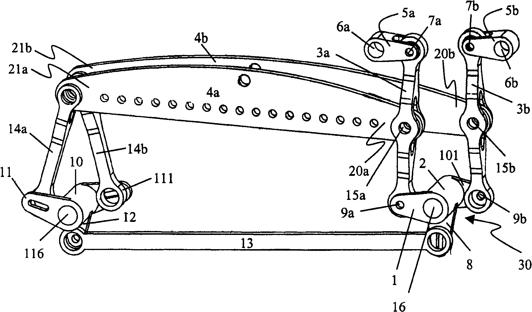
图1示出根据本发明提花织机的第一实施例;Figure 1 shows a first embodiment of a jacquard loom according to the invention;
图2示出根据本发明提花织机的第二实施例;Figure 2 shows a second embodiment of a jacquard loom according to the invention;
图3示出根据本发明提花织机的第三实施例;和Figure 3 shows a third embodiment of a jacquard loom according to the invention; and
图4示出图3中的提花织机实施例的一部分。FIG. 4 shows a part of the embodiment of the Jacquard loom in FIG. 3 .
具体实施方式Detailed ways
根据本发明的提花织机包括两组上下反向运动的刀具,其中每组刀具均在其末端接纳在由电影机式传动链30驱动的分开的刀架4a、4b上,并且每组刀架均借助于“瓦特联接”棒系统引导在其末端20a、20b之一上进行直线运动。这些刀架4a、4b的末端20a、20b每一个的提升高度(行程)都是可调节的。每个刀架4a、4b均在其第一末端20a、20b借助于第一连接棒3a、3b与至少一个第一传动杆2、2a、2b、10联接,并在其第二末端21a,21b借助于第二连接棒14a、14b与至少一个第二传动杆2、10联接。对于每个刀架4a、4b,瓦特联接棒系统均有一个或者几个零件1、101、1a、1b、3a、3b是电影机式传动链30的一部分。而且,在瓦特联接棒系统的第一棒1、101、1a、1b与第三棒3a、3b之间的联接点9a、9b之前(相对于驱动电机),在电影机式传动链30中刀架4a、4b所述末端20a、20b的运动幅度是可调节的。The jacquard loom according to the present invention comprises two sets of knives that move up and down in opposite directions, wherein each set of knives is received at its end on separate knife rests 4a, 4b driven by a cinema-
优选的是,瓦特联接棒系统30中一个最远的棒1、101、1a、1b是电影机式传动链的一部分。Preferably, one of the furthest rods 1, 101, 1a, 1b of the Watts
刀架4a、4b的瓦特联接棒系统可位于刀架4a、4b的相同末端20a、20b;21a、21b(如图1和3所示),也可位于刀架4a、4b的不同末端20a、21b;21a、20b(如图2所示)。The Watt coupling bar system of the
在图1中示出了根据本发明提花织机的第一实施例,其中每一刀架4a、4b的两个末端均设有联接棒3a、3b;14a、14b,用以驱动在提花织机一侧的刀架4a、4b,使其进行上下反向运动。而且,设置两个传动杆2、10用于驱动该联接棒3a、3b;14a、14b,这两个传动杆2、10相互联接在一起,每个传动杆2、10均设有两个杆臂1、101;11、111,设计得使同一传动杆2、10的杆臂1、101;11、111进行反向的运动。这些杆臂1、101;11、111中每一个均与其中一个刀架4a、4b的一个末端20a、21b;21a、20b联接。与不同刀架4a、4b的所述末端20a、20b之一联接的所述联接棒的两个3a、3b具有联接棒3a、3b与杆臂1、101之间的第一联接点9a、9b,和联接棒3a、3b与相应刀架4a、4b的末端20a、20b之间的第二联接点15a、15b,并沿着这两个联接点9a、15a,9b、15b间连线的延长线穿经过第三联接点7a、7b继续延伸,所述第三联接点7a、7b距第二联接点15a、15b的距离与第二联接点15a、15b距第一联接点9a、9b的距离相同,但远离第一联接点9a、9b,它使联接棒3a、3b与瓦特联接棒系统的第二棒5联接,所述第二棒5在它的最远位置设有固定的轴承6a、6b,固定的轴承6a、6b与第三联接点7a、7b之间的距离与第一联接点9a、9b与传动杆2、10绕之摇摆的铰接点16、116之间的距离实质上相等。In Fig. 1, a first embodiment of a jacquard loom according to the present invention is shown, wherein the two ends of each
以此方式,以杆臂1、联接棒3a和第二棒5a为一方面而杆臂11、联接棒3b和第二棒5b为另一方面各自构成具有一个瓦特联接,其特性是联接棒3a、3b与相应刀架4a、4b末端之间的联接点15a、15b进行一种实质上直线的运动。为实现该直线引导,每一直线引导件仅需在电影机式传动链上增设一个棒(杆)5a、5b和两个轴承6a、6b;7a、7b。这两个轴承6a、6b;7a、7b涉及第二棒的所述固定的轴承以及所述第三联接点中的轴承。In this way, with the lever arm 1, the
然而,由于在图1中用于两个刀架4a、4b的瓦特联接棒系统都与一个传动杆2、10的杆臂1、11;101、111联接,并且两个刀架进行反向的运动,所以两个杆臂在直径上实质上彼此对置,这意味着与这两个刀架4a、4b联接的联接点15a、15b彼此之间有一定距离,而且对于这两个刀架4a、4b其中的一个,联接点15a、15b距该侧最后一个刀具的距离比另一个刀架4a、4b联接点距其侧的最后一个刀具的距离要远。其结果是,两个刀架4a、4b尺寸不同且具有不同的刚性。However, since in Fig. 1 the Watt coupling bar system used for the two
在图2和3中示出解决这个问题的解决方案。A solution to this problem is shown in FIGS. 2 and 3 .
在图2中示出了根据本发明提花织机的第二优选实施例,其中每一刀架4a、4b均在其两个末端设有联接棒3a、3b;14a、14b,用以驱动在提花织机一侧的刀架4a、4b,使其进行上下反向运动,设有两个传动杆2、10,用于驱动联接棒3a、3b、14a、14b,并且每个传动杆2、10均设有两个杆臂1、101、11、111,联接棒3a、3b、14a、14b构成刀架4a、4b的末端20a、20b、21a、21b与传动杆2、10的杆臂1、101、11、111之间的联接。每个传动杆2、10均设有第三杆臂8,该第三杆臂8借助于联接棒13a、13b与第三杆17的杆臂18.1、18.2联接,第三杆17被摇摆地驱动,并把该摇摆运动传递给传动杆2、10,传动杆2、10再驱动刀架4a、4b。与不同刀架4a、4b的末端20a、21b之一联接的所述联接棒的两个3a、3b具有联接棒3a、3b与杆臂1、101之间的第一联接点9a、9b和联接棒3a、3b与相应刀架4a、4b的末端20a、21b之间的第二联接点15a、15b,并沿着这两个联接点9a、15a,9b、15b间连线的延长线穿经第三联接点7a、7b继续延伸,所述第三联接点7a、7b距第二联接点15a、15b的距离与第二联接点15a、15b距第一联接点9a、9b的距离相同,但远离第一联接点9a、9b,并且把联接棒3a、3b与瓦特联接棒系统的第二棒5相联接,所述第二棒5在它的最远位置设有固定的轴承6a、6b,并且固定的轴承6a、6b与第三联接点7a、7b之间的距离和第一联接点9a、9b与传动杆2、10绕之摇摆的铰接点16、116之间的距离大致相等。In Fig. 2 there is shown a second preferred embodiment of the jacquard loom according to the present invention, wherein each
优选的是,所述第三杆17由具有连续旋转输入端和摇摆输出端的传动箱驱动,作摇摆运动。而且,还可能(在图中未示出)用一个槽进行非瓦特联接棒系统一个部件的联接棒14a、14b与相应传动杆2、10的臂11、111之间的联接,从而刀架4a、4b的这些末端20b、21b可独立于它们的末端20a、21b进行调节,与这些末端联接的联接棒3a、3b合并在电影机式传动链30的瓦特联接棒系统中。Preferably, the
在图3中示出了根据本发明提花织机的第三优选实施例,其中每一刀架4a、4b均在其第一末端20a、20b处设有第一联接棒3a、3b,并且在其第二末端21a、21b处设有第二联接棒14a、14b,这些联接棒3a、3b、14a、14b设置用于驱动在提花织机一侧的刀架4a、4b,使其进行上下反向运动。每个联接棒3a、3b都把联接刀架4a、4b的第一末端20a、20b与第一杆臂1a、1b中的分开的第一传动杆2a、2b相联接,并且设有第三杆臂8a、8b,与之联接的一个联接棒13a、13b构成其与第二传动杆10的杆臂12a、12b之间的联接,另外该第二传动杆10设有第二联接棒14a、14b与之联接的一个或者几个杆臂11a、11b。所述联接棒中的两个3a、3b与相应刀架4a、4b的末端之一20a、20b相联接,这两个联接棒3a、3b具有联接棒3a、3b与杆臂1a、1b之间的第一联接点9a、9b和联接棒3a、3b与相应刀架4a、4b的末端20a、20b之间的第二联接点15a、15b。联接棒3a、3b沿这两个联接点9a、15a,9b、15b间连线的延长线穿经第三联接点7a、7b继续延伸,所述第三联接点距第二联接点15a、15b与第二联接点15a、15b距第一联接点9a、9b的距离相同,但是远离第一联接点9a、9b,并且所述第三联接点把联接棒3a、3b与瓦特联接棒系统的第二棒5相联接。该第二棒5在它的最远位置设有固定的轴承6a、6b,并且固定的轴承6a、6b与第三联接点7a、7b之间的距离和第一联接点9a、9b与传动杆2、10绕之摇摆的铰接点16、116之间的距离实质上相等。In Fig. 3 is shown a third preferred embodiment of a jacquard loom according to the invention, wherein each
优选的是,第二传动杆10设有两个第一杆臂12a、12b和两个第二杆臂11a、11b。Preferably, the
优选的是,第一传动杆2a、2b绕之摇摆的铰接点16a、16b位于同一轴线27上的一条直线上,从而使得该瓦特联接的铰接点6a、6b位于同一轴线28上的一条直线上。这使得该固定的铰接点6a、6b能安装在固定的公同轴28上,因此相对于图1和图2简化了结构。Preferably, the hinge points 16a, 16b about which the first transmission rods 2a, 2b oscillate lie on a straight line on the same axis 27, so that the
在图1和图2中,两个瓦特联接棒系统在刀架4a、4b的相同或者不同的末端联接两个不同的传动杆2、10;2a、2b,使得两个刀架4a、4b都能够设计成有相同的长度,并且使两组刀具都得到类似的刚性。In Figures 1 and 2, two Watt coupling bar systems couple two
如图1到图3所示的这三个实施例中,刀架4a、4b的末端20a、20b、21a、21b的行程可调节性在杆臂1、11中不再出现,这在现有技术中很常见。根据现有技术,行程调节是通过沿所述传动杆的所述杆臂移动用于驱动刀架运动的第二传动杆杆臂与一个联接棒之间的联接点来进行,所述联接棒是在所述第二传动杆与所述刀架之间。通过提供杆臂的这种可调节的长度,不能保证瓦特联接棒系统的第一和第二棒的杆臂具有相同长度,而要获得第三棒中心的直线运动,这一点却是必需的。In these three embodiments shown in Figures 1 to 3, the stroke adjustability of the
通过在电影机式传动链30中把行程调节到更远位置,即更接近驱动电机,就可真正地使用整体的瓦特联接棒系统。因此,在图1和图3中,优选的是,使刀架4a、4b的所述末端20a、20b的运动幅度在第一和第二传动杆2、2a、2b、10的杆臂8、8a、8b(它不是瓦特联接棒系统的一部分)中可以调节。结果,在图1所示的实施例中经纱的调节总是通过杆臂1、11对与杆2联接的刀架4a、4b的这两个末端同时进行。在根据图3的实施例中,通过在相应杆2a、2b的两个臂8a、8b中都提供提升高度的可调节性,就能够分开地对两个刀架4a、4b的末端调节。在图2中,不同刀架4a、4b的行程的可调节性转移到第三杆1 7上,并且两个刀架的末端都可以分开地进行调节。By adjusting the travel farther in the
在图2和图3中,刀架4a、4b可具有相同尺寸,以使两组刀具具有相同的刚性。在图3中示出了两组刀座19a、19b(每个刀架4a、4b各一个),其中可以吊装一个提花织机的刀具(在该图中没有示出)。In Figures 2 and 3, the
在图4中示出了图3实施例的一部分,其中有可能实现与驱动刀架4a、4b其它末端21a、21b和电影机式传动链30其余部分的不同变例的联接。In FIG. 4 a part of the embodiment of FIG. 3 is shown, in which it is possible to realize a coupling with different variants of the other ends 21a, 21b of the
根据本发明的提花织机与织机结合使用,所述织机既可以是单层织物织机(single weaving machine)也可以是双层绒头织物织机(face-to-face weavingmachine)。The jacquard loom according to the invention is used in combination with a loom which can be either a single weaving machine or a face-to-face weaving machine.
Claims (13)
Applications Claiming Priority (2)
| Application Number | Priority Date | Filing Date | Title |
|---|---|---|---|
| BE2005/0185 | 2005-04-08 | ||
| BE2005/0185A BE1016486A4 (en) | 2005-04-08 | 2005-04-08 | JACQUARD DEVICE. |
Publications (2)
| Publication Number | Publication Date |
|---|---|
| CN1844524A CN1844524A (en) | 2006-10-11 |
| CN1844524B true CN1844524B (en) | 2010-11-03 |
Family
ID=35447671
Family Applications (1)
| Application Number | Title | Priority Date | Filing Date |
|---|---|---|---|
| CN2006100753529A Expired - Fee Related CN1844524B (en) | 2005-04-08 | 2006-04-10 | jacquard loom |
Country Status (6)
| Country | Link |
|---|---|
| US (1) | US7610939B2 (en) |
| EP (1) | EP1710330B1 (en) |
| CN (1) | CN1844524B (en) |
| AT (1) | ATE420230T1 (en) |
| BE (1) | BE1016486A4 (en) |
| DE (1) | DE602006004633D1 (en) |
Families Citing this family (13)
| Publication number | Priority date | Publication date | Assignee | Title |
|---|---|---|---|---|
| BE1016559A4 (en) * | 2005-03-21 | 2007-01-09 | Wiele Michel Van De Nv | JACQUARD DEVICE. |
| FR2945825B1 (en) * | 2009-05-19 | 2011-06-24 | Staubli Lyon | CROWN FORMATION DEVICE AND JACQUARD - TYPE WEAVING MACHINE EQUIPPED WITH SUCH A DEVICE. |
| CN102220668B (en) * | 2011-05-31 | 2013-03-13 | 浙江奇汇电子提花机有限公司 | Transmission mechanism for griffs in electronic jacquard |
| CN102505244A (en) * | 2011-10-28 | 2012-06-20 | 吴江市金迪喷织厂 | Cutter bar connector for loom |
| BE1021506B1 (en) * | 2012-11-19 | 2015-12-03 | Nv Michel Van De Wiele | MODULE SUITABLE FOR BUILD-IN IN A JAQUARD MACHINE |
| US8939829B2 (en) * | 2012-12-14 | 2015-01-27 | Cnh Industrial America Llc | Combine linear side-shake cleaning control system |
| US8951105B2 (en) * | 2012-12-21 | 2015-02-10 | Cnh Industrial America Llc | Combine side-shake control system slider joint |
| US10104839B2 (en) * | 2015-07-23 | 2018-10-23 | Cnh Industrial America Llc | Linkage for agricultural harvester cleaner |
| US10080329B2 (en) * | 2015-07-23 | 2018-09-25 | Cnh Industrial America Llc | Side shaker link for agricultural harvester sieve assembly |
| CN105316834A (en) * | 2015-12-04 | 2016-02-10 | 浙江奇汇电子提花机有限公司 | Transmission mechanism of electronic jacquard machine |
| BE1024029B1 (en) * | 2016-04-08 | 2017-11-06 | Nv Michel Van De Wiele | GAAP FORMAT FOR A WEAVING DEVICE |
| CN113136647B (en) * | 2020-01-17 | 2025-01-07 | 广东康派环创科技有限公司 | Jacquard machine type changing device and jacquard machine type changing method |
| CN114592261B (en) * | 2022-03-15 | 2023-10-27 | 嵊州市和丰电子科技有限公司 | Jacquard with low machine body, low weight and high stability |
Citations (2)
| Publication number | Priority date | Publication date | Assignee | Title |
|---|---|---|---|---|
| EP0522216A1 (en) * | 1991-06-28 | 1993-01-13 | Bonas Machine Company Limited | Jacquard mechanism |
| EP0742299A2 (en) * | 1995-05-08 | 1996-11-13 | Kayaba Kogyo Kabushiki Kaisha | Thread selecting device |
Family Cites Families (8)
| Publication number | Priority date | Publication date | Assignee | Title |
|---|---|---|---|---|
| US2083291A (en) * | 1935-01-30 | 1937-06-08 | Camps Juan Picanol | Mechanism for the working and regulation of the healds course |
| GB577980A (en) * | 1943-03-24 | 1946-06-11 | Kapella Ltd | Improvements in or relating to apparatus for measuring or indicating the roughnessesor undulations of a surface |
| US3204476A (en) * | 1960-04-05 | 1965-09-07 | William S Rouverol | Variable speed transmission |
| US3323284A (en) * | 1962-11-05 | 1967-06-06 | Tape Engineering Ltd | Apparatus for handling a web of material |
| US3210994A (en) * | 1963-10-31 | 1965-10-12 | Erwin J Saxl | Tension gage and control for filamentary materials |
| US4047272A (en) * | 1975-12-29 | 1977-09-13 | Hanes Corporation | Machine for continuous bias cutting of tubular fabric |
| CA2067355A1 (en) * | 1989-10-04 | 1991-04-05 | Helmuth R. Uebel | Rotary piston machine |
| US5458359A (en) * | 1994-08-08 | 1995-10-17 | Brandt; Larry A. | Missing link swivel for four-link rigid axle suspensions |
-
2005
- 2005-04-08 BE BE2005/0185A patent/BE1016486A4/en not_active IP Right Cessation
-
2006
- 2006-03-31 DE DE602006004633T patent/DE602006004633D1/en not_active Expired - Lifetime
- 2006-03-31 EP EP06112105A patent/EP1710330B1/en not_active Expired - Lifetime
- 2006-03-31 AT AT06112105T patent/ATE420230T1/en not_active IP Right Cessation
- 2006-04-10 CN CN2006100753529A patent/CN1844524B/en not_active Expired - Fee Related
- 2006-04-10 US US11/401,102 patent/US7610939B2/en active Active
Patent Citations (2)
| Publication number | Priority date | Publication date | Assignee | Title |
|---|---|---|---|---|
| EP0522216A1 (en) * | 1991-06-28 | 1993-01-13 | Bonas Machine Company Limited | Jacquard mechanism |
| EP0742299A2 (en) * | 1995-05-08 | 1996-11-13 | Kayaba Kogyo Kabushiki Kaisha | Thread selecting device |
Also Published As
| Publication number | Publication date |
|---|---|
| BE1016486A4 (en) | 2006-12-05 |
| US7610939B2 (en) | 2009-11-03 |
| US20060249219A1 (en) | 2006-11-09 |
| EP1710330B1 (en) | 2009-01-07 |
| DE602006004633D1 (en) | 2009-02-26 |
| CN1844524A (en) | 2006-10-11 |
| ATE420230T1 (en) | 2009-01-15 |
| EP1710330A1 (en) | 2006-10-11 |
Similar Documents
| Publication | Publication Date | Title |
|---|---|---|
| CN1844524B (en) | jacquard loom | |
| JP2010530034A (en) | Equipment for needling fleece web | |
| KR20090132505A (en) | Kiln drive and multi-duty sewing machine | |
| JP2003183973A (en) | Needle punch device for fiber web | |
| JP2003003360A (en) | Needle punching machine for fiber web | |
| CN1861863B (en) | Jacquard machine | |
| JP2007107128A (en) | Selvedge shedding device in loom | |
| US6463962B2 (en) | Device for guiding the knife-supporting beams in a jacquard machine | |
| JP4057305B2 (en) | Reno fabric manufacturing equipment | |
| CN105593425B (en) | Shuttle embroidery machine | |
| JPH04263643A (en) | Device for controlling reciprocal movement of frame of opening forming device | |
| EP1043148B1 (en) | Press machine | |
| JP4625251B2 (en) | Motion transmission mechanism | |
| CN1774531B (en) | Transmission device of loom heald frame | |
| CN113550077A (en) | Oval Needling Device with Sealed Housing and Tilted Cross Needle Guide Box | |
| RU2202016C1 (en) | Stitch length adjusting device | |
| US4271872A (en) | Drive mechanism for a sub-mechanism of a weaving machine | |
| BE1015419A6 (en) | Selvedge forming device for fabric, comprises thread guiding element provided by drive mechanism such that its position can be laterally changed on one hand, and can be changed in height on the other hand. | |
| RU1807118C (en) | Loom rapier drive | |
| CN101649530A (en) | Transmission mechanism for needle bar of straight-type flat seaming machine | |
| US1115650A (en) | Knitting-machine. | |
| CN201517164U (en) | Straight needle lever transmission mechanism for flat seaming machine | |
| JP3024087B2 (en) | Needle bar lever transmission in sewing machine | |
| CN119711016A (en) | Cam drive jacquard machine with guide system | |
| US583414A (en) | Feeding mechanism for sewing-machines |
Legal Events
| Date | Code | Title | Description |
|---|---|---|---|
| C06 | Publication | ||
| PB01 | Publication | ||
| C10 | Entry into substantive examination | ||
| SE01 | Entry into force of request for substantive examination | ||
| C14 | Grant of patent or utility model | ||
| GR01 | Patent grant | ||
| CF01 | Termination of patent right due to non-payment of annual fee |
Granted publication date: 20101103 |