CN1906339A - Drafting unit with upper delivery roller pair surrounded by a belt - Google Patents
Drafting unit with upper delivery roller pair surrounded by a belt Download PDFInfo
- Publication number
- CN1906339A CN1906339A CNA2004800303884A CN200480030388A CN1906339A CN 1906339 A CN1906339 A CN 1906339A CN A2004800303884 A CNA2004800303884 A CN A2004800303884A CN 200480030388 A CN200480030388 A CN 200480030388A CN 1906339 A CN1906339 A CN 1906339A
- Authority
- CN
- China
- Prior art keywords
- belt
- roller
- drafting system
- deflecting element
- top roller
- Prior art date
- Legal status (The legal status is an assumption and is not a legal conclusion. Google has not performed a legal analysis and makes no representation as to the accuracy of the status listed.)
- Pending
Links
Images

Classifications
-
- D—TEXTILES; PAPER
- D01—NATURAL OR MAN-MADE THREADS OR FIBRES; SPINNING
- D01H—SPINNING OR TWISTING
- D01H5/00—Drafting machines or arrangements ; Threading of roving into drafting machine
- D01H5/18—Drafting machines or arrangements without fallers or like pinned bars
- D01H5/70—Constructional features of drafting elements
- D01H5/86—Aprons; Apron supports; Apron tensioning arrangements
-
- D—TEXTILES; PAPER
- D01—NATURAL OR MAN-MADE THREADS OR FIBRES; SPINNING
- D01H—SPINNING OR TWISTING
- D01H5/00—Drafting machines or arrangements ; Threading of roving into drafting machine
- D01H5/18—Drafting machines or arrangements without fallers or like pinned bars
- D01H5/26—Drafting machines or arrangements without fallers or like pinned bars in which fibres are controlled by one or more endless aprons
Landscapes
- Engineering & Computer Science (AREA)
- Mechanical Engineering (AREA)
- Textile Engineering (AREA)
- Spinning Or Twisting Of Yarns (AREA)
- Preliminary Treatment Of Fibers (AREA)
- Treatment Of Fiber Materials (AREA)
- Rolls And Other Rotary Bodies (AREA)
Abstract
Description
技术领域technical field
本发明涉及一种带有一对上输出罗拉的牵伸装置,在该装置中,皮带被围绕在偏转元件上,该偏转元件安装在背离前罗拉对的压紧表面的区域上。The invention relates to a drafting device with a pair of upper delivery rollers, in which device a belt is wound around a deflection element mounted on the area facing away from the pressing surface of the front roller pair.
背景技术Background technique
当在牵伸装置上牵伸纤维条时,罗拉对的压紧作用对于将牵伸力转移到纤维束上起着决定性的作用。因此,一个牵伸装置的罗拉对由一个低的带沟槽的钢罗拉,即所谓的下罗拉,和一个上面的罗拉,即所谓的上罗拉组成,该上罗拉是通过一个装载设备压在下罗拉上。一般地,这个上罗拉具有一个弹性外层,以便通过弹性外层的变形产生一个压紧表面而不是压线,这个表面致使纤维具有明显更好的保持力。好的压紧作用是在不损坏纤维的前提下施加在纤维束上。经验表明因为外层越是柔软,压紧表面也大,所以柔软的罗拉外层产生更好的牵伸结果。但是,柔软的罗拉外层有这样的缺点,即它们磨损很快,必须重新磨。这会改变牵伸滚筒的几何形状,伴随其也改变外层的特性,而这些改变又会对牵伸条件及纱线质量产生不良的影响。而且,磨罗拉是昂贵的措施。When drafting the sliver on the drafting unit, the compaction of the roller pairs plays a decisive role in transferring the drafting force to the fiber bundle. The roller pair of a drafting unit therefore consists of a low grooved steel roller, the so-called bottom roller, and an upper roller, the so-called top roller, which is pressed against the bottom roller by a loading device. superior. Generally, this top roller has an elastic outer layer, so that the deformation of the elastic outer layer produces a pressing surface instead of a pressing line, which leads to a significantly better retention of the fibers. Good compaction is applied to the fiber bundle without damaging the fibers. Experience has shown that a softer roller outer layer produces better drafting results because the softer the outer layer, the larger the pressing surface. However, soft roller outer layers have the disadvantage that they wear out quickly and must be reground. This changes the geometry of the drafting drum, which in turn changes the properties of the outer layer, and these changes can adversely affect the drafting conditions and thus the yarn quality. Also, grinding rollers is an expensive measure.
为了将罗拉外层的高柔软度与高耐磨性结合起来,从而产生长时间使用下的最优牵伸条件,德国专利DE 102 60 025.2(其不是一个在先公布),建议用高耐磨性的皮带围绕一个带有柔软外层的上罗拉。这个分开的皮带具有这样的优点,即它在磨损或损坏的情况下可容易更换,用不同硬度、不同方法或者一些其他不同类型或者质量的皮带替换。In order to combine the high softness of the outer layer of the roller with high wear resistance, thereby producing the optimal drafting conditions under long-term use, German patent DE 102 60 025.2 (which is not a prior publication) proposes to use high wear resistance The flexible belt surrounds a top roller with a soft outer layer. This separate belt has the advantage that it can be easily replaced in case of wear or damage, by a belt of a different hardness, a different method or some other different type or quality.
这个解决方案是有利的,特别是用在牵伸装置的前罗拉对,在该牵伸装置中,罗拉运转特别快且最大程度影响着可靠的牵伸,这是显而易见的。This solution is advantageous especially for the front roller pair of a drafting arrangement, where the rollers run particularly fast and have the greatest influence on reliable drafting, as is evident.
用皮带围绕牵伸装置的前上罗拉是公开的(DE 816 069;DE-GM R7,1949年10月1日),这些相当长的皮带的目的在于防止在前罗拉对的上罗拉周围形成缠绕。这些皮带与拉紧装置结合在一起,拉紧装置使它们处于牵引张力下,从而使它们保持绷紧。Belts around the front top rollers of the drafting unit are known (DE 816 069; DE-GM R7, 1 October 1949), the purpose of these rather long belts is to prevent the formation of tangles around the top rollers of the front roller pair . These straps are combined with a tensioning device that puts them under traction tension so that they stay taut.
发明内容Contents of the invention
皮带经由固定的偏转元件被引导到这些拉紧装置上。事实表明,将皮带拉到这些偏转元件上时要消耗驱动能量,皮带经历一个刹车过程,刹车对牵伸过程产生不良的影响,且使皮带遭受磨损。因此,本发明所要解决的技术问题在于避免这些缺点。本发明公开一种将皮带围绕在牵伸装置的前上罗拉对的方法,其中皮带围绕在偏转元件上,该偏转元件安装在背离前罗拉对的压紧表面的区域上,所述的皮带基本上只受到微小的牵引张力,该张力是由于皮带趋向于在圆周方向上呈现圆形而引起的。本发明还公开一种带有被皮带围绕的前上罗拉对的牵伸装置,在该装置中,皮带围绕在偏转元件上,该偏转元件安装在背离前面的罗拉对的压紧表面的区域上,上罗拉对的两个偏转元件在一个整体式的坚硬的支座上形成,该支座以可拆卸的方式固定在与该上罗拉对连接在一起的一个构件上。The belt is guided onto these tensioning devices via fixed deflection elements. It has been shown that driving energy is consumed in pulling the belt over these deflection elements, that the belt undergoes a braking process which adversely affects the drawing process and that the belt is subject to wear. Therefore, the technical problem to be solved by the present invention is to avoid these disadvantages. The invention discloses a method for wrapping a belt around a pair of front top rollers of a drafting device, wherein the belt is wrapped around a deflection element mounted on an area facing away from the pressing surface of the front roller pair, said belt essentially The belt is only subjected to slight traction tension caused by the tendency of the belt to assume a circular shape in the circumferential direction. The invention also discloses a drafting device with a front top roller pair surrounded by a belt, in which device the belt wraps around a deflection element mounted on the area facing away from the pressing surface of the front roller pair , the two deflection elements of the top roller pair are formed on an integral rigid support, which is fixed in a detachable manner on a member connected to the top roller pair.
为了使在皮带上的牵引张力尽可能低,因此使用在无载荷的状态下,趋向于在圆周方向上呈现近似圆形的皮带。由于皮带一般由合成材料组成,因此提供了这个趋势。在前上罗拉和偏转元件的支撑面之间的间隔是这样选取,由于在圆周方向上趋向呈现圆形的趋势,使得皮带在上罗拉和偏转元件之间的区域内向外拱起。然后它们只以微小的压力支撑在偏转元件上,因而它们只处在一个很小的牵引张力下。因此,它们实际上不经历刹车,不消耗驱动能量并且不遭受磨损。In order to keep the traction tension on the belt as low as possible, a belt which tends to be approximately circular in the circumferential direction in the unloaded state is used. This trend is provided since belts are generally composed of synthetic materials. The distance between the front top roller and the support surface of the deflection element is chosen such that the belt arches outwards in the region between the top roller and the deflection element due to the tendency to round in the circumferential direction. They are then supported on the deflection element with only slight pressure, so that they are only under a low traction tension. Therefore, they experience virtually no braking, consume no driving energy and are not subject to wear.
如果在皮带的内转动层和偏转元件之间的摩擦系数通过材料的适当匹配保持尽可能低,效果将更加有利。It is even more advantageous if the coefficient of friction between the inner rotating layer of the belt and the deflection element is kept as low as possible by a suitable adaptation of the materials.
如果争取圆形的直径为被围绕的上罗拉的周长的约1到3倍,并且被围绕的上罗拉和偏转元件之间的间隔为被围绕的上罗拉直径的一半到两倍,那么可获得皮带在偏转元件上的低的接触压力。If the diameter of the circle is about 1 to 3 times the circumference of the surrounded top roller, and the spacing between the surrounded top roller and the deflection element is half to twice the diameter of the surrounded top roller, then A low contact pressure of the belt on the deflection element can be achieved.
在本实例中,一对上罗拉的两个偏转元件可在一个整体式的坚硬的支座上形成,优选地,该支座以可拆卸的方式固定在与该对上罗拉连接在一起的一个构件上。该支座可以包含一个握持元件,该握持元件可以连接到该对上罗拉的轴上,或者它可以固定在该对上罗拉的导杆上或者上罗拉的支撑或者负载臂上。In this example, the two deflection elements of a pair of top rollers can be formed on an integral rigid support, preferably detachably fixed to a pair of top rollers connected together. on the component. The support may comprise a gripping element, which may be connected to the shaft of the pair of top rollers, or it may be fixed on the guide rods of the pair of top rollers or on the support or load arms of the top rollers.
为皮带的侧向制导设有支撑面。A supporting surface is provided for the lateral guidance of the belt.
附图说明Description of drawings
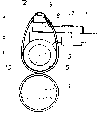
附图显示了本发明的两个优选实施例。The accompanying drawings show two preferred embodiments of the invention.
图1是本发明的第一个实施例中的牵伸装置的正视图,以在平面A-A内的截面图表示;Figure 1 is a front view of a drafting device in a first embodiment of the present invention, represented as a sectional view in plane A-A;
图2是图1主题的侧视图;Figure 2 is a side view of the subject of Figure 1;
图3另一种固定支座方法的正视图;The front view of another kind of fixed bearing method of Fig. 3;
图4是图3主题的侧视图。FIG. 4 is a side view of the subject matter of FIG. 3 .
附图标记说明:Explanation of reference signs:
1:前下罗拉1: front bottom roller
2:上罗拉对2: Upper roller pair
3:上罗拉3: top roller
4:上罗拉4: top roller
5:上罗拉3,4的涂层5: Coating of
6:上罗拉对的轴6: The shaft of the top roller pair
7:导杆7: guide rod
8:支座8: Support
9:支座8上的偏转元件9: Deflection element on
10:皮带10: belt
11:皮带11: belt
12:支座8上的握持元件12: Holding element on
13:偏转元件9的支撑面13: Support surface for
14:支座8上的套环14: Collar on
15:支座8上的套环15: Collar on
16:支座8的中间区域16: Middle area of
17:夹子17: clip
具体实施方式Detailed ways
本发明以普通设计的牵伸装置开始,该牵伸装置包含一个前面的下钢罗拉1,在机器的整个长度上运转,在该下罗拉上支撑着上罗拉对2,在图1的正视图中只显示了其中一个上罗拉。上罗拉对的两个上罗拉3、4包含一个优选为柔软的外层5,以获得上述的有利的牵伸条件。通过轴6的夹持,它们被连接到弹簧导杆7上。导杆7安装在上罗拉的支撑或者负载臂上(未示出)。The invention starts with a drafting unit of common design comprising a front lower steel roller 1, running over the entire length of the machine, on which upper roller pair 2 is supported, front view in Fig. 1 Only one of the top rollers is shown. The two
根据本发明,提供整体式的支座8,其优选由铸件制造,两个偏转元件9从支座侧面伸出,皮带10,11也围绕在上罗拉3,4上运转。偏转元件9具有深入的支承面12,其由套环14,15限制住,这样当牵伸装置运转时,皮带不会侧向地从上罗拉3,4上滑落。According to the invention, a one-
图2中,从皮带10、11在上罗拉3、4和偏转元件9之间的拱起可认识到,它们只是宽松地被围绕在偏转元件上,因此只是处于微小的压力下,该压力仅仅是由于皮带趋向于在圆周方向上呈现圆形而引起的。In Fig. 2, it can be recognized from the arching of the
对于皮带的作用模式,如果它们具有上罗拉3、4的周长的约1的周长,这就足够了。在上罗拉的旋转轴和偏转元件9的支撑面12之间的间隔a约为上罗拉的直径。但是,皮带的周长也可以增加到上罗拉的周长的大约三倍,或者在某些情况甚至更大,即如图3所示,在上罗拉的旋转轴和偏转元件9的支撑面12之间的间隔a应被增加到至少为上罗拉直径的约两倍。可理解为,间隔a必须同周长具有适当比例关系,也必须同皮带10、11的硬度具有适当比例。在皮带特别坚硬的情况下,间隔a应当减小。For the mode of action of the belts, it is sufficient if they have a circumference of about 1 of the circumference of the
图1、2中的实施例的支座8包含两个握持元件15,这些握持元件可以被夹持在连接的上罗拉对的轴6上,并且其对支座起导向作用。这样,如果需要更换上罗拉3、4或者皮带10、11,装置可以容易地从导杆7上拆卸。为此,轴6被向下夹持在导杆之外,握持元件15是向着离开轴的方向被枢轴连接到前部的。当牵伸装置运转时,在图2的侧视图中,支座8趋向于随着上罗拉3、4像时钟一样地旋转。为了阻止这样的旋转,设计这样的设备:其可以最简单的外形由导杆7的上侧面形成,支座8的中间区域16支撑在这些上侧面上。The
在图3、4的实施例中,支座8可以通过与支座连接的弹性夹扣板17夹持在导杆7上。在这个例子中,支座8已经这样固定使得它们和谐旋转。In the embodiment shown in FIGS. 3 and 4 , the
支座8也可以接合在上罗拉的支撑或者负载臂上,这一点在图中没有详细表达。在这个例子中,它们例如可以被设置到上清洁罗拉的支座内,当使用围绕的皮带时,一般不再需要这些清洁罗拉。The
优选地,皮带10、11由至少两层组成,其中与纤维接触的外层满足好的纤维压紧和低磨损的要求,偏转元件9的支撑面12满足低摩擦运转的要求。Preferably, the
Claims (11)
Applications Claiming Priority (2)
| Application Number | Priority Date | Filing Date | Title |
|---|---|---|---|
| DE10348452.3 | 2003-10-17 | ||
| DE10348452A DE10348452B4 (en) | 2003-10-17 | 2003-10-17 | Drafting system with twin top rollers wrapped in aprons |
Related Child Applications (1)
| Application Number | Title | Priority Date | Filing Date |
|---|---|---|---|
| CN201210394215.7A Division CN103088483B (en) | 2003-10-17 | 2004-10-14 | Drawing frame with aprons entwined around twin output top delivery rollers |
Publications (1)
| Publication Number | Publication Date |
|---|---|
| CN1906339A true CN1906339A (en) | 2007-01-31 |
Family
ID=34442075
Family Applications (2)
| Application Number | Title | Priority Date | Filing Date |
|---|---|---|---|
| CN201210394215.7A Expired - Fee Related CN103088483B (en) | 2003-10-17 | 2004-10-14 | Drawing frame with aprons entwined around twin output top delivery rollers |
| CNA2004800303884A Pending CN1906339A (en) | 2003-10-17 | 2004-10-14 | Drafting unit with upper delivery roller pair surrounded by a belt |
Family Applications Before (1)
| Application Number | Title | Priority Date | Filing Date |
|---|---|---|---|
| CN201210394215.7A Expired - Fee Related CN103088483B (en) | 2003-10-17 | 2004-10-14 | Drawing frame with aprons entwined around twin output top delivery rollers |
Country Status (8)
| Country | Link |
|---|---|
| US (1) | US7475531B2 (en) |
| EP (1) | EP1673497B1 (en) |
| JP (1) | JP4639193B2 (en) |
| CN (2) | CN103088483B (en) |
| AT (1) | ATE407240T1 (en) |
| DE (2) | DE10348452B4 (en) |
| ES (1) | ES2313088T3 (en) |
| WO (1) | WO2005038104A1 (en) |
Families Citing this family (8)
| Publication number | Priority date | Publication date | Assignee | Title |
|---|---|---|---|---|
| DE102006011128B4 (en) * | 2006-03-08 | 2016-04-28 | Deutsche Institute für Textil- und Faserforschung Stuttgart | Roll stretching device |
| DE102008010364A1 (en) | 2008-02-18 | 2009-08-20 | Spindelfabrik Suessen Gmbh | Riemchenführungseinrichtung for a drafting top roller |
| WO2010016808A1 (en) * | 2008-08-04 | 2010-02-11 | Ozdilek Alisveris Merkezleri Ve Tekstil Sanayi Anonim Sirketi | Compact yarn manufacturing system |
| EP2414570B1 (en) * | 2009-03-31 | 2016-05-11 | Ozdilek Ev Tekstil Sanayi Ve Ticaret Anonim Sirketi | System comprising fibers and a fibre drafting mechanism, and related method |
| CN101876110B (en) * | 2010-07-30 | 2011-12-28 | 宁波民丰实业有限公司 | Full carbon fiber top pin with plug-in tail structure and manufacturing method thereof |
| CH710141A1 (en) * | 2014-09-23 | 2016-03-31 | Rieter Ag Maschf | Cage assembly with a guide element for a drafting arrangement of a textile machine. |
| DE102016210514B3 (en) * | 2016-06-14 | 2017-08-24 | Siemens Aktiengesellschaft | Multi-part apron for a vehicle |
| CN114293291B (en) * | 2021-12-31 | 2022-12-09 | 安徽兰翔智能制造有限公司 | Weaving rubber ring subassembly convenient to change |
Family Cites Families (25)
| Publication number | Priority date | Publication date | Assignee | Title |
|---|---|---|---|---|
| NL42235C (en) * | 1900-01-01 | |||
| US2231526A (en) * | 1941-02-11 | Mechanism for | ||
| US2193196A (en) * | 1937-06-15 | 1940-03-12 | H & B American Machine Company | Mechanism for drawing textile slivers or rovings |
| DE816069C (en) * | 1950-03-08 | 1951-10-08 | Deutscher Spinnereimaschb Ingo | Drafting system for spinning machines |
| CH360327A (en) * | 1956-08-31 | 1962-02-15 | Oskar Dipl Phys Koenig | Drafting system for drawing fiber structures |
| GB841583A (en) * | 1957-03-25 | 1960-07-20 | Spintex Spinnerei Maschb G M B | Improvements in or relating to an apron tensioning device for a fibre drawing arrangement |
| US2943361A (en) * | 1957-04-15 | 1960-07-05 | Machinecraft Inc | Spinning frame apron guides |
| US2856643A (en) * | 1958-02-10 | 1958-10-21 | Whitin Machine Works | Apparatus for drafting relatively long textile fibers |
| GB1184793A (en) * | 1960-11-20 | 1970-03-18 | Mackie & Sons Ltd J | Improvements relating to Textile Drafting Apparatus |
| GB1184787A (en) * | 1960-11-20 | 1970-03-18 | Mackie & Sons Ltd J | Improvements relating to Textile Drafting Apparatus |
| GB1250622A (en) * | 1968-05-13 | 1971-10-20 | ||
| FR1593755A (en) * | 1968-11-28 | 1970-06-01 | ||
| SU494454A1 (en) * | 1973-05-24 | 1975-12-05 | Костромское Специальное Конструкторское Бюро Текстильных Машин | The strap of the upper strap double strap exhaust device |
| CH603840A5 (en) * | 1975-09-12 | 1978-08-31 | Rieter Ag Maschf | |
| JPS5430937A (en) * | 1977-08-05 | 1979-03-07 | Shiyouhou Miwa | Apron draft system of spinning machine |
| SU701181A1 (en) * | 1977-11-21 | 1981-09-07 | Ташкентское Специальное Конструкторское Бюро Текстильных Машин | Upper lattice of double-belt stretching device of textile machine |
| GB2058850B (en) * | 1979-09-25 | 1984-02-15 | Tashkentslspetsial Konstrukt B | Pressure roll for a drafting device for a textile machine |
| EP0099973B1 (en) * | 1982-07-23 | 1985-09-11 | Maschinenfabrik Rieter Ag | Drawing frame for a spinning machine |
| US4513481A (en) * | 1982-09-02 | 1985-04-30 | Kabushiki Kaisha Toyoda Jidoshokki Seisakusho | Easily displaceable bottom tenser |
| JPH0194473U (en) * | 1987-12-10 | 1989-06-21 | ||
| DE3908651A1 (en) * | 1989-03-16 | 1990-09-20 | Skf Textilmasch Komponenten | Drawframe for spinning machines with a double-apron assembly |
| JP3438584B2 (en) * | 1998-05-08 | 2003-08-18 | 株式会社豊田自動織機 | Top apron cradle in spinning machine |
| DE19837181A1 (en) * | 1998-08-17 | 2000-02-24 | Stahlecker Fritz | Apparatus to condense drawn sliver has a belt to carry the sliver over a sliding surface with a suction slit to be pressed against the surface by a clamping roller |
| DE19907905C2 (en) * | 1999-02-24 | 2002-06-20 | Skf Textilmasch Komponenten | Roller for apron drafting systems |
| DE10260025A1 (en) * | 2002-12-19 | 2004-07-08 | Deutsche Institute für Textil- und Faserforschung (DITF) | Coating for drafting rollers |
-
2003
- 2003-10-17 DE DE10348452A patent/DE10348452B4/en not_active Expired - Fee Related
-
2004
- 2004-10-14 JP JP2006534679A patent/JP4639193B2/en not_active Expired - Fee Related
- 2004-10-14 EP EP04790385A patent/EP1673497B1/en not_active Expired - Lifetime
- 2004-10-14 CN CN201210394215.7A patent/CN103088483B/en not_active Expired - Fee Related
- 2004-10-14 WO PCT/EP2004/011522 patent/WO2005038104A1/en not_active Ceased
- 2004-10-14 AT AT04790385T patent/ATE407240T1/en not_active IP Right Cessation
- 2004-10-14 DE DE502004007999T patent/DE502004007999D1/en not_active Expired - Lifetime
- 2004-10-14 CN CNA2004800303884A patent/CN1906339A/en active Pending
- 2004-10-14 ES ES04790385T patent/ES2313088T3/en not_active Expired - Lifetime
- 2004-10-14 US US10/575,372 patent/US7475531B2/en not_active Expired - Fee Related
Also Published As
| Publication number | Publication date |
|---|---|
| DE10348452A1 (en) | 2005-05-25 |
| ES2313088T3 (en) | 2009-03-01 |
| US7475531B2 (en) | 2009-01-13 |
| CN103088483B (en) | 2015-06-24 |
| DE10348452B4 (en) | 2008-07-03 |
| CN103088483A (en) | 2013-05-08 |
| ATE407240T1 (en) | 2008-09-15 |
| DE502004007999D1 (en) | 2008-10-16 |
| US20070169459A1 (en) | 2007-07-26 |
| EP1673497A1 (en) | 2006-06-28 |
| JP2007508472A (en) | 2007-04-05 |
| EP1673497B1 (en) | 2008-09-03 |
| WO2005038104A1 (en) | 2005-04-28 |
| JP4639193B2 (en) | 2011-02-23 |
Similar Documents
| Publication | Publication Date | Title |
|---|---|---|
| JP5711062B2 (en) | Spinning winder | |
| JP2008044790A5 (en) | ||
| CN1017636B (en) | Enclosed shoe press | |
| CN103088483B (en) | Drawing frame with aprons entwined around twin output top delivery rollers | |
| CN1309201A (en) | Friction feed burr mechanism with vibration excitation | |
| JP6228192B2 (en) | Winding device | |
| JP4454501B2 (en) | Draft roller cover | |
| CN102449212B (en) | Yarn drafting mechanism and method | |
| CN1319830C (en) | Conveyer for producing winding roll | |
| CN1448557A (en) | Drawing frame for a spinning machine | |
| CH622831A5 (en) | ||
| EP2561982A1 (en) | An installation for compacting paper and method of using the same | |
| CN101395309A (en) | Wear-resistant coating for the delivery roll of a roll drafting system | |
| FR2825693A1 (en) | TURNING TRAY FOR FIBER TAPE DEPOSIT EXIT FROM DRAWING BENCHES OR CARDS | |
| FR2825694A1 (en) | TUNING TRAY OF FIBER TAPE DEPOSITION DEVICES IN CARDS, DRAWING BENCHES | |
| CN202012022U (en) | Treatment device with annular metal tape | |
| US1494991A (en) | Mechanism for the drawing of textile rovings | |
| JP3732889B2 (en) | Conveying toothed belt and conveying toothed belt drive device | |
| CN111210953A (en) | Strand frame of a cantilever single stranding machine | |
| CN1924130A (en) | Ring fine spinning machine machinery centralization type compact spinning apparatus | |
| CN214494480U (en) | High-performance conveying belt | |
| CN212742004U (en) | Paper machine wire section forming device | |
| EP0735171A1 (en) | Apparatus for feeding and tensioning threads in a textile machine | |
| EP1550626B1 (en) | Apparatus for transporting sheets along a transport track with a bend passing around a transport roller | |
| GB2080345A (en) | Yarn false twisting apparatus |
Legal Events
| Date | Code | Title | Description |
|---|---|---|---|
| C06 | Publication | ||
| PB01 | Publication | ||
| C10 | Entry into substantive examination | ||
| SE01 | Entry into force of request for substantive examination | ||
| C12 | Rejection of a patent application after its publication | ||
| RJ01 | Rejection of invention patent application after publication |
Application publication date: 20070131 |