CN1908383B - Gas turbine on-line compressor water wash system - Google Patents
Gas turbine on-line compressor water wash system Download PDFInfo
- Publication number
- CN1908383B CN1908383B CN2006101091840A CN200610109184A CN1908383B CN 1908383 B CN1908383 B CN 1908383B CN 2006101091840 A CN2006101091840 A CN 2006101091840A CN 200610109184 A CN200610109184 A CN 200610109184A CN 1908383 B CN1908383 B CN 1908383B
- Authority
- CN
- China
- Prior art keywords
- water
- nozzles
- washing system
- water washing
- rotating blades
- Prior art date
- Legal status (The legal status is an assumption and is not a legal conclusion. Google has not performed a legal analysis and makes no representation as to the accuracy of the status listed.)
- Expired - Fee Related
Links
Images


Classifications
-
- F—MECHANICAL ENGINEERING; LIGHTING; HEATING; WEAPONS; BLASTING
- F04—POSITIVE - DISPLACEMENT MACHINES FOR LIQUIDS; PUMPS FOR LIQUIDS OR ELASTIC FLUIDS
- F04D—NON-POSITIVE-DISPLACEMENT PUMPS
- F04D29/00—Details, component parts, or accessories
- F04D29/70—Suction grids; Strainers; Dust separation; Cleaning
- F04D29/701—Suction grids; Strainers; Dust separation; Cleaning especially adapted for elastic fluid pumps
- F04D29/705—Adding liquids
-
- F—MECHANICAL ENGINEERING; LIGHTING; HEATING; WEAPONS; BLASTING
- F01—MACHINES OR ENGINES IN GENERAL; ENGINE PLANTS IN GENERAL; STEAM ENGINES
- F01D—NON-POSITIVE DISPLACEMENT MACHINES OR ENGINES, e.g. STEAM TURBINES
- F01D25/00—Component parts, details, or accessories, not provided for in, or of interest apart from, other groups
- F01D25/002—Cleaning of turbomachines
-
- F—MECHANICAL ENGINEERING; LIGHTING; HEATING; WEAPONS; BLASTING
- F02—COMBUSTION ENGINES; HOT-GAS OR COMBUSTION-PRODUCT ENGINE PLANTS
- F02C—GAS-TURBINE PLANTS; AIR INTAKES FOR JET-PROPULSION PLANTS; CONTROLLING FUEL SUPPLY IN AIR-BREATHING JET-PROPULSION PLANTS
- F02C7/00—Features, components parts, details or accessories, not provided for in, or of interest apart form groups F02C1/00 - F02C6/00; Air intakes for jet-propulsion plants
- F02C7/12—Cooling of plants
- F02C7/14—Cooling of plants of fluids in the plant, e.g. lubricant or fuel
- F02C7/141—Cooling of plants of fluids in the plant, e.g. lubricant or fuel of working fluid
- F02C7/143—Cooling of plants of fluids in the plant, e.g. lubricant or fuel of working fluid before or between the compressor stages
- F02C7/1435—Cooling of plants of fluids in the plant, e.g. lubricant or fuel of working fluid before or between the compressor stages by water injection
Landscapes
- Engineering & Computer Science (AREA)
- Mechanical Engineering (AREA)
- General Engineering & Computer Science (AREA)
- Chemical & Material Sciences (AREA)
- Combustion & Propulsion (AREA)
- Structures Of Non-Positive Displacement Pumps (AREA)
Abstract
一种压缩机(30)的在线的水洗系统(200),压缩机设有喇叭口壳体(40),其具有高速入口空气流区;和多个旋转叶片(70)。水洗系统(200)可包括多个水喷嘴(210),位于喇叭口壳体(40)内高速入口空气流周围,和水滴流(220)。水滴流(220)受到水喷嘴(210)的固定目标作用,使其不会碰到喇叭口壳体(40)和旋转叶片(70)。
An on-line water washing system (200) for a compressor (30) having a bell mouth housing (40) having a high velocity inlet air flow zone; and a plurality of rotating blades (70). The water wash system (200) may include a plurality of water nozzles (210) positioned around a high velocity inlet air flow within a bell mouth housing (40), and a water droplet flow (220). The water droplet stream (220) is fixedly targeted by the water nozzle (210) so that it does not hit the bell mouth housing (40) and the rotating blades (70).
Description
技术领域 technical field
本发明大体上涉及燃气涡轮发动机,具体地,涉及用于燃气涡轮发动机的改进的在线的压缩机水洗系统。The present invention relates generally to gas turbine engines and, in particular, to an improved in-line compressor water washing system for gas turbine engines.
背景技术 Background technique
在线的水洗系统通常用于从燃气涡机的压缩机清除污染物。当操作时间表不允许停机进行更有效的脱机清洗时,在线的水洗系统可恢复燃气轮机的效率。例如McDermott的美国专利No.5,011,540介绍了一种常用的在线水洗系统。该系统的喷嘴位于压缩机喇叭口壳体的上游或直接位于入口。这些喷嘴在较低空气速度的区域内形成微小水滴喷雾。当工作时,压缩机转动产生的负压将喷雾经过喇叭口吸入压缩机入口。In-line water wash systems are commonly used to remove contaminants from gas turbine compressors. On-line water wash systems restore gas turbine efficiency when operating schedules do not allow shutdowns for more efficient off-line washes. For example, US Patent No. 5,011,540 to McDermott describes a commonly used in-line water washing system. The nozzle for this system is located upstream of the compressor bell housing or directly at the inlet. These nozzles create a spray of fine water droplets in areas of lower air velocity. When working, the negative pressure generated by the rotation of the compressor will suck the spray into the compressor inlet through the bell mouth.
但是,该已知的系统未能处理好雾滴的特殊移动路径。结果是,在沿叶片前缘和根区的不希望位置出现第一级旋转叶片的腐蚀。如果雾滴造成的腐蚀坑超过临界缺陷尺寸,叶片可能完全失效。为了防止这种情况出现,需要监控水洗时间以及设置叶片检查修理计划。但这些要求都很花时间和成本较高。However, this known system fails to deal with the particular movement paths of the droplets. As a result, erosion of the first stage rotating blade occurs at undesired locations along the leading edge and root region of the blade. If the corrosion pits caused by the droplets exceed the critical defect size, the blade may fail completely. To prevent this from happening, it is necessary to monitor the wash time and set up a blade inspection and repair schedule. But these requirements are time-consuming and costly.
因此希望有在线的水洗系统,可消除或减少第一级转子叶片根部腐蚀,并同时能提供涡轮压缩机的有效清洗。所提供清洗的效率最好足够高,如果不能更高效的话,应达到普通已有系统的效率。Therefore, it is desirable to have an on-line water washing system that can eliminate or reduce root corrosion of the rotor blades of the first stage, and at the same time provide effective cleaning of the turbo compressor. The cleaning efficiency provided is preferably sufficiently high, if not more efficient, that it should be as efficient as that of common existing systems.
发明内容 Contents of the invention
本发明介绍了一种压缩机的在线的水洗系统,压缩机设有喇叭口壳体,具有高速入口空气流区;和多个旋转叶片。水洗系统包括多个水喷嘴,位于喇叭口壳体内的已知高速入口空气流区的周围;和水滴流。水滴流成为多个水喷嘴的控制目标,使其不会碰到喇叭口壳体和多个旋转叶片。The invention introduces an on-line water washing system for a compressor. The compressor is provided with a bell-mouth shell, a high-speed inlet air flow area, and a plurality of rotating blades. The water wash system includes a plurality of water nozzles positioned around a known high velocity inlet air flow zone within the bell mouth housing; and a water droplet flow. The stream of water droplets becomes the control target of multiple water nozzles so that it does not hit the bell mouth housing and multiple rotating blades.
水喷嘴包括多个后侧水洗喷嘴。喇叭口壳体包括入口,其中水喷嘴位于入口和旋转叶片之间。水喷嘴可以是后喷嘴。压缩机还包括多个支柱。水喷嘴可位于支柱之间。各对支柱可设置一个喷嘴。水滴流成为水喷嘴的控制目标,不会润湿支柱。可设置与喷嘴连通的压力调节阀。The water nozzles include a plurality of rear water wash nozzles. The bell mouth housing includes an inlet, wherein the water nozzle is located between the inlet and the rotating vane. The water nozzle may be a rear nozzle. The compressor also includes multiple struts. Water nozzles may be located between the pillars. One nozzle may be provided for each pair of struts. The stream of water droplets becomes the control target of the water nozzles and does not wet the struts. A pressure regulating valve in communication with the nozzle may be provided.
本发明申请还介绍了一种在线清洗涡轮机的方法,涡轮机带有压缩机,设有在喇叭口壳体形成的高速空气流的空气入口通道,高速空气流流到多个旋转叶片。所述方法包括步骤:确定高速空气流的位置;用水滴喷雾对准高速空气流所在位置;和使水滴喷雾到达高速空气流的位置,使水滴喷雾保持在空气入口通道,而不是覆盖喇叭口壳体或多个旋转叶片。The present application also introduces a method for online cleaning of a turbine with a compressor provided with an air inlet channel for a high-speed air flow formed in a bell mouth housing, and the high-speed air flow flows to a plurality of rotating blades. The method comprises the steps of: determining the location of the high velocity air stream; aiming the spray of water droplets at the location of the high velocity air flow; and causing the spray of water droplets to reach the location of the high velocity air flow such that the spray of water droplets remains in the air inlet passageway rather than covering the bell mouth shell body or multiple rotating blades.
压缩机还包括多个支柱,所述方法还包括步骤,提供水滴流,使得水滴喷雾保持在空气入口通道内,而不是覆盖多个支柱。The compressor also includes a plurality of struts, and the method further includes the step of providing a flow of water droplets such that a spray of water droplets remains within the air inlet channel rather than covering the plurality of struts.
本发明申请还提出了一种压缩机的在线的水洗系统,压缩机具有喇叭口壳体,具有已知的入口高速空气流区;多个旋转叶片和多个支柱。水洗系统包括多个水喷嘴,位于喇叭口壳体内的成对的支柱之间,并围绕已知的高速入口空气流区。该水洗系统包括水滴流。水滴流成为水喷嘴的控制目标,不会覆盖喇叭口壳体,旋转叶片和支柱。The present application also proposes an on-line water washing system for a compressor having a bell-mouth housing with a known inlet high-speed air flow zone; multiple rotating blades and multiple struts. The water wash system includes a plurality of water nozzles positioned between paired struts within the bell mouth housing and surrounding what is known as a high velocity inlet air flow zone. The water washing system includes a water trickle flow. The stream of water droplets becomes the control target of the water nozzle and does not cover the bell housing, rotating vanes and struts.
通过参考所附权利要求和附图阅读下面的对实施例的详细介绍,所属领域的技术人员可对本发明这些和其他特征有更清楚的了解。These and other features of the present invention will become more apparent to those skilled in the art by reading the following detailed description of the embodiments with reference to the appended claims and accompanying drawings.
附图说明 Description of drawings
图1是位于压缩机的喇叭口壳体入口上游的已知水洗系统的侧视截面图;Figure 1 is a side sectional view of a known water wash system upstream of a bell mouth housing inlet of a compressor;
图2是图1的水洗系统的水歧管系统的透视图;Figure 2 is a perspective view of the water manifold system of the water wash system of Figure 1;
图3是所介绍的位于压缩机的喇叭口壳体入口下游的水洗系统的侧视截面图;Figure 3 is a side sectional view of the described water wash system downstream of the bell mouth housing inlet of the compressor;
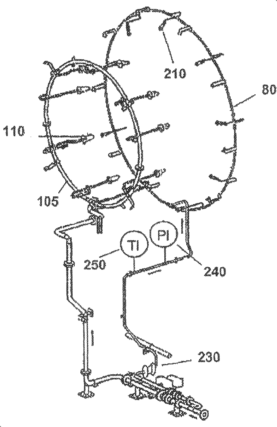
图4是图3的水洗系统的水歧管系统的透视图。部件表4 is a perspective view of the water manifold system of the water wash system of FIG. 3 . parts list
10 已知水洗系统10 Known water washing system
20 空气入口通道20 Air Inlet Channel
30 压缩机30 Compressor
40 喇叭口壳体40 Bell mouth shell
45 入口45 Entrance
50 入口压力通风系统50 Inlet plenum
60 喇叭口支柱60 Trumpet pillar
70 叶片70 blades
75 前歧管系统75 Front manifold system
80 后歧管系统80 rear manifold system
90 在线的后侧水洗喷嘴90 In-line rear side wash nozzles
100 在线的前侧水洗喷嘴100 in-line front side wash nozzles
105 脱机的歧管系统105 Off-Line Manifold System
110 脱机的水洗系统110 off-line washing system
115 上游喷嘴115 Upstream nozzle
200 水洗系统200 Water washing system
210 在线的后侧水洗系统210 Online rear side washing system
220 水滴喷雾220 Water Droplet Spray
230 压力调节阀230 Pressure regulating valve
240 局部压力表240 local pressure gauge
250 压力传感器250 pressure sensor
具体实施方式 Detailed ways
现在参考附图,其中相同的数字在多个附图中代表类似的元件。图1和图2显示了已知水洗系统10的示例。水洗系统10的喷嘴位于压缩机30的空气入口通道20的周围。一般地,压缩机30的空气入口通道20在与入口压力通风系统50连通的喇叭口壳体40形成。喇叭口壳体40包括入口压力通风系统50附近的入口45。空气入口通道20然后通过多个喇叭口支柱60,进入压缩机30的多个旋转叶片70。Referring now to the drawings, wherein like numerals represent similar elements throughout the several views. An example of a known
如图2所示,在线的水洗系统10包括多个单独的供应歧管,前歧管75和后歧管80。各歧管可向多个对应的喷嘴,多个后喷嘴90和多个前喷嘴100供水。这种机构类似于McDermott的美国专利No.5,011,540所显示的机构,该机构本文参考引用。水洗系统10整体上还可包括独立的歧管105和喷嘴110,用于离线水洗。其他上游喷嘴115也可用于本文的水洗系统。As shown in FIG. 2 , the in-line
如上所述,两组喷嘴90,100产生水滴喷雾,被旋转压缩机叶片70形成的负压吸入空气入口通道20。在沿空气入口通道20移动过程中,一些水滴撞击喇叭口壳体40的内侧壁和/或喇叭口支柱60。这些高度集中的水滴可撞击第一级旋转叶片70的根部。文中介绍的喷嘴90,100,115因此只提供了很小的目标固定能力,及低效的清洗,并可能对叶片70造成极大损坏。As mentioned above, the two sets of
图3和图4显示了本文介绍的水洗系统200。在该水洗系统200,取消了在线的前水洗喷嘴100,在线的后水洗喷嘴90进行了重新设计,移动到新位置。新的后喷嘴210位于已知水洗系统10的后侧喷嘴90的前述位置的下游。具体地,后侧喷嘴210位于喇叭口壳体40内空气入口通道20的周围,位于喇叭口支柱60之间。喷嘴210可安装在壳体40壁上加工出的孔中。喷嘴210的数量可等于或大于支柱60的数量,等于或大于支柱对的数量。各组的相邻支柱60之间可安装一个或多个喷嘴210。Figures 3 and 4 illustrate the water washing system 200 described herein. In this washing system 200, the online
喷嘴210位于已知的入口高速空气区,经过分析测试证实喷雾可有效地进入压缩机30的空气入口通道20。高速空气区的特性可通过空气入口通道20,入口压力通风系统50和喇叭口壳体40的空气动力学模型来确定。这样设置可减小对喇叭口壳体40壁和支柱60的润湿,减少到达第一级叶片70根部的水量。The
功能性地,后侧喷嘴210位于某位置周围,可提供目标控制能力于压缩机空气入口通道20内。高速入口空气流周围的该位置可形成优化水滴220喷雾方向的能力。优化的喷雾区域形成了喷雾水滴220的全径向分布,除了叶片70的根部外。实际目标控制能力涉及到喷嘴压力比、喷射角和喷嘴设计。如所指出的,大部分喷射水滴220保持在压缩机空气入口通道20的自由空气流通道内。Functionally, the
喷雾水滴220的尺寸和速度曲线都随着入口速度的变化而变化。入口空气速度直接涉及到压缩机30和入口空气通道20的几何形状,应针对各特定燃气涡轮机模型进行系统200最佳设计的分析和形成。可通过包括计算流体动力学(CFD)和实际尺寸风洞实验的系统模型,实现最佳设计。速度还可随着周围的操作条件,涡轮机载荷和其它操作参数进行变化。Both the size and the velocity profile of the spray droplets 220 vary with the inlet velocity. The inlet air velocity is directly related to the geometry of the
因供水压力成为喷嘴压力比的一个影响因素,系统200还可包括压力调节阀230和局部压力表240,以保证压力保持在希望的水平。也可使用压力传感器250。Since supply water pressure is a factor in the nozzle pressure ratio, system 200 may also include a
应当理解,前面的介绍只是涉及到本发明的优选实施例,其可进行许多的变化和改进,这未脱离如所附权利要求和其等效体所限定的本发明的基本精神和范围。It should be understood that the foregoing description only relates to the preferred embodiments of the invention, which are susceptible to many changes and modifications without departing from the basic spirit and scope of the invention as defined by the appended claims and their equivalents.
Claims (9)
Applications Claiming Priority (2)
| Application Number | Priority Date | Filing Date | Title |
|---|---|---|---|
| US11/161,469 US20070028947A1 (en) | 2005-08-04 | 2005-08-04 | Gas turbine on-line compressor water wash system |
| US11/161469 | 2005-08-04 |
Publications (2)
| Publication Number | Publication Date |
|---|---|
| CN1908383A CN1908383A (en) | 2007-02-07 |
| CN1908383B true CN1908383B (en) | 2011-11-09 |
Family
ID=36968967
Family Applications (1)
| Application Number | Title | Priority Date | Filing Date |
|---|---|---|---|
| CN2006101091840A Expired - Fee Related CN1908383B (en) | 2005-08-04 | 2006-08-04 | Gas turbine on-line compressor water wash system |
Country Status (4)
| Country | Link |
|---|---|
| US (1) | US20070028947A1 (en) |
| EP (1) | EP1749976B1 (en) |
| JP (1) | JP2007040307A (en) |
| CN (1) | CN1908383B (en) |
Families Citing this family (34)
| Publication number | Priority date | Publication date | Assignee | Title |
|---|---|---|---|---|
| US7571735B2 (en) * | 2006-09-29 | 2009-08-11 | Gas Turbine Efficiency Sweden Ab | Nozzle for online and offline washing of gas turbine compressors |
| EP1970133A1 (en) * | 2007-03-16 | 2008-09-17 | Lufthansa Technik AG | Device and method for cleaning the core engine of a turbojet engine |
| EP1972758A1 (en) * | 2007-03-19 | 2008-09-24 | ABB Turbo Systems AG | Turbine cleaning |
| EP2052792A3 (en) * | 2007-10-09 | 2011-06-22 | Gas Turbine Efficiency Sweden AB | Drain valve, washing system and sensing of rinse and wash completion |
| US8845819B2 (en) * | 2008-08-12 | 2014-09-30 | General Electric Company | System for reducing deposits on a compressor |
| CN101725410B (en) * | 2008-10-27 | 2011-09-07 | 上海电气电站设备有限公司 | Water washing device for gas turbine |
| US8381529B2 (en) * | 2009-01-29 | 2013-02-26 | General Electric Company | System and method for water injection in a turbine engine |
| US9016293B2 (en) * | 2009-08-21 | 2015-04-28 | Gas Turbine Efficiency Sweden Ab | Staged compressor water wash system |
| US8347900B2 (en) * | 2011-04-05 | 2013-01-08 | Jensen dustin | Wind turbine fluid application apparatus |
| EP2562430A1 (en) * | 2011-08-24 | 2013-02-27 | Siemens Aktiengesellschaft | Method for washing an axial compressor |
| US9023155B2 (en) | 2012-07-31 | 2015-05-05 | Ecoservices, Llc | Engine wash apparatus and method—manifold |
| FR3005108B1 (en) * | 2013-04-30 | 2018-01-05 | Safran Helicopter Engines | TURBOMACHINE AIR INTAKE CASTER WASHING DEVICE |
| US9951646B2 (en) | 2013-07-01 | 2018-04-24 | General Electric Company | Gas turbine on-line water wash system and method |
| FR3011035B1 (en) * | 2013-09-25 | 2015-10-09 | Snecma | EXHAUST CASE COMPRISING A FLUID EVACUATION DEVICE, AND TURBOMACHINE |
| EP3055532B1 (en) | 2013-10-10 | 2019-12-18 | EcoServices, LLC | Radial passage engine wash manifold |
| ITCO20130056A1 (en) * | 2013-11-04 | 2015-05-05 | Nuovo Pignone Srl | INTEGRATED WASHING SYSTEM FOR MOTOR WITH GAS TURBINE. |
| US9470105B2 (en) | 2013-11-21 | 2016-10-18 | General Electric Company | Automated water wash system for a gas turbine engine |
| ITMI20132042A1 (en) | 2013-12-06 | 2015-06-07 | Nuovo Pignone Srl | METHODS FOR WASHING MOTORS WITH GAS TURBINES AND GAS TURBINE ENGINES |
| ITCO20130064A1 (en) | 2013-12-06 | 2015-06-07 | Nuovo Pignone Srl | WASH NOZZLES AND MOTORS WITH GAS TURBINE |
| US20150354403A1 (en) * | 2014-06-05 | 2015-12-10 | General Electric Company | Off-line wash systems and methods for a gas turbine engine |
| JP2016061261A (en) * | 2014-09-19 | 2016-04-25 | 三菱重工業株式会社 | Centrifugal compressor |
| US20160169107A1 (en) * | 2014-12-12 | 2016-06-16 | General Electric Company | Systems and methods for injecting fluids at one or more stages of a multi-stage component |
| CN105457937B (en) * | 2015-12-29 | 2017-12-12 | 中国航空工业集团公司沈阳发动机设计研究所 | A kind of cleaning device of gas turbine runner elements |
| US10005111B2 (en) * | 2016-01-25 | 2018-06-26 | General Electric Company | Turbine engine cleaning systems and methods |
| US11313246B2 (en) * | 2016-11-30 | 2022-04-26 | General Electric Company | Gas turbine engine wash system |
| US10227891B2 (en) * | 2017-03-29 | 2019-03-12 | General Electric Company | Gas turbine engine wash system |
| US11022038B2 (en) * | 2017-05-04 | 2021-06-01 | General Electric Company | Compressor circumferential fluid distribution system |
| EP3444441B1 (en) * | 2017-08-14 | 2020-04-08 | General Electric Company | Gas turbine engine with inlet frame |
| US20190093505A1 (en) * | 2017-09-22 | 2019-03-28 | General Electric Company | Engine Wash Analytics |
| US11207716B2 (en) * | 2017-10-12 | 2021-12-28 | General Electric Company | Compressor water wash system |
| IT201800021067A1 (en) * | 2018-12-27 | 2020-06-27 | Nuovo Pignone Tecnologie Srl | STATOR AERODYNAMIC COMPONENTS WITH NOZZLES AND METHODS FOR CLEANING A TURBOMACHINE |
| CN111085521A (en) * | 2019-12-18 | 2020-05-01 | 沈阳鼓风机集团股份有限公司 | Cleaning device for centrifugal compressor impeller |
| CN111396339A (en) * | 2020-02-25 | 2020-07-10 | 浙江马尔风机有限公司 | Fan impeller cleaning device |
| US20250122833A1 (en) * | 2023-10-17 | 2025-04-17 | Ge Infrastructure Technology Llc | Airless sprint & water wash system |
Citations (2)
| Publication number | Priority date | Publication date | Assignee | Title |
|---|---|---|---|---|
| US5193976A (en) * | 1990-02-14 | 1993-03-16 | Turbotect Ag | Injection device for the on-line wet cleaning of compressors |
| CN1080022A (en) * | 1988-07-08 | 1993-12-29 | 陶氏化学公司 | The method and apparatus of the air of cleaning gas turbine inlet and the combustion gas turbine that uses this method and apparatus |
Family Cites Families (9)
| Publication number | Priority date | Publication date | Assignee | Title |
|---|---|---|---|---|
| US2874537A (en) * | 1955-01-07 | 1959-02-24 | Martin Co | Turbojet engine arrangement utilizing evaporative cooling |
| US4196020A (en) * | 1978-11-15 | 1980-04-01 | Avco Corporation | Removable wash spray apparatus for gas turbine engine |
| US5011540A (en) * | 1986-12-24 | 1991-04-30 | Mcdermott Peter | Method and apparatus for cleaning a gas turbine engine |
| JP2000274206A (en) * | 1999-03-24 | 2000-10-03 | Hitachi Ltd | gas turbine |
| US6553768B1 (en) * | 2000-11-01 | 2003-04-29 | General Electric Company | Combined water-wash and wet-compression system for a gas turbine compressor and related method |
| US6630198B2 (en) * | 2001-01-19 | 2003-10-07 | General Electric Co. | Methods and apparatus for washing gas turbine engines |
| US6920749B2 (en) * | 2002-03-15 | 2005-07-26 | Parker-Hannifin Corporation | Multi-function simplex/prefilmer nozzle |
| SE522132C2 (en) * | 2002-12-13 | 2004-01-13 | Gas Turbine Efficiency Ab | Cleaning method for stationary gas turbine unit in operation, by spraying cleaning fluid into point in air inlet channel where air velocity has specific minimum value |
| SE525924C2 (en) * | 2003-09-25 | 2005-05-24 | Gas Turbine Efficiency Ab | Nozzle and method for cleaning gas turbine compressors |
-
2005
- 2005-08-04 US US11/161,469 patent/US20070028947A1/en not_active Abandoned
-
2006
- 2006-07-27 EP EP06253911A patent/EP1749976B1/en not_active Not-in-force
- 2006-08-03 JP JP2006211658A patent/JP2007040307A/en not_active Ceased
- 2006-08-04 CN CN2006101091840A patent/CN1908383B/en not_active Expired - Fee Related
Patent Citations (2)
| Publication number | Priority date | Publication date | Assignee | Title |
|---|---|---|---|---|
| CN1080022A (en) * | 1988-07-08 | 1993-12-29 | 陶氏化学公司 | The method and apparatus of the air of cleaning gas turbine inlet and the combustion gas turbine that uses this method and apparatus |
| US5193976A (en) * | 1990-02-14 | 1993-03-16 | Turbotect Ag | Injection device for the on-line wet cleaning of compressors |
Also Published As
| Publication number | Publication date |
|---|---|
| JP2007040307A (en) | 2007-02-15 |
| US20070028947A1 (en) | 2007-02-08 |
| EP1749976B1 (en) | 2012-04-18 |
| EP1749976A3 (en) | 2008-07-23 |
| CN1908383A (en) | 2007-02-07 |
| EP1749976A2 (en) | 2007-02-07 |
Similar Documents
| Publication | Publication Date | Title |
|---|---|---|
| CN1908383B (en) | Gas turbine on-line compressor water wash system | |
| US20090320440A1 (en) | Wet compression systems in turbine engines | |
| CN114000922B (en) | Engine component with cooling holes | |
| US8834649B2 (en) | System for reducing deposits on a compressor | |
| US7963095B2 (en) | Inlet air conditioning system | |
| US7712301B1 (en) | System and method for augmenting turbine power output | |
| CN104653296B (en) | Automation water wash system for gas-turbine unit | |
| CN107084004B (en) | Impact holes for turbine engine components | |
| MXPA06009305A (en) | Method and apparatus for cleaning a turbofan gas turbine engine. | |
| WO1997043530A1 (en) | Process and apparatus for achieving power augmentation in gas turbines via wet compression | |
| US20100135822A1 (en) | Turbine blade for a gas turbine engine | |
| JP2011506821A (en) | Turbine and method for cleaning turbine blades in operating condition | |
| KR20140012095A (en) | Unflared compressor blade | |
| CN103732862B (en) | Rotor seal line groove is repaired | |
| EP3667027B1 (en) | Vane ring for a gas turbine engine and associated method | |
| EP3978150B1 (en) | System and method for cleaning deposit from a component of an assembled, on-wing gas turbine engine | |
| US8628297B2 (en) | Tip flowpath contour | |
| US10815788B2 (en) | Turbine blade with slot film cooling | |
| JP2016061291A (en) | Method and system for protecting surfaces from corrosive contaminants | |
| US20120045324A1 (en) | Hub flowpath contour | |
| US10968771B2 (en) | Method and system for ice tolerant bleed takeoff | |
| US20220389834A1 (en) | Systems for treating an installed and assembled gas turbine engine | |
| EP3667026A1 (en) | Extension air feed hole blockage preventer for a gas turbine engine | |
| US20130115867A1 (en) | Enclosure system and method for applying coating | |
| US20200190993A1 (en) | Shape recessed surface cooling air feed hole blockage preventer for a gas turbine engine |
Legal Events
| Date | Code | Title | Description |
|---|---|---|---|
| C06 | Publication | ||
| PB01 | Publication | ||
| C10 | Entry into substantive examination | ||
| SE01 | Entry into force of request for substantive examination | ||
| C14 | Grant of patent or utility model | ||
| GR01 | Patent grant | ||
| C17 | Cessation of patent right | ||
| CF01 | Termination of patent right due to non-payment of annual fee |
Granted publication date: 20111109 Termination date: 20130804 |