CN1908452A - Fluid booster - Google Patents
Fluid booster Download PDFInfo
- Publication number
- CN1908452A CN1908452A CN 200510089060 CN200510089060A CN1908452A CN 1908452 A CN1908452 A CN 1908452A CN 200510089060 CN200510089060 CN 200510089060 CN 200510089060 A CN200510089060 A CN 200510089060A CN 1908452 A CN1908452 A CN 1908452A
- Authority
- CN
- China
- Prior art keywords
- input
- channel
- piston
- piston cylinder
- input piston
- Prior art date
- Legal status (The legal status is an assumption and is not a legal conclusion. Google has not performed a legal analysis and makes no representation as to the accuracy of the status listed.)
- Granted
Links
Images


Landscapes
- Fluid-Pressure Circuits (AREA)
Abstract
本发明涉及一种流体增压器,包括连接在输入流道和输出流道之间的输入活塞缸和输出活塞缸,输入活塞与输出活塞通过活塞杆固定连接,且输入活塞面积大于输出活塞面积,于输入流道和输入活塞缸之间连接有双稳射流元件,该双稳射流元件包括可附壁切换的第一和第二切换流道以及排液口,其中第一切换流道连通于输入活塞缸的上腔,所述输入活塞缸的下腔通过一换向机构连通于第二切换流道或者连通于一泄流通道,所述的排液口通过节流元件连通于该泄流通道,节流元件与排液口之间的流道形成为节流支路,所述输出活塞缸的下腔通过单向导通元件连通于该节流支路。本发明适用于管道式和安装空间限制的场所。应用在石油钻井中,可对钻井液增压,用于提高井底喷射压力,从而提高钻井速度。
The invention relates to a fluid booster, which comprises an input piston cylinder and an output piston cylinder connected between the input flow channel and the output flow channel, the input piston and the output piston are fixedly connected by a piston rod, and the area of the input piston is larger than the area of the output piston , a bistable jet element is connected between the input flow channel and the input piston cylinder, and the bistable jet element includes first and second switching flow channels and a liquid discharge port that can be switched with the wall, wherein the first switching flow channel communicates with the The upper cavity of the input piston cylinder, the lower cavity of the input piston cylinder is communicated with the second switching channel or a drain channel through a reversing mechanism, and the drain port is communicated with the drain channel through a throttling element The flow channel between the throttling element and the liquid discharge port is formed as a throttling branch, and the lower chamber of the output piston cylinder communicates with the throttling branch through a one-way conducting element. The present invention is applicable to places with pipeline type and limited installation space. Applied in oil drilling, it can pressurize the drilling fluid to increase the injection pressure at the bottom of the well, thereby increasing the drilling speed.
Description
技术领域technical field
本发明涉及一种增压装置,具体地讲是一种流体增压器。The invention relates to a supercharging device, in particular to a fluid supercharger.
背景技术Background technique
流体增压装置是广泛应用于液压或者气压系统中给工作流体进行增压的装置。高压射流增压装置就是一种流体增压器,其一般是应用齿轮泵、活塞泵和柱塞泵,采用多路换向阀和逻辑控制阀组合来实现增压效果。该些增压装置的动力来源集中在机械驱动,并且配套设备的尺寸庞大,不适用于管式和安装空间受限制的场所。例如,在地质钻探、石油钻井和孔洞掘进等施工中,应用现有的高压射流作业设备收到约束。A fluid booster device is a device widely used in hydraulic or pneumatic systems to boost working fluid. The high-pressure jet booster is a fluid booster, which generally uses gear pumps, piston pumps and plunger pumps, and uses a combination of multi-way reversing valves and logic control valves to achieve boosting effects. The power sources of these supercharging devices are concentrated in mechanical drives, and the size of the supporting equipment is huge, so they are not suitable for places with limited pipe type and installation space. For example, in constructions such as geological drilling, oil drilling and hole excavation, the application of existing high-pressure jet operation equipment is restricted.
目前石油钻井的方法是钻头旋转以实现机械齿破岩,其中石油钻井的速度与钻井泵的泵压密切相关。试验表明,进一步提高泵压,可以大大提高钻井速度。但是从设备方便考虑,钻井泵压的大幅提高,不仅钻井泵本身技术上存在难于克服的困难,而且泵的地面管汇和钻柱系统也承受不了,并且其中还要涉及到整套钻井设备传动系统的重新设计和研制问题,因此就目前工艺条件来看比较难以实现。The current oil drilling method is to rotate the drill bit to break rock with mechanical teeth, and the speed of oil drilling is closely related to the pump pressure of the drilling pump. Tests have shown that further increasing the pump pressure can greatly increase the drilling speed. However, considering the convenience of equipment, the substantial increase in drilling pump pressure not only presents insurmountable technical difficulties in the drilling pump itself, but also cannot withstand the ground manifold and drill string system of the pump, and the entire drilling equipment transmission system is also involved. Therefore, it is difficult to realize in terms of current technological conditions.
因此,有必要提供一种设备尺寸小,可适用于管道式和安装空间受限制场所的流体增压器,来解决现有增压装置存在的上述缺陷。Therefore, it is necessary to provide a fluid booster that is small in size and applicable to pipelines and places with limited installation space, so as to solve the above-mentioned defects in existing boosting devices.
发明内容Contents of the invention
本发明所要解决的技术问题在于,提供一种流体增压器,其可适用于管道式和安装空间限制的场所,尤其适用于安装在钻井钻头上,用于提高井底喷射压力,从而提高钻井速度。The technical problem to be solved by the present invention is to provide a fluid booster, which can be used in pipeline-type and places with limited installation space, especially suitable for installation on drilling bits to increase the injection pressure at the bottom of the well, thereby improving the efficiency of drilling. speed.
本发明的上述技术问题可采用如下技术方案来解决,一种流体增压器,包括连接在输入流道和输出流道之间的输入活塞缸和输出活塞缸,输入活塞与输出活塞通过活塞杆固定连接,且输入活塞面积大于输出活塞面积,其特征在于,于输入流道和输入活塞缸之间连接有双稳射流元件,该双稳射流元件包括可附壁切换的第一和第二切换流道以及排液口,其中第一切换流道连通于输入活塞缸的上腔,所述输入活塞缸的下腔通过一换向机构连通于第二切换流道或者连通于一泄流通道,所述的排液口通过节流元件连通于该泄流通道,节流元件与排液口之间的流道形成为节流支路,所述输出活塞缸的下腔通过单向导通元件连通于该节流支路。The above-mentioned technical problems of the present invention can be solved by adopting the following technical solutions. A fluid booster includes an input piston cylinder and an output piston cylinder connected between the input flow channel and the output flow channel. The input piston and the output piston are connected through the piston rod It is fixedly connected, and the area of the input piston is larger than the area of the output piston. It is characterized in that a bistable jet element is connected between the input flow channel and the input piston cylinder. Flow passages and liquid discharge ports, wherein the first switching flow passage communicates with the upper chamber of the input piston cylinder, and the lower chamber of the input piston cylinder communicates with the second switching passage through a reversing mechanism or communicates with a discharge passage, The drain port is connected to the discharge channel through a throttling element, and the flow channel between the throttling element and the drain port is formed as a throttling branch, and the lower chamber of the output piston cylinder is communicated with through a one-way conducting element. in the throttling branch.
本发明中所采用的双稳射流元件,是利用射流的附壁效应而制成一种常用射流元件。该双稳射流元件的形状一般是完全对称的,其可由于附壁切换而导致射流在任一侧壁面上附着并稳定流动。根据双稳射流元件所具有的附壁和切换特性,该双稳射流元件可在两切换流道的压力发生变化时进行切换,附着于压力较小的切换流道中进行稳定流动。The bistable jet element used in the present invention is a commonly used jet element made by utilizing the Coanda effect of the jet. The shape of the bistable jet element is generally completely symmetrical, which can cause the jet to adhere to any side wall surface and flow stably due to the Coanda switch. According to the wall attachment and switching characteristics of the bistable jet element, the bistable jet element can be switched when the pressure of the two switching channels changes, and can be attached to the switching channel with a lower pressure for stable flow.
在本发明中,所述的输入活塞缸可为两个或者两个以上活塞缸相串联而成,相邻活塞之间通过活塞杆连接,该些活塞缸的下腔相连通。In the present invention, the input piston cylinder may be formed by connecting two or more piston cylinders in series, adjacent pistons are connected by piston rods, and the lower chambers of these piston cylinders are connected.
作为一个具体的例子,所述的活塞杆可为空心结构,该些活塞缸的下腔通过空心活塞杆相连通。As a specific example, the piston rod may be a hollow structure, and the lower chambers of the piston cylinders are connected through the hollow piston rod.
在本发明中,可进一步在输入流道上并联有溢流支路,以便于在输入流道的流量发生过高时,可通过该溢流支路分流,从而适应输入流道的流量变化。In the present invention, an overflow branch can be further connected in parallel on the input flow channel, so that when the flow rate of the input flow channel is too high, the flow can be shunted through the overflow branch, thereby adapting to the change of the flow rate of the input flow channel.
上述的溢流支路为通过溢流阀连通于泄流通道的支路。The overflow branch mentioned above is a branch connected to the discharge channel through the overflow valve.
作为另外一个可选择的例子,所述的溢流支路为直接连通于节流支路的支路。As another optional example, the overflow branch is a branch directly connected to the throttling branch.
在本发明中,所述的换向机构为二位三通换向阀,该二位三通阀受控在所述输入活塞缸的下腔在连通于第二切换流道的位置或者连通于一泄流通道的位置之间切换。In the present invention, the reversing mechanism is a two-position three-way reversing valve, and the two-position three-way valve is controlled when the lower chamber of the input piston cylinder communicates with the second switching channel or communicates with the Switch between the positions of a bleed channel.
作为一个具体的例子,所述的换向机构为二位三通换向滑阀,包括固定于输入活塞缸下腔中的阀套和滑动设置于该阀套中的阀芯,可通过阀芯在阀套中的滑动,而在两个位置之间切换。As a specific example, the reversing mechanism is a two-position three-way reversing slide valve, which includes a valve sleeve fixed in the lower chamber of the input piston cylinder and a spool slidingly arranged in the valve sleeve, which can pass through the spool Slide in the sleeve to switch between two positions.
进一步,所述的阀芯具有突出于阀套的抵顶部,在输入活塞的活塞杆上位于该阀芯的上方和下方分别对应设有与该抵顶部相配合而推动该抵顶部滑动的抵顶面,从而在输入活塞运动到抵顶面与阀芯相接触的位置时,通过该抵顶面推动阀芯滑动,从而使换向机构换向。Further, the spool has an abutment that protrudes from the valve sleeve, and the piston rod of the input piston is located above and below the spool and respectively provided with an abutment that cooperates with the abutment to push the abutment to slide. surface, so that when the input piston moves to the position where the abutment surface is in contact with the spool, the abutment surface pushes the spool to slide, thereby reversing the reversing mechanism.
本发明的流体增压器,由于采用双稳射流元件,结构简单、体积小,可满足较小作业空间对射流增压的要求。尤其是本发明的流体增压器可应用于石油钻井中,该流体增压器可安装在井底对部分循环钻井液进行增压输出,使得输出高压射流对井底岩石产生切割破碎,提高钻井破岩的综合效率,加快钻井速度。The fluid booster of the present invention adopts a bistable jet element, has a simple structure and a small volume, and can meet the requirement for jet boosting in a small working space. In particular, the fluid booster of the present invention can be applied to oil drilling. The fluid booster can be installed at the bottom of the well to pressurize and output part of the circulating drilling fluid, so that the output high-pressure jet can cut and break the rock at the bottom of the well, improving the drilling efficiency. The overall efficiency of rock breaking increases the drilling speed.
附图说明Description of drawings
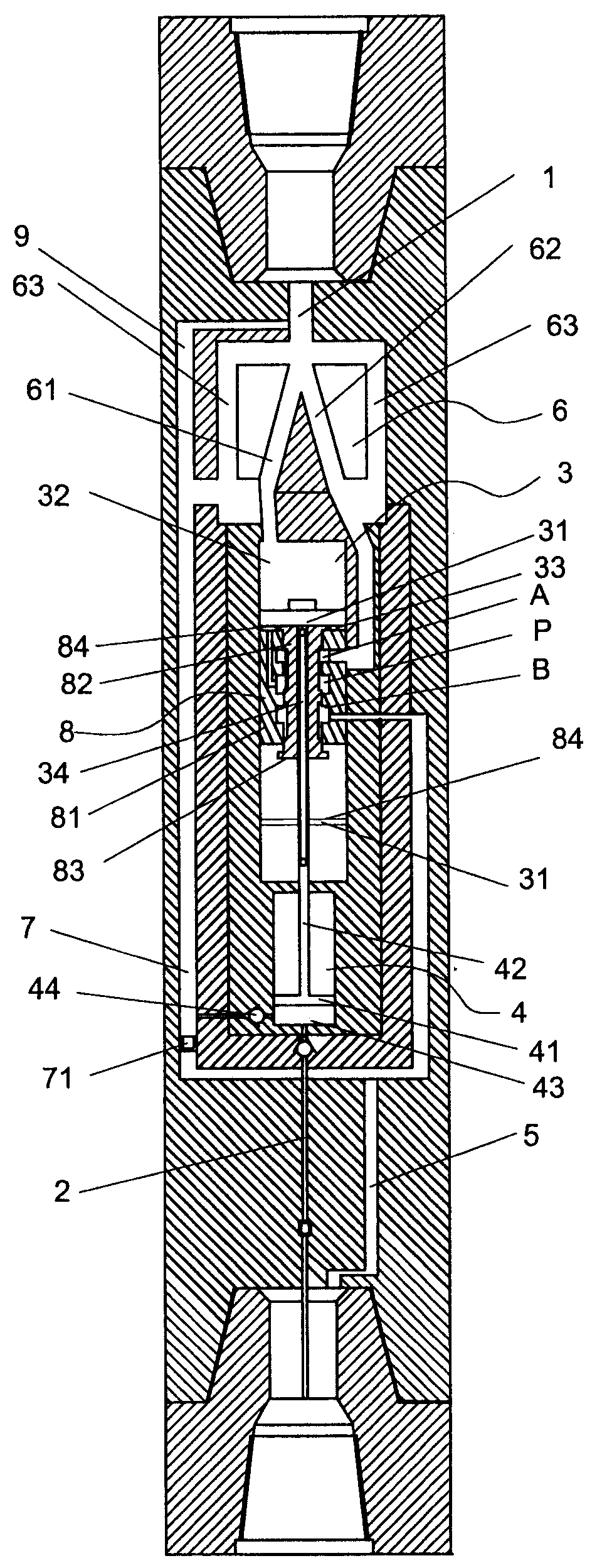
图1本发明的流体增压器的一种实施结构示意图;A kind of implementation structure schematic diagram of Fig. 1 fluid supercharger of the present invention;
图2本发明的流体增压器活塞处于上位时的结构示意图;Fig. 2 is a schematic structural view of the fluid booster piston of the present invention when it is in the upper position;
图3本发明的流体增压器活塞处于下位的结构示意图;Fig. 3 is a structural schematic diagram of the fluid booster piston in the lower position of the present invention;
图4本发明的流体增压器的再一种实施结构示意图。Fig. 4 is a structural schematic diagram of yet another implementation of the fluid booster of the present invention.
具体实施方式Detailed ways
如图1-4所示,本发明的流体增压器,包括连接在输入流道1和输出流道2之间的输入活塞缸3和输出活塞缸4,输入活塞31与输出活塞41通过活塞杆42固定连接,且输入活塞31的面积大于输出活塞41的面积,于输入流道1和输入活塞缸3之间连接有双稳射流元件6,该双稳射流元件6包括可附壁切换的第一和第二切换流道61、62以及排液口63,其中第一切换流道61连通于输入活塞缸3的上腔32,输入活塞缸3的下腔33通过一换向机构连通于第二切换流道62或者连通于一泄流通道5,所述的排液口63通过节流元件71连通于该泄流通道5,节流元件71与排液口63之间的流道形成为节流支路7,所述输出活塞缸4的下腔43通过单向导通元件44连通于该节流支路7。As shown in Figures 1-4, the fluid booster of the present invention includes an
这样,如图2所示,假定输入活塞31位于活塞缸3的上位(即上死点),此时换向机构受控使输入活塞缸3的下腔33与第二切换流道62的连通通道关闭而打开输入活塞缸3的下腔33与泄流通道5的连通通道,此时双稳射流元件的第二切换流道62受背压的影响,流体压力增大,使流体附壁于第一切换流道61一侧,并通过该第一切换流道61进入输入活塞缸3的上腔32,同时由于节流元件71的作用,使与节流之路7连通的第一切换流道61中的流体压力大于连通于泄流通道5的输入活塞缸3下腔33中的流体压力,从而输入活塞31在该压差作用下向下运动,同时带动输出活塞缸4的输出活塞41向下运动,输出活塞缸4中的流体通过输出流道2高压射流输出,而输入活塞缸3下腔33中的流体通过泄流通道5泄流。如图3所示,当输入活塞缸3的输入活塞31运动到下位(即下死点)时,换向机构受控换向,使输入活塞缸3的下腔33与泄流通道5的连通通道关闭而打开输入活塞缸3的下腔33与第二切换流道62的连通通道,此时输入活塞缸3的上腔32在背压作用下压力增大,使与上腔32连通的第一切换流道61压力增加,输入流道1输入的流体附壁切换到第二切换流道62,并通过该第二切换流道62流入输入活塞缸3的下腔33中,在下腔33和上腔32流体动压差作用下,推动输入活塞31向上运动,输出活塞缸4的输出活塞41随之向上运动,输出活塞缸4的下腔43同时通过单向导通元件44补入工作流体,当输入活塞31运动到上位(即上死点)时,换向机构受控换向,使输入活塞缸3的下腔33与第二切换流道62的连通通道关闭而打开输入活塞缸3的下腔33与泄流通道5的连通通道,开始下一个高压射流输出循环。Like this, as shown in Figure 2, suppose
在本发明的上述流体增压过程中,由于是采用射流元件的附壁切换特性,并结合换向机构的换向以及节流元件71的压差作用来实现输入活塞31上下运动的切换的,与现有应用机械驱动泵并采用多路换向阀和逻辑控制阀组合来实现增压的增压装置相比,结构简单、体积小,可满足较小作业空间对射流增压的要求。In the above-mentioned fluid pressurization process of the present invention, since the wall-attached switching characteristics of the jet element are used, combined with the reversing of the reversing mechanism and the pressure difference of the
尤其是如图4所示,本发明的流体增压器可通过上下接头连接安装于井底的钻头上而应用于石油钻井中,此时工作流体为钻井液,该流体增压器可在井底对部分循环钻井液进行增压,并输出到钻头喷嘴,使得输出的高压射流对井底岩石产生切割破碎,从而提高钻井破岩的综合效率,加快钻井速度。Especially as shown in Figure 4, the fluid booster of the present invention can be installed on the drill bit at the bottom of the well by connecting the upper and lower joints and applied in oil drilling. The bottom pressurizes part of the circulating drilling fluid and outputs it to the nozzle of the drill bit, so that the output high-pressure jet can cut and break the rock at the bottom of the well, thereby improving the overall efficiency of drilling and breaking rock and accelerating the drilling speed.
如图1-4所示,在本发明中,所述的输入活塞缸3可为两个或者两个以上活塞缸相串联而成,相邻活塞31之间通过活塞杆34相连接,并且该些活塞缸的下腔33相连通,这样可在不增加流体增压器截面积的情况下,增大输入活塞31的总面积,从而增加增压比,并且更适应于在空间比较狭小的管道中。该活塞缸串联的个数可根据所需的增压比以及每个活塞的面积而确定,在本实施例的附图中仅以两个活塞缸串联为例进行了图示,两个以上活塞缸串联的例子与其相类似,不再一一举例。As shown in Figures 1-4, in the present invention, the
如图1-4所示,作为一个具体的例子,所述的活塞杆34可为空心结构,该些活塞缸的下腔33通过空心活塞杆34相连通。As shown in FIGS. 1-4 , as a specific example, the
如图4所示,在本发明中,可进一步在输入流道上并联有溢流支路9,以便于在输入流道1的流量发生过高时,可通过该溢流支路9分流,从而适应输入流道1的流量变化。As shown in Figure 4, in the present invention, an
上述的溢流支路9可为通过溢流阀连通于泄流通道5的支路,图中未示出,其中的溢流量可通过设定溢流阀的开启压力来确定。The
作为另外一个可选择的例子,如图4所示,所述的溢流支路9为直接连通于节流支路7的支路,这样当输入流道1中的流量过高时,一部分流体可通过溢流支路7分流后,经节流支路7后,进入泄流通道5泄流。As another optional example, as shown in Figure 4, the
在本发明中,如图1-4所示,所述的换向机构可为二位三通换向阀8,该二位三通阀8受控在所述输入活塞缸3的下腔33连通于第二切换流道62的位置或者连通于泄流通道5的位置之间切换。如图1-4所示,该二位三通换向阀8可具体具有连通口A、P、B,其中连通口A连通于第二切换流道62,连通口P连通于输入活塞缸3的下腔33,而连通口B连通于泄流通道5,该换向阀8受控进行换向,使连通口P与连通口A或者连通口B连通,从而实现在所述输入活塞缸3的下腔33连通于第二切换流道62的位置或者连通于泄流通道5的位置之间切换。In the present invention, as shown in Figures 1-4, the reversing mechanism can be a two-position three-
该二位三通换向阀8可为行程控制阀,通过活塞运动的不同位置控制该二位三通换向阀8在不同位置之间的切换。The two-position three-
该二位三通换向滑阀的阀芯82的滑动控制可通过输入活塞31的上下运动位置来自动控制。作为一个通过输入活塞31的上下位置自动控制的具体例子,所述的阀芯82具有突出于阀套81的抵顶部83,在输入活塞31的活塞杆上位于该阀芯82的上方和下方分别对应设有与该抵顶部83相配合而推动该抵顶部83滑动的抵顶面84,从而在输入活塞31运动到抵顶面84与阀芯82相接触的位置时,通过该抵顶面84推动阀芯82滑动,从而使换向机构换向。The sliding control of the
在本实施例以两个活塞缸串联而成输入活塞缸3的例子中,该上下抵顶面84可分别由第一级输入活塞31的下表面和第二级输入活塞31的上表面构成。In this embodiment, where two piston cylinders are connected in series to form the
这样,如图2所示,在输入活塞31处于上位时,第二级串联输入活塞31抵顶于阀套81下部,将抵顶部83推入阀套81中,使换向阀8换向到输入活塞缸3的下腔33与第二切换流道62的连通通道关闭而输入活塞缸3的下腔33与泄流通道5的连通通道打开的位置,而当输入活塞31处于下位时,第一级输入活塞31抵顶于阀套81上部,将抵顶部83推入阀套81中,使换向阀8换向到输入活塞缸3的下腔33与泄流通道5的连通通道关闭而输入活塞缸3的下腔33与第二切换流道62的连通通道打开的位置。采用该结构,换向阀8的换向通过输入活塞31的抵顶而在输入活塞31处于上位和下位自动在两个位置之间进行换向,从而省略了现有的复杂换向控制结构,使本发明流体增压器的结构更为简单。In this way, as shown in Figure 2, when the
上述实施例为本发明的几个具体实施方式,仅用于说明本发明而非用于限制本发明。例如,本发明的流体增压器除了可应用于石油钻井中的例子外,还可应用其他如孔洞挖掘、高压射流切割等的流体增压技术中。The above examples are several specific implementations of the present invention, and are only used to illustrate the present invention rather than limit the present invention. For example, the fluid booster of the present invention can also be applied to other fluid boosting technologies such as hole excavation, high-pressure jet cutting, etc., in addition to the examples in oil drilling.
Claims (9)
Priority Applications (1)
| Application Number | Priority Date | Filing Date | Title |
|---|---|---|---|
| CNB2005100890606A CN100510427C (en) | 2005-08-03 | 2005-08-03 | Fluid booster |
Applications Claiming Priority (1)
| Application Number | Priority Date | Filing Date | Title |
|---|---|---|---|
| CNB2005100890606A CN100510427C (en) | 2005-08-03 | 2005-08-03 | Fluid booster |
Publications (2)
| Publication Number | Publication Date |
|---|---|
| CN1908452A true CN1908452A (en) | 2007-02-07 |
| CN100510427C CN100510427C (en) | 2009-07-08 |
Family
ID=37699641
Family Applications (1)
| Application Number | Title | Priority Date | Filing Date |
|---|---|---|---|
| CNB2005100890606A Expired - Fee Related CN100510427C (en) | 2005-08-03 | 2005-08-03 | Fluid booster |
Country Status (1)
| Country | Link |
|---|---|
| CN (1) | CN100510427C (en) |
Cited By (2)
| Publication number | Priority date | Publication date | Assignee | Title |
|---|---|---|---|---|
| CN113236158A (en) * | 2021-04-19 | 2021-08-10 | 中煤科工集团淮北爆破技术研究院有限公司 | In-hole booster for high-pressure jet auxiliary drilling and working method thereof |
| CN117646750A (en) * | 2023-10-20 | 2024-03-05 | 河北尚泰合力液压元件有限公司 | Roofbolter and hydraulic propulsion system thereof |
-
2005
- 2005-08-03 CN CNB2005100890606A patent/CN100510427C/en not_active Expired - Fee Related
Cited By (2)
| Publication number | Priority date | Publication date | Assignee | Title |
|---|---|---|---|---|
| CN113236158A (en) * | 2021-04-19 | 2021-08-10 | 中煤科工集团淮北爆破技术研究院有限公司 | In-hole booster for high-pressure jet auxiliary drilling and working method thereof |
| CN117646750A (en) * | 2023-10-20 | 2024-03-05 | 河北尚泰合力液压元件有限公司 | Roofbolter and hydraulic propulsion system thereof |
Also Published As
| Publication number | Publication date |
|---|---|
| CN100510427C (en) | 2009-07-08 |
Similar Documents
| Publication | Publication Date | Title |
|---|---|---|
| CN101666339B (en) | hydraulic booster | |
| CN106870317B (en) | A hydraulically driven double-acting mud pump | |
| CN102108847A (en) | Dual well balance type hydraulic pumping unit and working method thereof | |
| US6651749B1 (en) | Well tool actuators and method | |
| CN201037377Y (en) | Horizontal positioning drilling machine valve control interflow speeding up hydraulic system | |
| CN115405578A (en) | Micro-angle stepping control method for hydraulic motor | |
| CN2821204Y (en) | Fluid supercharger | |
| CN104500399B (en) | The structure of compressor slide valve position control | |
| CN1950615A (en) | Innerscoping hydraulic system | |
| CN1908452A (en) | Fluid booster | |
| CN101078396A (en) | Differential pressure drive reciprocating double-action booster pump | |
| CN204266988U (en) | A kind of pilot-controlled switch sliding sleeve | |
| CN217873519U (en) | Micro-angle stepping control valve set of hydraulic motor | |
| CN208184711U (en) | A kind of intelligent control ball injector and hydraulic control valve | |
| CN117468899A (en) | Find stifled water oil recovery integrated tubular column under oil well production state | |
| CN117646640A (en) | Hydraulic support electrohydraulic proportional control system and method based on independent pilot liquid supply valve | |
| CN205876288U (en) | A multifunctional fracturing manifold | |
| CN204284037U (en) | A kind of hydraulic system, pumping system and concrete pumping equipment | |
| CN204716201U (en) | A kind of pilot-controlled switch sliding sleeve | |
| CN202326059U (en) | Double-acting pressurizing gas-liquid composite pump | |
| CN102410170B (en) | Double-acting supercharging gas-liquid combination pump | |
| CN115978021B (en) | A mechanical hydraulic reversing circuit and reversing method for a rotary cylinder | |
| CN2672344Y (en) | Liquid control throttle oil changing valve | |
| CN108730145A (en) | A kind of hydraulic slurry pump | |
| CN219605692U (en) | Novel back pressure valve for tunnel drilling machine |
Legal Events
| Date | Code | Title | Description |
|---|---|---|---|
| C06 | Publication | ||
| PB01 | Publication | ||
| C10 | Entry into substantive examination | ||
| SE01 | Entry into force of request for substantive examination | ||
| C14 | Grant of patent or utility model | ||
| GR01 | Patent grant | ||
| C17 | Cessation of patent right | ||
| CF01 | Termination of patent right due to non-payment of annual fee |
Granted publication date: 20090708 Termination date: 20120803 |