CN1909314A - Electronic trip device with a power supply circuit means, and circuit breaker comprising such device - Google Patents
Electronic trip device with a power supply circuit means, and circuit breaker comprising such device Download PDFInfo
- Publication number
- CN1909314A CN1909314A CNA200610108217XA CN200610108217A CN1909314A CN 1909314 A CN1909314 A CN 1909314A CN A200610108217X A CNA200610108217X A CN A200610108217XA CN 200610108217 A CN200610108217 A CN 200610108217A CN 1909314 A CN1909314 A CN 1909314A
- Authority
- CN
- China
- Prior art keywords
- voltage
- supply
- electronic
- processing unit
- storage capacitor
- Prior art date
- Legal status (The legal status is an assumption and is not a legal conclusion. Google has not performed a legal analysis and makes no representation as to the accuracy of the status listed.)
- Granted
Links
Images


Classifications
-
- H—ELECTRICITY
- H02—GENERATION; CONVERSION OR DISTRIBUTION OF ELECTRIC POWER
- H02H—EMERGENCY PROTECTIVE CIRCUIT ARRANGEMENTS
- H02H1/00—Details of emergency protective circuit arrangements
- H02H1/06—Arrangements for supplying operative power
- H02H1/063—Arrangements for supplying operative power primary power being supplied by fault current
-
- H—ELECTRICITY
- H01—ELECTRIC ELEMENTS
- H01H—ELECTRIC SWITCHES; RELAYS; SELECTORS; EMERGENCY PROTECTIVE DEVICES
- H01H71/00—Details of the protective switches or relays covered by groups H01H73/00 - H01H83/00
- H01H71/10—Operating or release mechanisms
- H01H71/12—Automatic release mechanisms with or without manual release
- H01H71/123—Automatic release mechanisms with or without manual release using a solid-state trip unit
Landscapes
- Emergency Protection Circuit Devices (AREA)
- Breakers (AREA)
- Direct Current Feeding And Distribution (AREA)
- Driving Mechanisms And Operating Circuits Of Arc-Extinguishing High-Tension Switches (AREA)
- Keying Circuit Devices (AREA)
Abstract
电子断开装置包含至少一个电流传感器(T1,T2,T3);提供电源电流(Ia)的整流电路(3);控制设计成动作主导线(1)的断开机构的操作机构的电子处理单元(6);和装备有设计成将电源电压(VA)提供给电子处理单元的电压调节器(17)的电源电路(4)。在电子断开装置中,电源电路包含使升高电压(VB)提供给设计成将电源电压(VA)提供给电子处理单元的电压调节器(17)的输入端的升压装置(19,20),所述升高电压(VB)大于存储电容器两端的电压(VM)。本发明还涉及装备有上述电子断开装置的断路器。
The electronic disconnecting device comprises at least one current sensor (T1, T2, T3); a rectification circuit (3) supplying the supply current (Ia); an electronic processing unit controlling the operating mechanism of the disconnecting mechanism designed to operate the main conductor (1) (6); and a power supply circuit (4) equipped with a voltage regulator (17) designed to supply a supply voltage (VA) to the electronic processing unit. In an electronic disconnect device, the power supply circuit comprises boosting means (19, 20) for supplying a boosted voltage (VB) to an input of a voltage regulator (17) designed to supply a supply voltage (VA) to an electronic processing unit , the boosted voltage (VB) is greater than the voltage across the storage capacitor (VM). The invention also relates to a circuit breaker equipped with an electronic disconnecting device as described above.
Description
技术领域technical field
本发明涉及断路器的领域,尤其涉及装备这些电子断开装置的断路器。The present invention relates to the field of circuit breakers, and in particular to circuit breakers equipped with these electronic disconnecting devices.
本发明尤其涉及用于断路器的电子断开装置,所述断开装置包含:In particular the invention relates to an electronic disconnecting device for a circuit breaker, said disconnecting device comprising:
-提供代表所述断路器的主导线中的初级电流的次级电流的至少一个电流传感器;- at least one current sensor providing a secondary current representative of the primary current in the main conductor of said circuit breaker;
-整流所述次级电流和提供电源电流的整流电路;- a rectification circuit for rectifying said secondary current and providing supply current;
-控制设计成动作主导线的断开机构的操作机构的电子处理单元;和- the electronic processing unit controlling the operating mechanism of the disconnecting mechanism designed to act on the main lead; and
-电源电路,装备有设计成向操作机构提供电源的存储电容器和设计成将电源电压提供给电子处理单元的电压调节器,所述存储电容器通过电源电流充电。- A power supply circuit equipped with a storage capacitor designed to supply power to the operating mechanism and a voltage regulator designed to supply a supply voltage to the electronic processing unit, said storage capacitor being charged by the supply current.
本发明还涉及包含如下的断路器:The invention also relates to a circuit breaker comprising:
-至少一根主导线;- at least one main conductor;
-主导线的断开机构;- disconnection mechanism of the main wire;
-设计成动作断开机构的操作机构;和- the operating mechanism designed as an action breaking mechanism; and
-断开装置,带有控制操作机构的电子处理单元和设计成向操作机构提供电源和装备有设计成将电源电压提供给电子处理单元的电压调节器的电源电路。- Disconnect device, electronic processing unit with control operating mechanism and power supply circuit designed to supply power to the operating mechanism and equipped with a voltage regulator designed to supply supply voltage to the electronic processing unit.
背景技术Background technique
在现有技术的断开装置中,设计成将电源电压VA提供给电子处理单元的电压调节器一般由存储电容器两端的电压VM供电。在这些断开装置中,存储电容器一般通过来自电流传感器的次级电流充电。In prior art disconnect devices, the voltage regulator designed to supply the supply voltage VA to the electronic processing unit is generally powered by the voltage VM across the storage capacitor. In these disconnect devices, the storage capacitor is generally charged by the secondary current from the current sensor.
现有技术的断开装置的一个问题是设计成向操作机构提供电源的存储电容器的充电时间一般较长。因此,取决于存储电容器两端的电压VM的电子处理单元电源电压VA的上升时间也较长。为了使电子处理单元正常工作,存储电容器两端的电压VM必须高于电子处理单元电源电压VA的额定值。One problem with prior art disconnect devices is that the charging time of the storage capacitor designed to provide power to the operating mechanism is generally long. Consequently, the rise time of the electronic processing unit supply voltage VA depending on the voltage VM across the storage capacitor is also longer. In order for the electronic processing unit to function properly, the voltage VM across the storage capacitor must be higher than the rated value of the electronic processing unit supply voltage VA.
因此,当对断路器加电时,存储电容器充电势必使断开装置的电子处理单元的加电延迟。Therefore, when powering up the circuit breaker, the charging of the storage capacitor tends to delay the powering up of the electronic processing unit of the disconnecting device.
发明内容Contents of the invention
本发明的目的是提供一种电子断开装置和装备有这样的电子断开装置的断路器。所述断开装置在它的电源电路中包含使电子处理单元的加电延迟缩短的装置。The object of the present invention is to provide an electronic disconnecting device and a circuit breaker equipped with such an electronic disconnecting device. Said disconnection device includes in its power supply circuit means for shortening the power-up delay of the electronic processing unit.
因此,本发明涉及包含如下的电子断开装置:Accordingly, the present invention relates to an electronic disconnecting device comprising:
-提供代表所述断路器的主导线中的初级电流的次级电流的至少一个电流传感器;- at least one current sensor providing a secondary current representative of the primary current in the main conductor of said circuit breaker;
-整流所述次级电流和提供电源电流的整流电路;- a rectification circuit for rectifying said secondary current and providing supply current;
-控制设计成动作主导线的断开机构的操作机构的电子处理单元;和- the electronic processing unit controlling the operating mechanism of the disconnecting mechanism designed to act on the main lead; and
-电源电路,装备有设计成向操作机构提供电源的存储电容器和设计成将电源电压提供给电子处理单元的电压调节器,所述存储电容器通过电源电流充电,- a power supply circuit equipped with a storage capacitor designed to supply power to the operating mechanism and a voltage regulator designed to supply the supply voltage to the electronic processing unit, said storage capacitor being charged by the supply current,
其中,电源电路包含使升高电压提供给设计成将电源电压提供给电子处理单元的电压调节器的输入端的升压装置,所述升高电压大于存储电容器两端的电压。Wherein the power supply circuit comprises boost means for supplying a boosted voltage, greater than the voltage across the storage capacitor, to the input of a voltage regulator designed to supply the power supply voltage to the electronic processing unit.
在一个特定实施例中,升压装置包含以这样的方式与存储电容器串联的电阻,当电源电流流入对所述存储电容器充电时,升高电压具有大于或等于所述电容器两端的电压和所述电阻两端的电压之和的值。In a particular embodiment, the voltage boosting means comprises a resistor connected in series with the storage capacitor in such a way that when the supply current flows to charge said storage capacitor, the boosted voltage has a voltage greater than or equal to the voltage across said capacitor and said The value of the sum of the voltages across the resistor.
在另一个特定实施例中,升压装置包含以这样的方式与存储电容器串联的电压限制器,当电源电流流入对所述存储电容器充电时,升高电压迅速达到大于或等于所述电容器两端的电压和所述电压限制器的限制电压之和的值。最好,电压限制器是呈现限制电压的限压二极管,所述二极管反向连接。In another particular embodiment, the boost means comprise a voltage limiter connected in series with the storage capacitor in such a way that when the supply current flows to charge said storage capacitor, the boosted voltage rapidly reaches a value greater than or equal to the voltage across said capacitor. voltage and the value of the sum of the limit voltage of the voltage limiter. Preferably, the voltage limiter is a voltage limiting diode presenting a limited voltage, said diode being connected in reverse.
根据优选实施例,升压装置包含并联的电阻和电压限制器。According to a preferred embodiment, the boost means comprise a resistor and a voltage limiter connected in parallel.
最好,在升压装置包含电压限制器的情况下,限制电压大于或等于电子处理单元的电源电压的额定值。Preferably, in case the boosting means comprises a voltage limiter, the limited voltage is greater than or equal to the rated value of the supply voltage of the electronic processing unit.
最好,存储电容器两端的电源电压由电压调节器调节。Preferably, the supply voltage across the storage capacitor is regulated by a voltage regulator.
最好,电子断开装置包含用于对来自设计成将电源电压提供给电子处理单元的电压调节器连接的上行线路(up-line)的升高电压进行滤波的装置。Preferably, the electronic disconnection means comprise means for filtering the boosted voltage from an up-line connected to a voltage regulator designed to provide supply voltage to the electronic processing unit.
本发明还涉及包含如下的断路器:The invention also relates to a circuit breaker comprising:
-至少一根主导线;- at least one main conductor;
-主导线的断开机构;- disconnection mechanism of the main wire;
-设计成动作断开机构的操作机构;和- the operating mechanism designed as an action breaking mechanism; and
-断开装置,带有控制操作机构的电子处理单元和设计成向操作机构提供电源和装备有设计成将电源电压提供给电子处理单元的电压调节器的电源电路。- Disconnect device, electronic processing unit with control operating mechanism and power supply circuit designed to supply power to the operating mechanism and equipped with a voltage regulator designed to supply supply voltage to the electronic processing unit.
其中,断开装置是如上所述的断开装置,其包含使升高的电压提供给设计成将电源电压提供给电子处理单元的电压调节器的输入端的升压装置。Wherein, the disconnecting device is a disconnecting device as described above, which comprises boosting means for supplying a boosted voltage to the input of a voltage regulator designed to supply the supply voltage to the electronic processing unit.
附图说明Description of drawings
通过对只作为非限制性例子呈现的和表示在附图中的本发明的特定实施例进行如下描述,本发明其它优点和特征将更加显而易见。Other advantages and characteristics of the invention will become more apparent from the following description of a particular embodiment of the invention presented by way of non-limitative example only and represented in the accompanying drawings.
图1代表其中可以实现根据本发明的断开装置的断路器的简化方块图;Figure 1 represents a simplified block diagram of a circuit breaker in which the disconnecting device according to the invention can be implemented;
图2代表根据现有技术的断开装置的示意图;Figure 2 represents a schematic diagram of a disconnecting device according to the prior art;
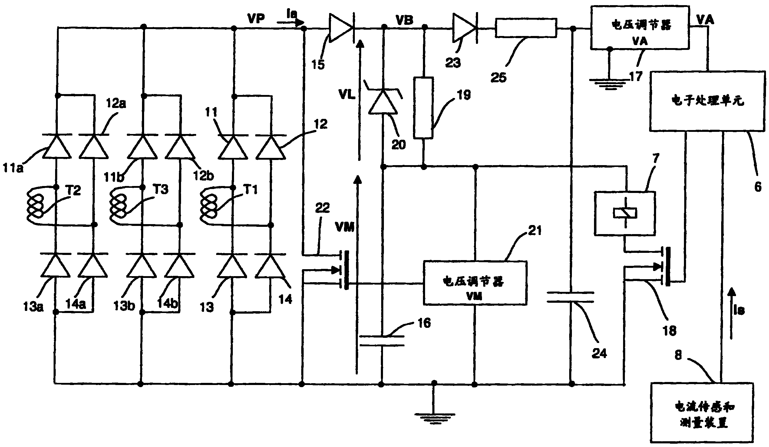
图3代表根据本发明实施例的断开装置的示意图;Figure 3 represents a schematic diagram of a disconnecting device according to an embodiment of the present invention;
图4在曲线31到33上例示了在断路器的瞬时加电阶段,根据图3的断开装置中的各种电压信号;和FIG. 4 illustrates on
图5代表根据本发明实施例的包含集成电路的断开装置的示意图。Fig. 5 represents a schematic diagram of a disconnect device including an integrated circuit according to an embodiment of the present invention.
优选实施例详述Detailed Description of Preferred Embodiments
表示在图1中的断路器作用在所述断路器的三根主导线1上。但是,应该注意到,本发明的器件可以包含任意数量的主导线。主导线与使流入这些导线的初级电流接通或断开的触头2连接。The circuit breaker shown in FIG. 1 acts on the three
与不同主导线相联系的电流传感器T1、T2、T3将大值的初级电流变换成与电子断开装置相适应的次级电流。整流电路3将电源电流Ia提供给断开装置的电源电路4。The current sensors T1 , T2 , T3 associated with the different main conductors transform the high-value primary current into a secondary current suitable for the electronic disconnection device. The
断路器包含设计成根据代表断路器的至少一根主导线中的初级电流强度的信号Is控制操作机构7的电子处理单元6。在表示在图1中的实施例中,代表初级电流强度的信号Is的提供由包含电流传感器的单独装置8完成。可以设想将相同电流传感器用于将电源电流Ia提供给电源电路4和将代表初级电流强度的信号Is的提供给电子处理单元。操作机构7使得能够通过作用断开触头2的机构9断开主导线1。The circuit breaker comprises an
以这种方式,电源电路4将电源电压提供给操作机构7。电源电路4装备有设计成将电源电压VA提供给电子处理单元6的电压调节器。In this way, the
在表示在图2中的根据现有技术的电子断开装置中,电流传感器T1的次级绕组与四个二极管11-14为一组形成的整流电桥连接。次级绕组的第一端与第一二极管11的阳极连接和与第二二极管13的阴极连接,而次级绕组的第二端与第三二极管12的阳极连接和与第四二极管14的阴极连接。第一和第三二极管11和12的阴极与正电源线VP连接。第二和第四二极管13和14的阳极与断开装置的电参考地连接。其它传感器T2和T3以相同的方式与分别用二极管11a、12a、13a和14a和11b、12b、13b和14b表示的两个整流电桥连接。二极管11a、11b、12a和12b的阴极与线VP连接。二极管13a、13b、14a和14b的阴极与断开装置的电参考地连接。In the electronic disconnection device according to the prior art shown in FIG. 2, the secondary winding of the current sensor T1 is connected to a rectifier bridge formed by a group of four diodes 11-14. The first end of the secondary winding is connected to the anode of the
电源电流Ia通过二极管15流入正电源线VP中,以便对存储电容器16充电。因此,存储电容器两端的电压VM使电源提供给操作机构。电源电流Ia还提供给设计成调节处理单元的电源电压VA的电压调节器17。The power supply current Ia flows into the positive power supply line VP through the
其它的传感和测量电流装置8使代表至少一个初级电流的信号Is提供给电子处理单元6。当初级电流超过断路器的断开阈值时,电子处理单元6将操作机构7的断开命令发送到控制晶体管18。然后,存储在存储电容器16中的能量用于提供操作机构。Further current sensing and measuring means 8 make a signal Is representative of at least one primary current available to the
通过测量电压VM和将控制命令提供给晶体管22的栅极,和通过电压调节器21调节设计成向操作机构提供电源的存储电容器两端的电压VM。二极管15使电源电流Ia流入对电容器16充电。电压VM一达到工作值,电压调节器21就发送使电源电流Ia反向的控制命令。当电压VM低于工作值时,电压调节器发送控制命令,使电源电流Ia的流动重新建立起来,以便重新对存储电容器16充电。By measuring voltage VM and supplying a control command to the gate of
表示在图3中的电子断开装置包含表示在图2中的和如上所述的组件。另外,图3的电子断开装置还包含设计成将升高电压VB提供给电压调节器17的升压装置,所述升压装置连接在二极管15的阴极和存储电容器16之间。在表示在图3中的情况中,升压装置包含电阻19和与所述电阻19并联反向安装的限压二极管20,以便当对存储电容器16充电时,升高电压VB迅速达到等于电容器两端的电压VM和所述二极管20的限制电压VL之和的值。存储电容器16一开始充电,电源电流Ia的至少一部分就流过电阻19。当电阻19两端的电压达到限制电压时,限压二极管20使这个电压保持在等于所述限制电压VL的值上。以这种方式,当开始对存储电容器16充电时,升高电压就迅速达到等于限制电压VL的值。The electronic disconnect device shown in Figure 3 contains the components shown in Figure 2 and described above. In addition, the electronic disconnection device of FIG. 3 also comprises boosting means designed to supply a boosted voltage VB to the
最好,限压二极管可以呈现这样的限制电压VL,其当存储电容器16一开始充电就使电子处理单元工作、大于或等于电子处理单元的电源电压VA的额定值。以这种方式,当对断路器加电时,以较短的延迟对电子处理单元16加电。Preferably, the voltage-limiting diode can exhibit a limiting voltage VL which enables the electronic processing unit to operate as soon as the
为操作机构的电源设计的存储电容器两端的电压VM通过电压调节器21调节。这个调节器使电阻19和二极管20中的电源电流Ia消耗的功率减少。The voltage VM across a storage capacitor designed for the power supply of the operating mechanism is regulated by a
当对断路器加电时,二极管23使次级电流流入对设计成对电压调节器17供电的电容器24充电。电容器24与电阻25结合在一起还对电压调节器17输入端上的升高电压VB进行滤波。When the circuit breaker is energized, the
在断路器的瞬时加电阶段,电压VM、VB和VA的值随时间的变化分别用图4的曲线31、32和33表示。During the momentary energization phase of the circuit breaker, the time variation of the values of the voltages VM, VB and VA is represented by the
到达时刻t1,电源电流Ia的一部分通过二极管15流过电阻19,对存储电容器16充电。电流Ia的另一部分流过二极管23和电阻25对电容器24充电。升高电压VB非常迅速地达到等于二极管20的限制电压VL的值,在这种情况下,限制电压VL大致等于电子处理单元的电源电压VA的额定值。因此,在时刻t1,升高电压VB具有大致等于电压VA的额定值的值。因此,充分地对电压调节器17供电,传递等于电压VA的额定值的电压。When time t1 is reached, part of the power supply current Ia flows through the
应该注意到,在时刻t1,存储电容器16两端的电压VM的值显著地低于电压VA的额定值。与其中存储电容器两端的电压VM直接对电压调节器17供电的现有技术的断开装置相比,这个电压VM的值仍然不足以使电压调节器17传递电子处理单元的额定电源电压。It should be noted that at instant t1 the value of the voltage VM across the
在时刻t1和t3之间,电源电流Ia用于对存储电容器16充电。升高电压VB大致等于存储电容器16两端的电压VM和二极管20的限制电压VL之和。Between times t1 and t3 the supply current Ia is used to charge the
应该注意到,在时刻t2,存储电容器两端的电压VM等于电压VA的额定值。与其中存储电容器两端的电压VM对电压调节器17供电的现有技术的断开装置相比,只有在这个时刻t2这个电压VM才足以使电压调节器17提供等于电压VA的额定值的电压。因此,在这个实施例中,本发明的断开装置使电子处理单元的加电提前。与其中存储电容器两端的电压VM对电压调节器17供电的现有技术的断开装置相比的时间增加(gain)是t2-t1。It should be noted that at instant t2 the voltage VM across the storage capacitor is equal to the nominal value of the voltage VA. In contrast to prior art disconnecting devices in which the voltage VM across the storage capacitor powers the
在时刻t3,电压VM达到工作值VMc和电压调节器21将控制命令发送到晶体管22使次级电流转向。对于这个部分,升高电压VB达到大致与工作值VMc和限制值VL之和相对应的最大值VB+。在时刻t3和t4之间,电压VM和VB因存储电容器16放电而下降。在时刻t4,电压VM达到低于工作值VMc的值和电压调节器21将控制命令发送到晶体管22使次级电流反向重新对存储电容器16充电。在时刻t5,电压VM的调节重复由时刻t3和t5之间的时间组成的循环。At instant t3, voltage VM reaches operating value VMc and
图5的电子断开装置包含集成电路51,除了别的部件之外,集成电路51包含电压调节器17、电子处理单元6和电压调节器21。该集成电路包含与该与电参考地连接的电容器52连接的电压调节器17的输出端。The electronic disconnect device of FIG. 5 comprises an
在上述的实施例中,升压装置可以包含与存储电容器串联的电阻19和/或电压限制器20。在其它的实施例中,升压装置可以包含像半导体电路或集成电路那样使电压升高的其它电子电路。In the embodiments described above, the boost means may comprise a
根据本发明的断开装置的一个优点是,当对断路器加电时,保证尽可能早地对电子处理单元加电。One advantage of the disconnecting device according to the invention is that, when energizing the circuit breaker, it is ensured that the electronic processing unit is energized as early as possible.
Claims (9)
Applications Claiming Priority (2)
| Application Number | Priority Date | Filing Date | Title |
|---|---|---|---|
| FR0508273 | 2005-08-02 | ||
| FR0508273A FR2889631B1 (en) | 2005-08-02 | 2005-08-02 | ELECTRONIC TRIGGER WITH A POWER CIRCUIT COMPRISING VOLTAGE ENHANCER MEANS AND CIRCUIT BREAKER COMPRISING SUCH A TRIGGER |
Publications (2)
| Publication Number | Publication Date |
|---|---|
| CN1909314A true CN1909314A (en) | 2007-02-07 |
| CN1909314B CN1909314B (en) | 2010-05-12 |
Family
ID=36143698
Family Applications (1)
| Application Number | Title | Priority Date | Filing Date |
|---|---|---|---|
| CN200610108217XA Active CN1909314B (en) | 2005-08-02 | 2006-08-01 | Equipped with electronic disconnecting devices for power circuits and circuit breakers incorporating disconnecting devices |
Country Status (9)
| Country | Link |
|---|---|
| US (1) | US7656636B2 (en) |
| EP (1) | EP1750343B1 (en) |
| JP (1) | JP5014699B2 (en) |
| CN (1) | CN1909314B (en) |
| BR (1) | BRPI0603095B1 (en) |
| ES (1) | ES2558017T3 (en) |
| FR (1) | FR2889631B1 (en) |
| PL (1) | PL1750343T3 (en) |
| RU (1) | RU2383960C2 (en) |
Cited By (2)
| Publication number | Priority date | Publication date | Assignee | Title |
|---|---|---|---|---|
| CN103314496A (en) * | 2010-10-15 | 2013-09-18 | Bsh博世和西门子家用电器有限公司 | Circuit assembly for operating an electric load, control device for controlling a drive motor of a household appliance, household appliance and method for operating an electric load in a household appliance |
| CN104620455A (en) * | 2012-08-01 | 2015-05-13 | Abb技术股份公司 | A power supply and measuring device for an intelligent electronic device |
Families Citing this family (10)
| Publication number | Priority date | Publication date | Assignee | Title |
|---|---|---|---|---|
| DE202008002736U1 (en) * | 2008-02-27 | 2009-07-09 | Weidmüller Interface GmbH & Co. KG | monitoring device |
| JP5535323B2 (en) * | 2009-09-29 | 2014-07-02 | 湖北盛佳▲電▼器▲設備▼有限公司 | Built-in intelligent circuit breaker and micro circuit breaker with automatic switching-in function |
| JP5514318B2 (en) * | 2009-09-29 | 2014-06-04 | 湖北盛佳▲電▼器▲設備▼有限公司 | Intelligent circuit breaker with automatic switching-in function |
| FR2956212B1 (en) * | 2010-02-08 | 2012-03-09 | Schneider Electric Ind Sas | DEVICE AND METHOD FOR ELECTRIC POWER COUNTING |
| RU2481665C1 (en) * | 2011-08-19 | 2013-05-10 | Владимир Иванович Винокуров | Method for electronic disconnection of automatic circuit breaker and electronic automatic circuit breaker |
| DE102011083680B4 (en) * | 2011-09-29 | 2022-05-05 | Siemens Aktiengesellschaft | Circuit breaker, circuit arrangement and method for regulating a voltage in a circuit breaker |
| JP6839813B2 (en) * | 2016-12-20 | 2021-03-10 | パナソニックIpマネジメント株式会社 | Electric circuit abnormality detection device and switch equipped with it |
| DE102017202536B4 (en) * | 2017-02-16 | 2018-10-04 | Continental Automotive Gmbh | Device for protecting loads from overvoltage |
| DE202019100449U1 (en) | 2019-01-25 | 2020-04-30 | Wago Verwaltungsgesellschaft Mbh | Bracket device, control cabinet and readout device |
| DE102020123260A1 (en) * | 2020-09-07 | 2022-03-10 | Westnetz Gmbh | busbar support |
Family Cites Families (13)
| Publication number | Priority date | Publication date | Assignee | Title |
|---|---|---|---|---|
| JPS62171409A (en) * | 1986-01-24 | 1987-07-28 | 株式会社東芝 | Automatic monitor of equipment of generating station and substation |
| JP2659639B2 (en) * | 1991-11-11 | 1997-09-30 | 松下電工株式会社 | Power supply for protective relay |
| FR2705506B1 (en) * | 1993-05-21 | 1995-07-07 | Merlin Gerin | Electronic trip device comprising a power control device. |
| US5937622A (en) * | 1995-07-26 | 1999-08-17 | Black & Decker Inc. | Cordless electric lawn mower having energy management control system |
| JPH10126952A (en) * | 1996-10-24 | 1998-05-15 | Fuji Electric Co Ltd | Circuit breaker |
| RU5689U1 (en) * | 1997-01-28 | 1997-12-16 | Бойкевич Анатолий Михайлович | ELECTRONIC SWITCH POWER SUPPLY UNIT |
| DE19738699A1 (en) * | 1997-08-29 | 1999-03-04 | Siemens Ag | Circuit breaker release magnet operating circuit |
| DE19819149A1 (en) * | 1998-04-24 | 1999-10-28 | Siemens Ag | Circuit breaker with current supply for electronic overcurrent release |
| RU2160478C2 (en) * | 1998-12-03 | 2000-12-10 | Кузнецов Владимир Владимирович | Dynamically disconnected single-phase ac circuit breaker |
| DE19954038A1 (en) * | 1999-10-29 | 2001-05-03 | Siemens Ag | Low-voltage (LV) circuit-breaker release |
| DE10010924A1 (en) * | 2000-03-06 | 2001-09-13 | Abb Research Ltd | DC supply device using AC current source, e.g. for protective switch trip circuit, has rectifier arrangement with associated electronic switch and storage capacitor |
| FR2826197B1 (en) * | 2001-06-19 | 2003-08-15 | Schneider Electric Ind Sa | ELECTRONIC TRIGGER COMPRISING A POWER CAPACITOR FOR A TRIGGERING COIL |
| JP2005093303A (en) * | 2003-09-19 | 2005-04-07 | Meidensha Corp | Power supply device for solenoid operated type circuit breaker |
-
2005
- 2005-08-02 FR FR0508273A patent/FR2889631B1/en not_active Expired - Fee Related
-
2006
- 2006-06-27 EP EP06354020.7A patent/EP1750343B1/en active Active
- 2006-06-27 PL PL06354020T patent/PL1750343T3/en unknown
- 2006-06-27 ES ES06354020.7T patent/ES2558017T3/en active Active
- 2006-07-24 US US11/491,235 patent/US7656636B2/en active Active
- 2006-07-27 JP JP2006205180A patent/JP5014699B2/en active Active
- 2006-08-01 RU RU2006128031/09A patent/RU2383960C2/en active
- 2006-08-01 CN CN200610108217XA patent/CN1909314B/en active Active
- 2006-08-01 BR BRPI0603095-5A patent/BRPI0603095B1/en active IP Right Grant
Cited By (4)
| Publication number | Priority date | Publication date | Assignee | Title |
|---|---|---|---|---|
| CN103314496A (en) * | 2010-10-15 | 2013-09-18 | Bsh博世和西门子家用电器有限公司 | Circuit assembly for operating an electric load, control device for controlling a drive motor of a household appliance, household appliance and method for operating an electric load in a household appliance |
| CN103314496B (en) * | 2010-10-15 | 2016-03-09 | Bsh家用电器有限公司 | For run electric loading circuit arrangement, for triggering the control device of the drive motor of home appliances, home appliances and the method for running the electric loading in home appliances |
| CN104620455A (en) * | 2012-08-01 | 2015-05-13 | Abb技术股份公司 | A power supply and measuring device for an intelligent electronic device |
| CN104620455B (en) * | 2012-08-01 | 2017-07-28 | Abb技术股份公司 | Power supply and measuring apparatus for intelligent electronic device |
Also Published As
| Publication number | Publication date |
|---|---|
| JP5014699B2 (en) | 2012-08-29 |
| PL1750343T3 (en) | 2016-04-29 |
| FR2889631B1 (en) | 2007-09-14 |
| BRPI0603095A (en) | 2007-03-20 |
| BRPI0603095B1 (en) | 2017-11-21 |
| EP1750343B1 (en) | 2015-11-04 |
| ES2558017T3 (en) | 2016-02-01 |
| US7656636B2 (en) | 2010-02-02 |
| US20070030616A1 (en) | 2007-02-08 |
| CN1909314B (en) | 2010-05-12 |
| RU2006128031A (en) | 2008-02-10 |
| FR2889631A1 (en) | 2007-02-09 |
| RU2383960C2 (en) | 2010-03-10 |
| JP2007042638A (en) | 2007-02-15 |
| EP1750343A1 (en) | 2007-02-07 |
Similar Documents
| Publication | Publication Date | Title |
|---|---|---|
| CN109168326B (en) | power supply unit | |
| CN2867690Y (en) | Power-supply management system | |
| US9024609B2 (en) | Circuit and method for providing hold-up time in a DC-DC converter | |
| WO2012140840A1 (en) | Converter device and semiconductor device | |
| US20220089111A1 (en) | Vehicle power control apparatus and vehicle power apparatus | |
| CN101048929A (en) | Ultra low power stand-by supply | |
| JP7272897B2 (en) | Charge/discharge control device and battery and DC power supply system equipped with the same | |
| CN1909314B (en) | Equipped with electronic disconnecting devices for power circuits and circuit breakers incorporating disconnecting devices | |
| KR20170100616A (en) | Circuit devices for operating semiconductor light sources | |
| CN1457140A (en) | Over current output protective circuit and switching constant voltage power supply | |
| CN109716867B (en) | Protection circuit of dimming device and dimming device | |
| CN1883025A (en) | Drive circuit of DC voltage driven magnet contactor and power converter | |
| JP2014030317A (en) | Reverse-connection protection circuit and electronic equipment having the same | |
| US8619439B2 (en) | Flyback boost circuit with current supplied to secondary side of transformer circuit prior to boost operation and strobe device using the same | |
| JP2007318891A (en) | Power circuit for driving switching element | |
| TW201720233A (en) | Dimming device | |
| CN107370369B (en) | Boost chopper circuit | |
| SE507368C2 (en) | Snubber circuit, voltage converter circuit and method in such a snubber circuit | |
| JP4293197B2 (en) | DC power supply holding circuit | |
| CN113471942B (en) | Power supply device with protection circuit | |
| CN102160273A (en) | Boost converter and method for operating electrical load on boost converter | |
| JP2018113735A (en) | Power supply device and illuminating device comprising the same | |
| US20190342959A1 (en) | Light emitting element driving device and driving method thereof | |
| JP6054236B2 (en) | Power supply circuit, semiconductor integrated circuit, isolated switching power supply | |
| CN100386940C (en) | Power Systems |
Legal Events
| Date | Code | Title | Description |
|---|---|---|---|
| C06 | Publication | ||
| PB01 | Publication | ||
| C10 | Entry into substantive examination | ||
| SE01 | Entry into force of request for substantive examination | ||
| C14 | Grant of patent or utility model | ||
| GR01 | Patent grant |