CN1920962A - Magnetic recording medium and method of manufacturing the same - Google Patents
Magnetic recording medium and method of manufacturing the same Download PDFInfo
- Publication number
- CN1920962A CN1920962A CNA2006101160003A CN200610116000A CN1920962A CN 1920962 A CN1920962 A CN 1920962A CN A2006101160003 A CNA2006101160003 A CN A2006101160003A CN 200610116000 A CN200610116000 A CN 200610116000A CN 1920962 A CN1920962 A CN 1920962A
- Authority
- CN
- China
- Prior art keywords
- magnetic recording
- recording medium
- magnetic
- lubricant
- processing
- Prior art date
- Legal status (The legal status is an assumption and is not a legal conclusion. Google has not performed a legal analysis and makes no representation as to the accuracy of the status listed.)
- Granted
Links
Images


Classifications
-
- G—PHYSICS
- G11—INFORMATION STORAGE
- G11B—INFORMATION STORAGE BASED ON RELATIVE MOVEMENT BETWEEN RECORD CARRIER AND TRANSDUCER
- G11B5/00—Recording by magnetisation or demagnetisation of a record carrier; Reproducing by magnetic means; Record carriers therefor
- G11B5/84—Processes or apparatus specially adapted for manufacturing record carriers
- G11B5/8408—Processes or apparatus specially adapted for manufacturing record carriers protecting the magnetic layer
-
- G—PHYSICS
- G11—INFORMATION STORAGE
- G11B—INFORMATION STORAGE BASED ON RELATIVE MOVEMENT BETWEEN RECORD CARRIER AND TRANSDUCER
- G11B5/00—Recording by magnetisation or demagnetisation of a record carrier; Reproducing by magnetic means; Record carriers therefor
- G11B5/62—Record carriers characterised by the selection of the material
- G11B5/73—Base layers, i.e. all non-magnetic layers lying under a lowermost magnetic recording layer, e.g. including any non-magnetic layer in between a first magnetic recording layer and either an underlying substrate or a soft magnetic underlayer
- G11B5/739—Magnetic recording media substrates
Landscapes
- Manufacturing Of Magnetic Record Carriers (AREA)
- Magnetic Record Carriers (AREA)
Abstract
本发明提供一种使磁记录介质外周部的润滑层膜厚均匀化、使磁头上浮稳定化的方法。该方法用于制造具有润滑层的磁记录介质,其特征在于,在保护层上涂布液体润滑剂后,一边使磁记录介质(20)旋转,一边利用带按压器件(16),将含有溶剂的加工带(11)同时按压在所述磁记录介质的端面和数据面的外周部,擦去所述液体润滑剂。非磁性基板的厚度优选为0.635mm以下。另外,涂布液体润滑剂后,进一步施加加热处理,再利用加工带进行擦去。
The present invention provides a method for uniformizing the film thickness of a lubricating layer on the outer peripheral portion of a magnetic recording medium and stabilizing the floating of a magnetic head. The method is used to manufacture a magnetic recording medium with a lubricating layer. It is characterized in that, after coating a liquid lubricant on the protective layer, the magnetic recording medium (20) is rotated while using a belt to press the device (16), and the solvent-containing The processing belt (11) simultaneously presses the end surface of the magnetic recording medium and the outer periphery of the data surface to wipe off the liquid lubricant. The thickness of the non-magnetic substrate is preferably 0.635 mm or less. In addition, after the liquid lubricant is applied, heat treatment is further applied, and then wiped off with a processing tape.
Description
技术领域technical field
本发明涉及搭载在作为信息处理装置的外部存储装置而使用的固定磁盘装置等上的磁盘等磁记录介质及其制造方法,更详细地涉及改善磁记录介质的表面形状,使磁头低上浮化成为可能的磁记录介质及其制造方法。The present invention relates to a magnetic recording medium such as a magnetic disk mounted on a fixed magnetic disk device or the like used as an external storage device of an information processing device, and a method for manufacturing the same. Possible magnetic recording media and methods for their manufacture.
背景技术Background technique
作为计算机等信息处理装置和外部存储装置,大多使用固定磁盘装置,近年来,作为便携电话和MP3播放器等小型存储装置也开始利用固定磁盘装置。Fixed magnetic disk devices are often used as information processing devices such as computers and external storage devices, and in recent years, fixed magnetic disk devices have also begun to be used as small storage devices such as mobile phones and MP3 players.
搭载在该固定磁盘装置上的磁记录介质是用于磁记录信息的部件,一般在基板上层叠底层、磁记录层、保护层,再涂布液体润滑层。基板使用盘状的非磁性材料、例如铝合金和玻璃,也有在表面上用无电解镀法等形成由Ni-P膜构成的非磁性金属膜。在非磁性基板上实施构造(texture)加工,用溅射法等在其上形成用于使磁特性提高的由Cr等构成的非磁性金属底层,再用溅射法等形成记录信息的由Co合金等构成的磁记录层。为了保护磁记录层,再用溅射法或等离子体CVD法形成润滑性优异、难以磨耗的称之为金刚石类碳(DLC)的硬的无定形碳保护膜,在其上涂布液体润滑剂。作为液体润滑层的涂布法,考虑生产性和装置简便的方面,大多使用浸渍涂布法(浸渍法)。这是根据所希望的膜厚,用氟碳类溶剂将液体润滑剂原液稀释为适当浓度,在所得到的涂布液中,使基板浸渍一定的时间后,以一定的速度引起基板或引下涂布液、使溶剂蒸发,并使残存在基板上的润滑剂成分吸附在保护膜上的方法。作为其它的涂布方法,也可以使用旋转涂、喷涂法、蒸镀法。在保护层上被涂布的液体润滑剂,主要可以使用全氟聚醚(PFPE)。The magnetic recording medium mounted on this fixed magnetic disk unit is used for magnetically recording information, and generally a base layer, a magnetic recording layer, and a protective layer are laminated on a substrate, and a liquid lubricating layer is then applied. A disk-shaped non-magnetic material such as aluminum alloy and glass is used as the substrate, and a non-magnetic metal film composed of Ni-P film may be formed on the surface by electroless plating or the like. Implement texture processing on the non-magnetic substrate, form a non-magnetic metal underlayer composed of Cr, etc. for improving magnetic properties by sputtering, etc., and then form a layer of Co that records information by sputtering, etc. A magnetic recording layer composed of an alloy or the like. In order to protect the magnetic recording layer, a hard amorphous carbon protective film called diamond-like carbon (DLC) with excellent lubricity and difficult to wear is formed by sputtering or plasma CVD, and a liquid lubricant is coated on it. . As a coating method for the liquid lubricating layer, a dip coating method (dipping method) is often used in consideration of productivity and ease of installation. According to the desired film thickness, the liquid lubricant stock solution is diluted to an appropriate concentration with a fluorocarbon solvent, and the substrate is immersed in the obtained coating solution for a certain period of time, and the substrate is caused or drawn down at a certain speed. A method of coating liquid, evaporating the solvent, and adsorbing the lubricant component remaining on the substrate to the protective film. As other coating methods, spin coating, spray coating, and vapor deposition can also be used. As the liquid lubricant to be coated on the protective layer, mainly perfluoropolyether (PFPE) can be used.
近年来,随着计算机信息处理的高速化,存在要求更加增大磁记录介质记录容量的状况。磁记录介质的记录容量,因为可以由缩小磁头的上浮量(即磁头和磁记录介质表面之间的距离)而增大,所以,磁头上浮量变得越来越小,最近,要求在0.4μin以下的稳定飞行。磁头的上浮量降低时,磁头和磁记录介质的接触机会增多,但伴之而来的因为润滑剂变得容易移向磁头,所以,磁头的上浮变得不稳定,使记录再生特性和磁头寻找耐久性变得恶化的坏影响变得显著。In recent years, along with the increase in the speed of computer information processing, there is a situation in which the recording capacity of magnetic recording media is required to be further increased. The recording capacity of the magnetic recording medium can be increased by reducing the floating amount of the magnetic head (that is, the distance between the magnetic head and the surface of the magnetic recording medium), so the floating amount of the magnetic head becomes smaller and smaller. Recently, it is required to be below 0.4μin stable flight. When the floating amount of the magnetic head is reduced, the chance of contact between the magnetic head and the magnetic recording medium increases, but the accompanying lubricant becomes easy to move to the magnetic head, so the floating of the magnetic head becomes unstable, and the recording and reproduction characteristics and the magnetic head seek The bad influence that the durability deteriorates becomes remarkable.
专利文献1:日本专利特开2003-6849号公报Patent Document 1: Japanese Patent Laid-Open No. 2003-6849
专利文献2:日本专利特公平7-58545号公报Patent Document 2: Japanese Patent Application Publication No. 7-58545
专利文献3:日本专利特开2004-326880号公报Patent Document 3: Japanese Patent Laid-Open No. 2004-326880
以往以来认识到涂布润滑层时,润滑剂不一定被均匀地涂布、产生膜厚的分布,为了解决该问题,至今提出在涂覆有润滑剂的表面上通过按压擦拭器(wiper)和抛光轮(buff),由此将润滑剂的分布均匀化,使表面平坦化的方案(例如参照专利文献1、专利文献2)。这些方法中,实施摩擦接触处理和抛光处理的部分都是以磁记录介质的数据面内(即磁头上浮区域、记录区域)为对象。但是,判明:随着磁头上浮量减少,以往不被关注的在磁头上浮区域以外的局部润滑剂的异常涂布对磁头上浮特性带来坏影响。图9是用于说明在浸渍涂布法中产生的问题的模式图,为了容易理解进行夸大地描写。因为浸渍涂布法利用重力使涂布液在涂布表面上流下,所以,如图9(a)所示,在磁记录介质20的下侧外周部形成涂布液滞留21,溶剂蒸发后,如图9(b)所示地在磁记录介质外周的端面上产生残存润滑剂22。判明:磁记录介质端面是磁头上浮区域外,不是与磁头直接相对,但残存的润滑剂随着时间的经过、在磁记录介质表面上扩散,对磁头的上浮带来坏影响。润滑剂向端面的残存不限于浸渍涂布法。在旋转涂布法中,涂布时的离心力和重力同样地发挥作用,产生类似的现象。It has been recognized in the past that when coating a lubricating layer, the lubricant is not necessarily uniformly coated and the film thickness distribution occurs. In order to solve this problem, it has been proposed to press the wiper (wiper) and A polishing wheel (buff), thereby uniformizing the distribution of the lubricant and flattening the surface (for example, refer to Patent Document 1 and Patent Document 2). In these methods, the parts where the rubbing treatment and the polishing treatment are performed are all targeted at the data surface of the magnetic recording medium (that is, the magnetic head floating area and the recording area). However, it has been found that, as the head float amount decreases, the abnormal coating of the lubricant outside the head float region, which has not been paid much attention in the past, has a bad influence on the head float characteristics. FIG. 9 is a schematic diagram for explaining problems occurring in the dip coating method, and is exaggerated for easy understanding. Because the dipping coating method utilizes gravity to make the coating liquid flow down on the coating surface, so, as shown in FIG. As shown in FIG. 9( b ),
为了解决该现象,提出在端面按压摩擦接触带、除去润滑剂的方法(例如参照专利文献3)。但是,发明人等研讨的结果发现,在只在端面按压摩擦接触带的方法中,随着被用于磁记录介质的基板变薄,就会产生新的问题。即,在磁记录介质端面流下的润滑剂涂布液的量,大致被磁记录介质的表面积左右而不依存于板厚。但是,因为随着磁记录介质的板厚变薄,磁记录介质端面面积按照板厚减少的程度相应地减少,所以,端面单位面积上流下的涂布液量增大。其结果,如果是以往,在端面残存的润滑剂就变得在磁记录介质端面近处的磁记录介质表面也残存。在基板、特别是薄的磁记录介质中,从润滑剂刚涂布后,在数据面侧的外周部润滑剂滞留被确认。在该润滑剂的滞留处,磁头接触时,引起润滑剂向磁头移动,磁头的上浮变得不稳定,对记录再生特性和磁头寻找耐久性带来坏影响。In order to solve this phenomenon, a method of pressing the frictional contact belt on the end surface to remove the lubricant has been proposed (for example, refer to Patent Document 3). However, as a result of studies by the inventors, it has been found that in the method of pressing the frictional contact tape only on the end surface, new problems arise as the thickness of the substrate used for the magnetic recording medium becomes thinner. That is, the amount of the lubricant coating liquid flowing down the end surface of the magnetic recording medium is largely determined by the surface area of the magnetic recording medium and does not depend on the plate thickness. However, as the thickness of the magnetic recording medium becomes thinner, the area of the end surface of the magnetic recording medium decreases in proportion to the decrease in the thickness of the magnetic recording medium, so the amount of coating liquid flowing down per unit area of the end surface increases. As a result, conventionally, the lubricant remaining on the end face also remains on the surface of the magnetic recording medium in the vicinity of the end face of the magnetic recording medium. In a substrate, especially a thin magnetic recording medium, it has been confirmed that the lubricant stays in the outer peripheral portion on the data surface side immediately after the lubricant is applied. When the magnetic head is brought into contact with the stagnant place of the lubricant, the lubricant moves to the magnetic head, and the floating of the magnetic head becomes unstable, which adversely affects the recording and reproduction characteristics and the seek durability of the magnetic head.
发明内容Contents of the invention
本发明鉴于上述问题,提供一种磁记录介质的制造方法,用于制造具有非磁性基板、磁记录层、保护层和润滑层的磁记录介质,其特征在于,在该保护层上涂布液体润滑剂后,一边使上述磁记录介质旋转,一边将含有溶剂的加工带同时按压在上述磁记录介质的端面和数据面的外周部,擦去上述液体润滑剂。In view of the above problems, the present invention provides a method for manufacturing a magnetic recording medium, which is used to manufacture a magnetic recording medium having a non-magnetic substrate, a magnetic recording layer, a protective layer and a lubricating layer, wherein the protective layer is coated with a liquid After applying the lubricant, while rotating the magnetic recording medium, simultaneously press a processing tape containing a solvent against the end surface of the magnetic recording medium and the outer periphery of the data surface to wipe off the liquid lubricant.
上述非磁性基板的厚度优选为0.635mm以下。The thickness of the non-magnetic substrate is preferably 0.635 mm or less.
另外,优选在涂布上述液体润滑剂后,进一步实施加热处理,然后再利用上述加工带进行擦去。In addition, it is preferable to further perform heat treatment after applying the above-mentioned liquid lubricant, and then wipe off with the above-mentioned processing tape.
另外,上述加工带的负荷优选为15g以上40g以下。Moreover, it is preferable that the load of the said processing belt is 15 g or more and 40 g or less.
另外,优选在擦去上述液体润滑剂后,在对上述加工带维持按压力的状态下,从上述磁记录介质拉出该加工带。In addition, it is preferable to pull out the processing tape from the magnetic recording medium while maintaining the pressing force on the processing tape after wiping off the liquid lubricant.
另外,本发明的磁记录介质,其特征在于,利用上述任一种制造方法制造。In addition, the magnetic recording medium of the present invention is characterized in that it is produced by any one of the above-mentioned production methods.
根据本发明,就可以有效地减少磁记录介质端面的润滑剂和磁记录介质数据面的最外周部的润滑剂滞留,抑制润滑剂向磁头的移动,另外,即使是低上浮的磁头,也可以形成能够稳定飞行的磁盘表面。According to the present invention, the lubricant on the end face of the magnetic recording medium and the lubricant on the outermost peripheral portion of the data surface of the magnetic recording medium can be effectively reduced, and the movement of the lubricant to the magnetic head can be suppressed. Form a disk surface capable of stable flight.
附图说明:Description of drawings:
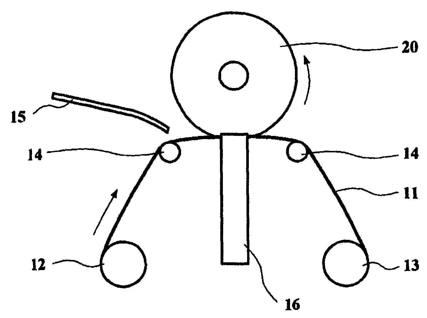
图1是表示本发明的磁记录介质外周部的擦去加工方法的一个例子的模式图。FIG. 1 is a schematic view showing an example of a method of erasing the outer peripheral portion of a magnetic recording medium according to the present invention.
图2是表示本发明的带按压器件的构成例子和按压方法的例子的模式图。Fig. 2 is a schematic view showing a configuration example of a belt pressing device and an example of a pressing method according to the present invention.
图3是表示本发明的导向辊构成例子的模式图。Fig. 3 is a schematic view showing a configuration example of a guide roller of the present invention.
图4是表示本发明的对照例2的擦去加工方法的模式图。Fig. 4 is a schematic diagram showing a method of wiping off in Comparative Example 2 of the present invention.
图5是表示本发明的磁记录介质的构成例子的截面模式图。FIG. 5 is a schematic cross-sectional view showing a configuration example of the magnetic recording medium of the present invention.
图6是用于说明本发明的磁记录介质外周部的截面模式图。Fig. 6 is a schematic cross-sectional view illustrating the outer periphery of the magnetic recording medium of the present invention.
图7是表示实施例1和对照例1的磁记录介质外周部的膜厚分布的曲线图。FIG. 7 is a graph showing the film thickness distribution in the peripheral portion of the magnetic recording medium of Example 1 and Comparative Example 1. FIG.
图8是表示实施例1和对照例2的磁记录介质外周部的膜厚分布的曲线图。8 is a graph showing the film thickness distribution of the outer periphery of the magnetic recording medium of Example 1 and Comparative Example 2. FIG.
图9是用于说明磁记录介质的润滑剂滞留的模式图。FIG. 9 is a schematic diagram for explaining lubricant retention in a magnetic recording medium.
符号说明Symbol Description
11...加工带11...Processing belt
12...带的供给卷盘12...with supply reel
13...带的卷取卷盘13...with take-up reel
14...导向辊14...Guide roller
15...溶剂供给喷嘴15...solvent supply nozzle
16...带按压器件16...with pressing device
17...衬垫17...Padding
18...衬垫保持器件18...pad retention device
20...磁记录介质20...Magnetic recording media
21...涂布液滞留21... Coating solution retention
22...残存润滑剂22...residual lubricant
25...磁记录介质的端面25...The end face of the magnetic recording medium
26...磁记录介质的数据面26...The data side of the magnetic recording medium
31...非磁性基板31...Non-magnetic substrate
32...底层32...bottom
33...磁记录层33...Magnetic recording layer
34...保护层34...protective layer
35...润滑层35...lubricating layer
具体实施方式Detailed ways
以下,参照图面,详细说明本发明的实施方式。Hereinafter, embodiments of the present invention will be described in detail with reference to the drawings.
图1是用于说明本发明的一个实施方式的图,是擦去加工形成有润滑层的磁记录介质20的端面和数据面的外周部的机构模式图。图6是放大表示磁记录介质20的端部的模式图,端面25和数据面26的外周部是作为加工对象的加工区域。FIG. 1 is a diagram for explaining one embodiment of the present invention, and is a schematic diagram of a mechanism for wiping off an end surface of a
一边使涂布有液体润滑层的磁记录介质20在箭头方向以1000~3000rpm旋转,一边由带按压器件16将含有溶剂的加工带11按压在磁记录介质上。加工带11从带供给卷盘12供给,在加工带附近所图示的箭头方向上送出。润滑剂的溶剂从溶剂供给喷嘴15进行供给,加工带11含有溶剂后,被按压在磁记录介质,进行擦去加工。加工后,被容纳在带卷取卷盘13中。作为加工带,优选尼龙聚酯的织布。这是因为使用的溶剂有含浸性、但不溶解,微粒等的污染少。另外,作为使用的溶剂,如果具有溶解润滑剂的作用就不特别要求其种类,但优选异丙醇或全氟碳。这些对润滑剂有适当的溶解性。另外,来自溶剂供给喷嘴15的溶剂滴加量优选是0.01~0.10ml/分钟。While rotating the
图2是放大表示带按压器件16和磁记录介质20的接触部的模式图,图2a表示安装磁记录介质后、进行擦去加工前的状态,图2b表示加工中的状态,图2c表示加工后的状态。带按压器件16由衬垫17和衬垫保持器件18构成,衬垫保持器件18在夹持磁记录介质的方向上能够开闭。图中的箭头表示衬垫保持器件18的移动方向。Fig. 2 is an enlarged schematic view showing the contact portion of the
图2a是将带按压器件16刚按压在磁记录介质的状态,但衬垫保持器件18成为开的状态。这里,所谓开的状态,指的是在磁记录介质方向上移动带按压器件16时,在衬垫17和其之间夹着的加工带11被设定成不接触磁记录介质的数据面的间隙。加工带11优选保持为如图所图示的圆弧状(或山形)。图3是用于说明将加工带保持为圆弧状的方法的例子的图,作为导向辊14、使用中央凸的桶状的辊,在2个导向辊14之间,由赋予加工带适当的张力,可以保持圆弧状的形状。由这样制作,在加工时,可以成为带端不接触磁记录介质的表面,可以抑制意想不到的加工伤和微粒的发生。FIG. 2 a shows the state immediately after the
在加工时使衬垫保持器件18成为闭的状态,由衬垫17将含有溶剂的湿加工带11以所希望的面积压力按压在磁记录介质上。此时,如图2b所示地,加工带11为コ字型,进行磁记录介质的端面25和数据面26的外周部的处理。在个别处理数据面和端面的方法中,增加加工时间。通过同时加工,从加工装置数量、带使用量方面出发也有利于减少成本。衬垫17优选以磁记录介质垂直方向的负荷为15~40g进行按压。这是因为负荷过低时没有擦去效果,负荷过高时带和磁记录介质之间的摩擦力变高,就从带上产生灰尘。During processing, the
擦去加工结束后,以衬垫保持器件18成为闭的状态,即对加工带施加按压力,以带成为コ字型的状态,如图2c那样地从磁记录介质拉出带按压器件16。这是为了避免擦去的润滑剂残留在磁记录介质上。After the wiping process is completed, the
本发明的磁记录介质的构成、以及各层材料和成膜条件等没有特别限定。除了通过先前所示的确定工序进行液体润滑层的处理以外,可以适用本技术领域中的常用技术。The configuration of the magnetic recording medium of the present invention, the material of each layer, film formation conditions, and the like are not particularly limited. In addition to performing the treatment of the liquid lubricating layer through the defined procedures shown previously, common techniques in this technical field can be applied.
图5是表示磁记录介质构成的一个例子的截面模式图,在非磁性基板31上形成底层32,在其上以溅射方式和CVD方式等顺序形成磁记录层33、保护层34后,例如以浸渍涂布法涂布润滑层35。也可以根据需要设置取向控制层、中间层、软磁性里层等附加层。5 is a schematic cross-sectional view showing an example of the structure of a magnetic recording medium. A
非磁性基板31可以是由铝合金、化学强化玻璃、结晶化玻璃、陶瓷、硅、聚碳酸酯、高分子树脂等材料制成的基板,也可以是没有特别限定的基板。其大小没有特别限定,但适用直径为0.85英寸~2.5英寸、厚度为0.635mm以下的磁记录介质时可以得到特别的效果。The
底层32可以由常用的任意成分形成,没有特别限定。例如可以使用Cr、Cr-W、Cr-V、Cr-Mo、Cr-Si、Ni-Al、Co-Cr、Mo、W、Pt等。膜厚优选为20nm以下,特别优选为10~20nm。The
磁记录层33可以使用常用的磁性材料,例如可以使用以CoCrTaPt、CoCrTaPt-Cr2O3、CoCrTaPt-SiO2、CoCrTaPt-ZrO2、CoCrTaPt-TiO2、CoCrTaPt-Al2O3等成分制成的磁记录层。膜厚优选为20nm以下,特别优选为10~20nm。也可以使用多层磁记录层作为多层结构的记录层。
从磁头冲击、外界腐蚀物质等的腐蚀观点出发,保护层34具有保护磁记录层的功能,例如可以使用无定形碳、金刚石类碳和加氮无定形碳等。保护层的厚度优选为5.0nm以下,特别优选为2.0~4.0nm。The
形成润滑层35的润滑剂优选全氟聚醚,例如可以使用Z-dol、Z-tetraol、Z-dolTX、AM类、膦腈(phosphazene)类等。根据所希望的,可以是混合2种以上的润滑剂。膜厚优选为2.0nm以下,特别优选为1.0~1.5nm。The lubricant forming the
以下,利用实施例更详细地进行说明。Hereinafter, it demonstrates in more detail using an Example.
(实施例1)(Example 1)
制作以Z-tetraol为润滑层的图5的构成的磁记录介质,说明对端部进行擦去加工的例子。A magnetic recording medium having the configuration shown in FIG. 5 using Z-tetraol as a lubricating layer is manufactured, and an example of wiping off the end portion will be described.
作为非磁性基板31,使用外径2.5英寸、板厚0.635mm的玻璃基板。充分洗净基板后、导入到溅射装置中,以合计膜厚25nm形成Cr类的层叠底层32。接着,形成15nm的Co类磁记录层33,接着,形成膜厚4nm的加氮碳保护层34后,从溅射装置取出,以浸渍涂布法形成润滑层35。润滑剂使用Z-tetraol,将其用氟碳类溶剂稀释成为0.03wt%,以拉出速度为1.0mm/sec进行成膜,以基板中间的环状区域的膜厚为1.2nm涂布润滑层。接着,以70℃加热35分钟后,进行端部的擦去加工。As the
端部的擦去加工装置,使用如图1所示的申请人在公司内部使用的制作的装置。加工带11使用Kanebo社生产的NC-310,溶剂使用异丙醇,衬垫17使用厚度为1.5mm、宽为5mm的氯丁二烯橡胶。基板旋转数2000rpm,在基板上以垂直方向的衬垫按压负荷为20g进行3秒钟的端部加工。另外,带按压器件16从加工前位置向加工位置的移动量设定为,在加工带接触磁记录介质外周部以后,再向内周侧移动5mm。此时的移动速度是1.0mm/sec。As the wiping off processing device at the end, the device produced by the applicant as shown in FIG. 1 and used in the company was used. NC-310 manufactured by Kanebo was used for the
(对照例1)(Comparative example 1)
除了不进行端部的擦去加工以外,与实施例1同样操作,制作磁记录介质,完成对照例1。A magnetic recording medium was produced in the same manner as in Example 1 except that the wiping process of the edge was not performed, and Comparative Example 1 was completed.
(对照例2)(Comparative example 2)
除了作为端部擦去加工装置的加工带按压器件16,使用图4所示圆筒状的辊以外,与实施例1同样操作,制作磁记录介质,完成对照例2。A magnetic recording medium was produced in the same manner as in Example 1, except that a cylindrical roller as shown in FIG.
使用这些试样,测定润滑层的膜厚分布。测定以Candela社生产的OSA5100进行。OSA是相对磁记录介质的表面从斜面处照射P偏光波Using these samples, the film thickness distribution of the lubricating layer was measured. The measurement was performed with OSA5100 manufactured by Candela Corporation. OSA is to irradiate P polarized light waves from the inclined plane relative to the surface of the magnetic recording medium
(纵波)和S偏光波(横波)的激光,检测反射光的位相差,定量反射物质上(例如,磁记录层和保护层上)的物质(碳和润滑剂)的装置。这次,为了详细地检测润滑层的状态,使用比P、S偏光波单体灵敏度高的Q偏光波和S偏光波的位相差变化。(longitudinal wave) and S polarized wave (transverse wave) laser, a device that detects the phase difference of reflected light and quantifies the substances (carbon and lubricant) on the reflective material (for example, on the magnetic recording layer and the protective layer). This time, in order to detect the state of the lubricating layer in detail, the phase difference change between Q polarized light waves and S polarized light waves, which are more sensitive than P and S polarized light waves alone, is used.
图7是表示实施例1和对照例1的磁记录介质的润滑层膜厚分布的图,表示在端部的擦去加工前时,在基板表面外周部含有润滑剂滞留处的半径位置的测定值。半径位置表示离开磁记录介质的中心的距离如果参照图7,在磁记录介质外周部的润滑层厚膜处和磁记录介质内周部的润滑层膜厚的差中,相对于没有进行擦去加工处理的对照例1的膜厚约0.6nm厚,实施了擦去加工处理的实施例1的厚膜部只滞留约0.2nm厚度,可知通过擦去加工处理,减少磁记录介质外周部的润滑剂滞留的高度。7 is a graph showing the film thickness distribution of the lubricating layer of the magnetic recording medium of Example 1 and Comparative Example 1, showing the measurement of the radial position including the place where the lubricant stagnates on the outer peripheral part of the substrate surface before the end part is wiped off. value. The radial position indicates the distance from the center of the magnetic recording medium. Referring to FIG. 7, in the difference between the film thickness of the lubricating layer on the outer peripheral portion of the magnetic recording medium and the film thickness of the lubricating layer on the inner peripheral portion of the magnetic recording medium, relative to no wiping The film thickness of the processed comparative example 1 is about 0.6 nm thick, and the thick film portion of the embodiment 1 subjected to the wiping processing is only retained in a thickness of about 0.2 nm. It can be seen that the lubrication of the outer peripheral part of the magnetic recording medium is reduced by the wiping processing. The height of the agent retention.
图8是表示实施例1和对照例2的磁记录介质的润滑层膜厚分布的图,测定位置与图7相同。如果与图7同样地比较膜厚差,可知将带按压器件16制成辊状的对照例2,膜厚约0.5nm厚度,实施例1有效地减少润滑剂滞留。FIG. 8 is a graph showing the lubricating layer film thickness distribution of the magnetic recording media of Example 1 and Comparative Example 2, and the measurement positions are the same as those in FIG. 7 . Comparing the difference in film thickness in the same manner as in FIG. 7, it can be seen that Comparative Example 2 in which the
如以上所述,通过积极地进行擦去加工磁记录介质外周部,减少磁记录介质外周部的润滑剂滞留高度、减少润滑剂向磁头的移动,即使低上浮也可以形成能够稳定飞行的磁记录介质表面。As mentioned above, by actively performing the wiping process on the outer peripheral part of the magnetic recording medium, the height of the lubricant stagnation on the outer peripheral part of the magnetic recording medium is reduced, and the migration of the lubricant to the magnetic head is reduced. media surface.
Claims (6)
Applications Claiming Priority (3)
| Application Number | Priority Date | Filing Date | Title |
|---|---|---|---|
| JP2005239901 | 2005-08-22 | ||
| JP2005-239901 | 2005-08-22 | ||
| JP2005239901A JP4534906B2 (en) | 2005-08-22 | 2005-08-22 | Magnetic recording medium and manufacturing method thereof |
Publications (2)
| Publication Number | Publication Date |
|---|---|
| CN1920962A true CN1920962A (en) | 2007-02-28 |
| CN1920962B CN1920962B (en) | 2011-04-13 |
Family
ID=37767649
Family Applications (1)
| Application Number | Title | Priority Date | Filing Date |
|---|---|---|---|
| CN2006101160003A Expired - Fee Related CN1920962B (en) | 2005-08-22 | 2006-08-22 | Magnetic recording medium and method of manufacturing the same |
Country Status (5)
| Country | Link |
|---|---|
| US (1) | US20070042228A1 (en) |
| JP (1) | JP4534906B2 (en) |
| CN (1) | CN1920962B (en) |
| MY (1) | MY145232A (en) |
| SG (1) | SG130096A1 (en) |
Cited By (2)
| Publication number | Priority date | Publication date | Assignee | Title |
|---|---|---|---|---|
| CN102754153A (en) * | 2010-02-08 | 2012-10-24 | 昭和电工株式会社 | Device for producing magnetic recording medium |
| CN112201281A (en) * | 2016-08-10 | 2021-01-08 | 昭和电工株式会社 | Fluorinated ether compound, lubricant for magnetic recording medium, and magnetic recording medium |
Families Citing this family (3)
| Publication number | Priority date | Publication date | Assignee | Title |
|---|---|---|---|---|
| JP2010092531A (en) | 2008-10-07 | 2010-04-22 | Hitachi Global Storage Technologies Netherlands Bv | Method for manufacturing magnetic disk and apparatus for cleaning magnetic disk |
| US20100104742A1 (en) * | 2008-10-24 | 2010-04-29 | Hitachi Global Storage Technologies Netherlands Bv | System, method and apparatus for a neat state lubricant blend having improved processibility without diminishing performance of magnetic recording media |
| JP5336151B2 (en) * | 2008-10-31 | 2013-11-06 | キヤノンアネルバ株式会社 | Thin film forming apparatus and method of manufacturing magnetic recording medium |
Family Cites Families (12)
| Publication number | Priority date | Publication date | Assignee | Title |
|---|---|---|---|---|
| JPH0638964B2 (en) * | 1985-12-28 | 1994-05-25 | 古河アルミニウム工業株式会社 | Method for manufacturing memory disk substrate |
| JPS62293515A (en) * | 1986-06-12 | 1987-12-21 | Mitsubishi Electric Corp | Production of magnetic disk |
| JPH01166328A (en) * | 1987-12-23 | 1989-06-30 | Hitachi Ltd | Wiping device |
| JPH0445862A (en) * | 1990-06-11 | 1992-02-14 | Mitsubishi Electric Corp | Lubricant applicator |
| JPH04125811A (en) * | 1990-09-17 | 1992-04-27 | Mitsubishi Electric Corp | Magnetic recording medium and production thereof |
| JP2936915B2 (en) * | 1992-09-30 | 1999-08-23 | 三菱化学株式会社 | Method for applying lubricant to disk support and magnetic recording medium |
| JPH0752019A (en) * | 1993-08-10 | 1995-02-28 | Fuji Photo Film Co Ltd | Cleaning method using abrasive tape |
| JPH11203670A (en) * | 1997-12-29 | 1999-07-30 | Sony Corp | Manufacturing method of magnetic recording medium |
| WO2001001403A1 (en) * | 1999-06-24 | 2001-01-04 | Fujitsu Limited | Production method of magnetic recording medium and magnetic recording medium produced by this method |
| US6816327B2 (en) * | 2001-11-28 | 2004-11-09 | Fuji Photo Film Co., Ltd. | Master information carrier for magnetic transfer and magnetic transfer method |
| JP4238341B2 (en) * | 2003-04-23 | 2009-03-18 | 富士電機デバイステクノロジー株式会社 | Method and apparatus for manufacturing magnetic recording medium |
| JP4593128B2 (en) * | 2004-02-26 | 2010-12-08 | Tdk株式会社 | Magnetic recording medium and magnetic recording / reproducing apparatus |
-
2005
- 2005-08-22 JP JP2005239901A patent/JP4534906B2/en not_active Expired - Fee Related
-
2006
- 2006-07-17 SG SG200604757-5A patent/SG130096A1/en unknown
- 2006-08-10 MY MYPI20063878A patent/MY145232A/en unknown
- 2006-08-22 US US11/466,285 patent/US20070042228A1/en not_active Abandoned
- 2006-08-22 CN CN2006101160003A patent/CN1920962B/en not_active Expired - Fee Related
Cited By (4)
| Publication number | Priority date | Publication date | Assignee | Title |
|---|---|---|---|---|
| CN102754153A (en) * | 2010-02-08 | 2012-10-24 | 昭和电工株式会社 | Device for producing magnetic recording medium |
| CN102754153B (en) * | 2010-02-08 | 2015-10-21 | 昭和电工株式会社 | Magnetic recording medium manufacturing equipment |
| CN112201281A (en) * | 2016-08-10 | 2021-01-08 | 昭和电工株式会社 | Fluorinated ether compound, lubricant for magnetic recording medium, and magnetic recording medium |
| CN112201281B (en) * | 2016-08-10 | 2022-03-18 | 昭和电工株式会社 | Fluorine-containing ether compound, lubricant for magnetic recording medium, and magnetic recording medium |
Also Published As
| Publication number | Publication date |
|---|---|
| US20070042228A1 (en) | 2007-02-22 |
| SG130096A1 (en) | 2007-03-20 |
| JP2007058935A (en) | 2007-03-08 |
| JP4534906B2 (en) | 2010-09-01 |
| MY145232A (en) | 2012-01-13 |
| CN1920962B (en) | 2011-04-13 |
Similar Documents
| Publication | Publication Date | Title |
|---|---|---|
| JP5631604B2 (en) | Manufacturing method of magnetic disk | |
| WO2007116812A1 (en) | Magnetic disc and method for manufacturing same | |
| JP2010012530A (en) | Polishing tape, its manufacturing method and burnishing method | |
| JP2007265586A (en) | Magnetic disk and its manufacturing method | |
| CN1920962B (en) | Magnetic recording medium and method of manufacturing the same | |
| US7491418B2 (en) | Method of manufacturing a magnetic recording medium and the magnetic recording medium formed thereby | |
| JP5578215B2 (en) | Method for manufacturing magnetic recording medium | |
| JP3755765B2 (en) | Manufacturing method of magnetic disk | |
| JP2010238359A (en) | Method for manufacturing magnetic disk | |
| JP5032758B2 (en) | Manufacturing method of glass substrate for magnetic disk and manufacturing method of magnetic disk | |
| JP2010092531A (en) | Method for manufacturing magnetic disk and apparatus for cleaning magnetic disk | |
| US20260065933A1 (en) | Magnetic recording medium production method | |
| US20250191611A1 (en) | Method of producing magnetic recording medium | |
| US20260084259A1 (en) | Magnetic recording medium production method | |
| JP2005141824A (en) | Manufacturing method of glass substrate for magnetic disk , and manufacturing method of the magnetic disk | |
| US20260065935A1 (en) | Magnetic recording medium production method | |
| CN102754153B (en) | Magnetic recording medium manufacturing equipment | |
| JP4843916B2 (en) | Method for manufacturing magnetic recording medium | |
| JP2001229524A (en) | Magnetic recording media | |
| US20080096052A1 (en) | Method of texturing substrate for perpendicular magnetic recording media, texturing device, and perpendicular magnetic recording media | |
| JP2025176519A (en) | Method for manufacturing magnetic recording media | |
| CN1243306A (en) | Storage disc, mfg. method thereof, and mfg. method for driver using said storage disc | |
| CN121747626A (en) | Method for manufacturing magnetic recording medium | |
| JP2009087456A (en) | Method for manufacturing magnetic recording medium | |
| WO2006103828A1 (en) | Method of manufacturing magnetic recording medium, magnetic recording medium and surface treatment apparatus |
Legal Events
| Date | Code | Title | Description |
|---|---|---|---|
| C06 | Publication | ||
| PB01 | Publication | ||
| ASS | Succession or assignment of patent right |
Owner name: FUJI ELECTRIC & ELECTRONICS CO., LTD. Free format text: FORMER OWNER: FUJI ELECTRIC HOLDINGS Effective date: 20080801 |
|
| C10 | Entry into substantive examination | ||
| C41 | Transfer of patent application or patent right or utility model | ||
| SE01 | Entry into force of request for substantive examination | ||
| TA01 | Transfer of patent application right |
Effective date of registration: 20080801 Address after: Tokyo, Japan Applicant after: Fuji Electric Device Technology Co.,Ltd. Address before: Kawasaki Applicant before: Fuji Electric Holdings Co.,Ltd. |
|
| C14 | Grant of patent or utility model | ||
| GR01 | Patent grant | ||
| C56 | Change in the name or address of the patentee |
Owner name: FUJI ELECTRIC CO., LTD. Free format text: FORMER NAME: FUJI ELECTRONIC DEVICE TECHNOL |
|
| CP03 | Change of name, title or address |
Address after: Japan's Kawasaki City Patentee after: FUJI ELECTRIC Co.,Ltd. Address before: Tokyo, Japan Patentee before: Fuji Electric Device Technology Co.,Ltd. |
|
| CF01 | Termination of patent right due to non-payment of annual fee |
Granted publication date: 20110413 Termination date: 20150822 |
|
| EXPY | Termination of patent right or utility model |