CN1925183A - Thermoelectric element device and thermoelectric module - Google Patents
Thermoelectric element device and thermoelectric module Download PDFInfo
- Publication number
- CN1925183A CN1925183A CNA2006101265804A CN200610126580A CN1925183A CN 1925183 A CN1925183 A CN 1925183A CN A2006101265804 A CNA2006101265804 A CN A2006101265804A CN 200610126580 A CN200610126580 A CN 200610126580A CN 1925183 A CN1925183 A CN 1925183A
- Authority
- CN
- China
- Prior art keywords
- thermoelectric element
- electrode
- thermoelectric
- substance
- element device
- Prior art date
- Legal status (The legal status is an assumption and is not a legal conclusion. Google has not performed a legal analysis and makes no representation as to the accuracy of the status listed.)
- Pending
Links
Images



Classifications
-
- H—ELECTRICITY
- H10—SEMICONDUCTOR DEVICES; ELECTRIC SOLID-STATE DEVICES NOT OTHERWISE PROVIDED FOR
- H10N—ELECTRIC SOLID-STATE DEVICES NOT OTHERWISE PROVIDED FOR
- H10N10/00—Thermoelectric devices comprising a junction of dissimilar materials, i.e. devices exhibiting Seebeck or Peltier effects
- H10N10/10—Thermoelectric devices comprising a junction of dissimilar materials, i.e. devices exhibiting Seebeck or Peltier effects operating with only the Peltier or Seebeck effects
- H10N10/17—Thermoelectric devices comprising a junction of dissimilar materials, i.e. devices exhibiting Seebeck or Peltier effects operating with only the Peltier or Seebeck effects characterised by the structure or configuration of the cell or thermocouple forming the device
Landscapes
- Cooling Or The Like Of Semiconductors Or Solid State Devices (AREA)
- Measuring Temperature Or Quantity Of Heat (AREA)
Abstract
本发明根据一优选实施例提供了一种热电元件装置,包括:第一电极,包含一电极构件,置于所述电极构件上具有电传导性的弹性构件和置于所述弹性构件上具有电传导性的热均衡构件;热电元件,由具有热电效应的热电材料制成且安置在所述第一电极上以与所述热均衡构件接触;和安置在所述热电元件上的第二电极。
According to a preferred embodiment, the present invention provides a thermoelectric element device, comprising: a first electrode, including an electrode member, an elastic member with electrical conductivity placed on the electrode member and an electrical conductive member placed on the elastic member. a conductive heat equalization member; a thermoelectric element made of a thermoelectric material having a thermoelectric effect and disposed on the first electrode so as to be in contact with the heat equalization member; and a second electrode disposed on the thermoelectric element.
Description
相关申请的交叉引用Cross References to Related Applications
本申请根据35U.S.C.§119要求2005年8月29日提交的日本专利申请第2005-247915号的优先权,其全部内容通过参考在此完全引用。This application claims priority under 35 U.S.C. §119 to Japanese Patent Application No. 2005-247915 filed on August 29, 2005, the entire contents of which are incorporated herein by reference.
技术领域technical field
本发明涉及一种热电元件装置,其直接将热能转换成电能,或将电能转换成热能,以及一种由这样的热电元件装置组成的热电组件。The present invention relates to a thermoelectric element device, which directly converts heat energy into electric energy, or converts electric energy into heat energy, and a thermoelectric assembly composed of such a thermoelectric element device.
背景技术Background technique
一般地,热电元件装置由彼此相对的两电极和一对插放在所述两电极间的P型热电换能半导体(thermoelectric transducer semiconductor)和N型热电换能半导体组成。在此类器件中,利用热电效应例如汤姆森效应,珀耳帖效应和塞贝克效应来直接转换热能成电能以及相反转换。在实际应用中,使用热电组件,该热电组件由平行排列的热电元件装置构成。Generally, the thermoelectric element device is composed of two electrodes facing each other and a pair of P-type thermoelectric transducer semiconductor (thermoelectric transducer semiconductor) and N-type thermoelectric transducer semiconductor interposed between the two electrodes. In such devices, thermoelectric effects such as Thomson effect, Peltier effect and Seebeck effect are utilized to directly convert thermal energy into electrical energy and vice versa. In practical applications, thermoelectric modules are used, which consist of thermoelectric element arrangements arranged in parallel.
第2005-64457号日本专利申请公开出版中披露了此类热电元件装置或热电组件的一实施例。该出版物披露了一种热电换能设备,该热电换能设备由相对设置的电极,P型热电直接换能半导体和N型热电直接换能半导体组成。所述半导体的每一个为柱形,并且大量的这种半导体在两电极间并立在一起。所述半导体焊接到一散热电极,其部分具有可移动地邻接所述半导体的弹性网状构件。An example of such a thermoelectric element device or thermoelectric module is disclosed in Japanese Patent Application Laid-Open Publication No. 2005-64457. This publication discloses a thermoelectric energy conversion device, which is composed of oppositely arranged electrodes, a P-type thermoelectric direct energy conversion semiconductor, and an N-type thermoelectric direct energy energy conversion semiconductor. Each of the semiconductors is columnar, and a large number of such semiconductors are juxtaposed between the two electrodes. The semiconductor is soldered to a heat-dissipating electrode, part of which has an elastic mesh member movably adjoining the semiconductor.
根据上述出版物,在热电换能设备的相关技术中,由于网状构件可变形并相对于所述半导体滑动,在热吸收电极和热电半导体间因热膨胀系数的差异导致的热应力减小了,从而避免了热电换能设备的破损或损害。According to the above-mentioned publication, in the related art of the thermoelectric energy conversion device, since the mesh member is deformable and slides relative to the semiconductor, the thermal stress due to the difference in thermal expansion coefficient between the heat absorbing electrode and the thermoelectric semiconductor is reduced, Thus, damage or damage to the thermoelectric energy conversion equipment is avoided.
然而,由于在网状构件和所述热电半导体(热电元件)间的接触面积很小,热可能不均匀地分布在接触面上,将导致的缺陷是所述热电换能设备不能展示出其固有的热电换能效率。However, since the contact area between the mesh member and the thermoelectric semiconductor (thermoelectric element) is small, heat may not be uniformly distributed on the contact surface, resulting in a defect that the thermoelectric transducing device cannot exhibit its inherent thermoelectric conversion efficiency.
另外,未进行校正措施,以促进热能从所述网状构件穿过所述热电半导体和所述网状构件间的接触面表面的传播。这导致的另一缺陷是在热能转换成电能时在热电元件中产生的电动势不能被完全利用。In addition, no corrective measures are taken to facilitate the propagation of thermal energy from the mesh member across the interface surface between the thermoelectric semiconductor and the mesh member. This results in another drawback that the electromotive force generated in the thermoelectric element cannot be fully utilized when converting thermal energy into electrical energy.
本发明正是为了消除上述缺陷而提出,且其目标在于给出一种热电元件装置以及一种利用此类热电元件装置的热电组件,该热电元件装置能够减小在热电元件装置中的热应力,将热均匀分布在所述热电元件与所述电极接触的表面,从而提高所述热电元件装置的性能和热电转换效率。The present invention is proposed to eliminate the above-mentioned defects, and its object is to provide a thermoelectric element device and a thermoelectric assembly using such a thermoelectric element device, which can reduce the thermal stress in the thermoelectric element device , distributing heat evenly on the surface of the thermoelectric element in contact with the electrode, thereby improving the performance and thermoelectric conversion efficiency of the thermoelectric element device.
发明内容Contents of the invention
本发明的第一方面提供一种热电元件装置包括:含有电极构件的第一电极,具备电传导性且安置在所述电极构件上的弹性构件,和具有电传导性且安置在所述弹性构件上的热均衡构件,由具有热电效应的材料制成并安置在所述第一电极上以便与所述热均衡构件接触的热电元件;和安置在所述热电元件上的第二电极。A first aspect of the present invention provides a thermoelectric element device comprising: a first electrode including an electrode member, an elastic member having electrical conductivity and placed on the electrode member, and an elastic member having electrical conductivity and placed on the elastic member a thermal equalization member on the top, a thermoelectric element made of a material having a thermoelectric effect and disposed on the first electrode so as to be in contact with the thermal equalization member; and a second electrode disposed on the thermoelectric element.
另外,优选为所述热电元件的所述第二电极包括电极构件,具备电传导性且安置在所述电极构件上的弹性构件,和具有电传导性且安置在所述弹性构件上的热均衡构件;且所述热电元件安置在所述第二电极上以便与所述热均衡构件接触。In addition, it is preferable that the second electrode of the thermoelectric element includes an electrode member, an elastic member having electrical conductivity and placed on the electrode member, and a heat balancer having electrical conductivity and placed on the elastic member. member; and the thermoelectric element is disposed on the second electrode so as to be in contact with the thermal equalization member.
此外,在前述热电元件中,所述弹性构件的弹性优选为大于所述热电元件的弹性且等于或大于所述第一电极的弹性。此外,所述热均衡构件优选为具有大于所述热电元件的热传导性的热传导性。Furthermore, in the aforementioned thermoelectric element, the elasticity of the elastic member is preferably greater than that of the thermoelectric element and equal to or greater than that of the first electrode. In addition, the thermal equalization member preferably has thermal conductivity greater than that of the thermoelectric element.
所述热均衡构件优选为具有大于所述热电元件的热传导性的热传导性。The thermal equalization member preferably has a thermal conductivity greater than that of the thermoelectric element.
所述热均衡构件优选由以下物质构成:铁、镍、钽、钛(titan)、钨、铜和碳中的任一化学元素;或包含任一所述化学元素作为主要成分的物质;或两种或多种所述化学元素和所述物质组成的合金,化合物,或混合物;或通过结合两种或多种所述化学元素、所述物质、所述合金、所述化合物和所述混合物得到的构件。The heat equalization member is preferably composed of any chemical element of iron, nickel, tantalum, titanium (titan), tungsten, copper, and carbon; or a substance containing any of the chemical elements as a main component; or both Alloys, compounds, or mixtures of one or more of said chemical elements and said substances; or obtained by combining two or more of said chemical elements, said substances, said alloys, said compounds, and said mixtures components.
更优选地,所述热电元件包括:包含彼此分开的N型导电部分和P型导电部分的一对热电元件;所述第一电极和所述第二电极的一个包括安置在所述N型导电部分上的第一部分和安置在所述P型导电部分上的第二部分,所述第一和第二部分彼此分开。More preferably, the thermoelectric element includes: a pair of thermoelectric elements including an N-type conductive part and a P-type conductive part that are separated from each other; one of the first electrode and the second electrode includes a A first portion on the portion and a second portion disposed on the P-type conductive portion, the first and second portions are separated from each other.
本发明的第二方面提供一热电组件,包括多数个热电元件装置,其中每个设置成与邻近的热电元件装置电连接。每一个所述热电元件装置是前面所述中的任一个。A second aspect of the present invention provides a thermoelectric assembly comprising a plurality of thermoelectric element arrangements, each of which is arranged in electrical connection with an adjacent thermoelectric element arrangement. Each of said thermoelectric element devices is any one of the preceding ones.
根据应用于热电元件装置和采用所述热电元件装置的热电组件的本发明,能够减小由所述弹性构件在热电元件中引起的热应力;能够均匀分布所述热电元件的面内温度,因为所述热电元件上提供了热均衡构件,该热均衡构件配置成将二维地来自所述弹性构件的热能均匀地分布在所述热电构件上,从而改善了所述热电元件装置及采用所述热电元件装置的热电组件的所述热电转换效率。According to the present invention applied to a thermoelectric element device and a thermoelectric module employing the thermoelectric element device, the thermal stress caused in the thermoelectric element by the elastic member can be reduced; the in-plane temperature of the thermoelectric element can be uniformly distributed because A heat equalization member is provided on the thermoelectric element, and the heat equalization member is configured to evenly distribute thermal energy from the elastic member two-dimensionally on the thermoelectric member, thereby improving the thermoelectric element device and using the The thermoelectric conversion efficiency of the thermoelectric components of the thermoelectric element device.
附图说明Description of drawings
附图中In the attached picture
图1示出根据本发明第一实施例的一热电元件装置的示意图;Fig. 1 shows a schematic diagram of a thermoelectric element device according to a first embodiment of the present invention;
图2示出根据本发明第二实施例的一热电元件装置的示意图;2 shows a schematic diagram of a thermoelectric element device according to a second embodiment of the present invention;
图3示出根据本发明第三实施例的一热电元件装置的示意图;3 shows a schematic diagram of a thermoelectric element device according to a third embodiment of the present invention;
图4示出根据本发明第四实施例的一热电元件装置的示意图;4 shows a schematic diagram of a thermoelectric element device according to a fourth embodiment of the present invention;
图5A示出一改进的均衡构件的例子的示意图;Figure 5A shows a schematic diagram of an example of an improved equalization member;
图5B示出另一改进的均衡构件的例子的示意图;Figure 5B shows a schematic diagram of another example of an improved equalization member;
图6A示出另一改进的均衡构件的例子的透视图;Figure 6A shows a perspective view of another example of an improved equalization member;
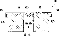
图6B示出沿图6A中I-I’线的剖视图;Figure 6B shows a sectional view along line I-I' in Figure 6A;
图7A示出又一改进的均衡构件的示例;Figure 7A shows an example of yet another improved equalization member;
图7B示出另一改进的均衡构件的另一示例。Fig. 7B shows another example of another improved equalization member.
具体实施方式Detailed ways
参照附图,本发明的优选实施例在下文中将详细描述,附图中,同类或相似的构件给予相同或类似的标号。另外,附图示出的热电元件装置和应用此热电元件装置的热电元件组件仅用于举例说明的目的。因此应注意附图并非限定而主要是概述实施例,而且并非旨在描绘所述实施例的特定参数或详细结构。Preferred embodiments of the present invention will be described in detail below with reference to the accompanying drawings, in which the same or similar components are given the same or similar reference numerals. In addition, the thermoelectric element device and the thermoelectric element assembly using the thermoelectric element device shown in the drawings are for illustrative purposes only. It should therefore be noted that the drawings are not limiting but mainly outline the embodiments and are not intended to depict specific parameters or detailed structures of the described embodiments.
第一实施例first embodiment
图1示出根据本发明第一实施例的一热电元件装置的示意图。如图所示,一热电元件装置100具有第一电极1,热电元件3,和第二电极2。FIG. 1 shows a schematic diagram of a thermoelectric element device according to a first embodiment of the present invention. As shown in the figure, a
所述第一电极1包括电极构件11,设置为与电极构件11的背面邻接的弹性构件12,和设置为与所述弹性构件12邻接的热均衡构件13。The first electrode 1 includes an
所述弹性构件12是导电的,因而组成所述第一电极1的一部分。所述弹性构件12具有预定的弹性,且优选为比所述热电元件3更易于变形。具体地,所述弹性构件12通常具有网状、栅格状、蜂巢状或诸如此类的格子状图案。在该实施例中,采用的所述弹性构件12由诸如细金属线网眼或类似物的铁丝网组成。The elastic member 12 is conductive and thus constitutes a part of the first electrode 1 . The elastic member 12 has predetermined elasticity, and is preferably more deformable than the
顺便指出,虽然组成所述弹性构件12的材料的固有弹性优选为大于那些组成所述热电元件3和所述电极构件11的材料的弹性,但也并不完全是这样。例如,所述弹性构件12可以通过被制备成上述形状,而比所述热电元件3更有弹性且与所述电极构件11具有相同或更大的弹性,而与其材料的固有弹性无关。Incidentally, although the inherent elasticity of the material constituting the elastic member 12 is preferably greater than those constituting the
另外,在该实施例中所述弹性构件12与所述电极构件11通过扩散结合而结合在一起。In addition, the elastic member 12 and the
所述热均衡构件13是导电的,因而组成所述第一电极的一部分。所述热均衡构件13优选构成为比所述热电元件3具有更好的热传导性。具体地,所述热均衡构件13由诸如金属箔或类似的薄板材料组成。更具体地说,所述热均衡构件13优选由铁、镍、钽、钛(titan)、钨、铜或碳的薄板组成,这些薄板相对便宜且具有高的热传导性。而且,可以由包含任一这些金属作为主要成分的物质、由所述物质和/或两种或多种的上述金属构成的合金、化合物或混合物构成所述热均衡构件13。此外,所述热均衡构件13可以由一薄板构成,该薄板通过添加两种或多种所述金属、所述材料、所述合金或诸如此类的物质而组成。这样,所述热均衡构件13的与所述弹性构件12接触的一面,优选为是与所述弹性构件12的组成物相同的物质构成。The
总的来说,所述热均衡构件13优选具有比所述弹性构件12更高的热传导率。为了使得热均衡构件13具有比所述弹性构件12更高的热传导率,组成所述热均衡构件13的材料的固有热传导率优选为高于构成所述弹性构件12的材料的热传导率,这也不完全如此。与材料本质的热传导率无关,当由于所述热均衡构件13形成板状、片状或诸如此类的形状,而所述弹性构件12形成网格或诸如此类的形状而使所述热均衡构件13比所述弹性构件12具有更好的热传导性时,结果所述热均衡构件13就具有更好的热传导率。In general, the
另外,所述热均衡构件13与所述弹性构件12接触或扩散结合。In addition, the
所述热电元件3由一对彼此分隔开的第一部分3A(被称为热电元件3A,下文中也是如此),和第二部分3B(被称为热电元件3B,下文中也是如此)构成,如图1所示。The
所述热电元件3A,3B由具有热电效应诸如伯珀耳帖效应、塞贝克效应或汤姆森效应的热电材料组成。具有这种效应的一种典型的物质,下列物质可作为热电半导体:具有铋和碲化合物为主要成分的物质、具有铋和锑化合物为主要成分的物质,具有填充方钴矿结构(a filled Skutteruditestructure)作为主相(primary phase)的物质,其中填充方钴矿结构中具有方钴矿晶体结构的CoSb3族化合物晶体中的孔隙(void)用化学元素填充,具有MgAgAs型晶体结构的半赫斯勒(Halfheusler)化合物作为主相的物质,和包含钡和镓的笼形(clathrate)化合物。另外,两种或多种这些物质的混合物可以用于组成所述热电元件3。此外,通过掺入包含上述每一物质的材料而得到的构件、任两种或多种这些物质的混合物,任两种或多种这些物质的化合物也可用来制备所述热电元件3。这些物质或类似物具有相对较低的热传导率。因此,当所述热电元件3A,3B由这些物质或类似物组成时,热梯度在所述热电元件3A,3B内容易维持,从而可以提高所述热电元件装置的性能。The
另外,这些热电半导体具有两种导电类型:N型导电型和P型导电型。在该实施例中,当所述热电元件3由一对所述热电元件3A和所述热电元件3B组成时,典型地这一对中的一个是N型,另一个是P型。In addition, these thermoelectric semiconductors have two conductivity types: N-type conductivity and P-type conductivity. In this embodiment, when the
所述热电元件3A,3B被设置成与所述第一电极1的所述热均衡构件13接触,但不是结合或粘结于其上。即,所述热电元件3A,3B仅仅与所述热均衡元件13保持接触。The
对应于由两个部分组成的所述热电元件3,所述第二电极2包括放置成与所述热电元件3A接触的第一部分2A(被称作第二电极2A,下文也是如此)和放置成与所述热电元件3B接触的第二部分2B(被称作第二电极2B,下文也是如此)。在该实施例中,利用结合构件8例如焊料,所述第二电极2A和所述热电元件3A接合,所述第二电极2B和所述热电元件3B接合。Corresponding to the
顺便指出,由于为叙述方便图1中说明的所述第一电极11安置在上,所述弹性构件12放置在所述第一电极的底面。然而如图1所示的所述热电元件装置翻转过来的话,很明显所述弹性部件12放置在所述电构件11上且所述热均衡构件13放置在所述弹性部件12上。此外,也很明显,所述热电元件3A,3B放置在所述第一电极1的上方。Incidentally, since the
根据上述结构,当一直流电压施加在所述第二电极2A,2B上,从而在它们之间流过一直流电流时,所述第一电极1或所述第二电极2的任一个可作为散热表面,另一个作为吸热表面。因此,通过调节电流,所述热电元件装置100可作为一温度控制器。另外,所述热电元件装置100能作为温度测量设备。即,由于根据在所述第一电极1和所述第二电极2A,2B间的温度差而在第一电极1和所述第二电极2A,2B间产生电压,通过电压可测量所述温度。According to the above structure, when a direct current voltage is applied to the
如前所述,当所述热电元件装置100运行时,将产生不均匀的温度分布,这将产生热应力,其源自在所述热电元件装置100内的热膨胀系数的差异。As mentioned before, when the
然而,在该实施例中,由于所述弹性构件12是由基于诸如细金属线网格的铁丝网组成,从而具有比所述热电元件3更高的弹性和具有与所述电极构件11相同或更高的弹性,因而所述热应力能被减小。换句话说,所述弹性部件12用于减小由于在所述电极构件11和所述热电元件3A,3B间热系数差异产生的热应力。因此,诸如由于所述热应力而导致的热电元件装置100内的破损和所述热电元件3A,3B的劣化等问题消除了。顺便指出,由于所述热均衡构件13仅仅与所述热电元件3接触,因此所述热均衡构件13和所述热电元件3能相对移动,进一步减小了所述热应力。However, in this embodiment, since the elastic member 12 is composed of a barbed wire mesh based on such as a fine metal wire grid, it has higher elasticity than the
所述热均衡构件13和所述弹性构件12结合或接触,且与所述热电元件3接触。另外,所述热均衡构件13比起所述弹性构件12和所述热电元件3有更高的热传导性。因此,所述热均衡构件13能够将从所述弹性构件12二维地传来的热能均匀地扩散到整个所述热均衡构件13本身,以进而将所述热均匀传导到所述热电元件3。The
如果所述弹性构件12能直接和所述热电元件3A,3B接触,在所述热电元件3A,3B和具有用于维持其弹性的网格状或类似形状的格子状图案的所述弹性构件12间的真正的接触面积将变小,这将导致阻碍热传导或恶化热均匀性等问题产生。然而,由于所述热均衡构件13的优异热传导性,所述热电元件装置100可以改善在所述弹性构件12和所述热电元件3A,3B间接触面积的热均匀性,从而提高热电换能的效率。If the elastic member 12 can be in direct contact with the
顺便指出,虽然该第一实施例例示了所述的热电元件3由一对所述第一部分3A和所述第二部分3B组成,所述热电元件3还可以由采用热电材料的单一件组成,相应的所述第二电极也可以由单一件组成。这种结构可作为热电元件装置操作,且在其它零件上没有区别,因此呈现前述的效果。Incidentally, although this first embodiment exemplifies that the
第二实施例second embodiment
图2示出根据本发明第二实施例的热电元件装置的示意图。如图所示,根据该第二实施例的热电元件装置200由第一电极10,热电元件3和第二电极2组成。Fig. 2 shows a schematic diagram of a thermoelectric element device according to a second embodiment of the present invention. As shown in the figure, the
所述第二电极2由第一部分2A(被称为第二电极2A,下文中也是如此)和第二部分2B(被称为第二电极2B,下文中也是如此)构成,这两部分彼此分离。具体地,所述第二电极2A通过在电极构件21A依次安置弹性构件22A和均衡构件23A而形成。类似地,所述第二电极2B通过在电极构件21B上依次设置弹性构件22B和均衡构件23B而形成。The
所述电极构件21A、21B,所述弹性构件22A、22B和所述均衡构件23A、23B分别由与第一实施例中制备电极构件11,弹性构件12和均衡构件13的材料相同的材料构成。另外,所述电极材料21A、21B和所述弹性构件22A,22B接触或通过扩散结合而结合。此外,所述弹性构件22A,22B分别与所述均衡构件23A、23B接触或通过扩散结合而结合。The
所述热电元件3由在第一实施例中所列举的材料制成,且由一对第一部分3A(热电元件3A)和第二部分3B(热电元件3B)组成。在这种情况下,所述热电元件3A,3B中的一个具有P型导电类型,另一个为N型导电类型。所述热电元件3A安置在所述第二电极2A上以与所述均衡构件23A接触;所述热电元件3B安置在所述第二电极2B上以与所述均衡构件23B接触。所述热电元件3A,3B分别与所述均衡构件23A,23B保持接触,但没有结合或黏附到所述均衡构件23A,23B上,如同在第一实施例中所述热电元件3和所述均衡构件12的情况一样。所述热电元件3通过结合材料8与所述第一电极10连接起来。The
如前所述,所述第一电极1不是如第一实施例中由第一电极构件11,所述弹性构件12和所述均衡构件13组成,在所述热电元件装置200中是所述第二电极2由这些构件组成;且所述热电元件和所述均衡构件接触。基于这样的结构,所述热电元件装置200与根据第一实施例的所述热电元件装置100呈现出相同的效果。As mentioned above, the first electrode 1 is not composed of the
第三实施例third embodiment
图3示出根据本发明第三实施例的热电元件装置300的示意图。如图所示,第一电极1包括一电极构件11,设置为与所述电极构件11底面接触的弹性构件12,设置为与所述弹性构件12杰出的均衡构件13。第二电极2由一对第二电极2A,2B组成,该对第二电极互相隔离。在所述第二电极2A中在电极构件21A上依次设置有弹性构件22A和均衡构件23A;在所述第二电极2B中在电极构件21B上依次设置有弹性构件22B和均衡构件23B。FIG. 3 shows a schematic diagram of a
所述弹性构件12,22A,22B与相应的电极构件11,21A,21B互相接触,或例如通过扩散结合与相应的电极构件11,21A,21B相结合。另外,所述均衡构件13,23A,23B与相应的弹性构件12,22A,22B接触,或例如通过扩散结合与相应的弹性构件12,22A,22B相结合。The
所述热电元件3由与在第一和第二实施例中用于热电元件的材料相同的材料制成;且由第一部分3A(热电元件3A)和第二部分(热电元件3B)的一个P-N对组成。所述热电元件3A安置在所述第二电极2A上以与所述均衡构件23A接触;所述热电元件3B安置在所述第二电极2B上以与所述均衡构件23B接触。此外,所述第一电极1安置在所述热电元件3A,3B上以使得组成所述第一电极1的所述热均衡构件13与热电元件3A,3B接触。所述热电元件3A,3B与所述均衡构件13,23A,23B保持接触,但不结合或黏附到所述均衡构件13,23A,23B上。The
如前所述在所述热电元件装置300中,所述第一电极1和所述第二电极2都由所述电极构件,所述弹性构件和所述热均衡构件组成。所述热电元件3的顶面和底面与所述均衡构件接触。因此,在其2顶面和底面由于热膨胀系数的差别产生的热应力被减小了,且热均衡性被改善,从而提供更高的热电转换效率。As mentioned above, in the
第四实施例Fourth embodiment
图4示出根据本发明第四实施例的热电组件的示意图。如图所示,热电组件400由在二维上安置多个热电元件装置5组成。每一热电元件装置5包括第一电极1,第二电极2和热电元件3,热电元件3设置成与所述第一电极和第二电极电连接和热连接。所述第一电极1和/或所述第二电极2包括电极构件,安置在所述电极构件上的弹性构件和安置在所述弹性构件上的均衡构件。虽然图4示出所述热电元件装置5与据第一实施例中的所述热电元件装置100相同,所述热电元件装置5也可以分别是第二和第三实施例中所述的热电元件装置200,300。Fig. 4 shows a schematic diagram of a thermoelectric assembly according to a fourth embodiment of the present invention. As shown in the figure, the
另外,由外部电路传送到所述热电组件400或由所述热电组件400传送到外部电路的电能是通过两根电线4进行的,该电线4设置为连接到所述电极2。从图4中明显可知,每一热电元件装置5在所述电线4和4间串联排列。因此,当一直流电压加载到所述电线4,4时,一电流流经所述第二电极2,所述热电元件3B,所述第一电极1,所述热电元件3A,所述第二电极2,所述热电元件3B......。这样,所述第一电极1和所述第二电极2中的一个可作为散热表面,另一个则作为吸热表面。In addition, the electric energy transmitted to or from the
如前所述,在所述热电组件400中,所述第一电极1和/或所述第二电极2由所述电极构件,设置于所述电极构件上的所述弹性构件,设置于所述弹性构件上的所述均衡构件构成,并且所述热电元件3与所述均衡构件接触。因此基于所述弹性构件的热膨胀系数的差别而产生的热应力被减小,并且基于所述热均衡构件热均衡性被提高,从而提供了具有改善的热电转换效率的热电组件。As mentioned above, in the
结合优选实施例已经详细描述了本申请,所述优选实施例仅仅旨在阐明本发明而非意欲限制本发明范畴。例如,当所述弹性构件与所述电极构件扩散结合,并且所述均衡构件与所述弹性构件扩散结合时,除了扩散结合外,该结合还可以通过使用具有银作为主要成分的金属焊料,具有钛(titan)作为主要成分的金属焊料,具有铜作为主要成分的金属焊料,具有钯作为主要成分的金属焊料,具有镍作为主要成分的金属焊料,包含铝的金属焊料,包含镁的金属焊料,包含铋的焊料,以及无铅焊料来执行。此外,只要电连接和热连接不被恶化,所述结合不限于以上所述。The present application has been described in detail with reference to the preferred embodiments, which are only intended to illustrate the present invention and are not intended to limit the scope of the present invention. For example, when the elastic member is diffusely bonded to the electrode member, and the equalizing member is diffusely bonded to the elastic member, in addition to diffusion bonding, the bonding can also be achieved by using metal solder having silver as a main component. Metal solder having titanium (titan) as a main component, metal solder having copper as a main component, metal solder having palladium as a main component, metal solder having nickel as a main component, metal solder containing aluminum, metal solder containing magnesium, Solder containing bismuth, as well as lead-free solder to perform. Furthermore, the combination is not limited to the above as long as the electrical connection and thermal connection are not deteriorated.
虽然第一和第二实施例例示了作为结合材料8的焊料,但该结合材料不仅限于焊料,只要在所述热电元件装置的工作温度下结合的质量不被恶化。例如结合材料8可以是导电粘合剂或金属焊料,如银蜡(silver wax)等。Although the first and second embodiments exemplify solder as the
此外,虽然已经例举了网状,栅格或蜂巢状的格子状图案作为所述弹性构件的形状,从前面的说明中可以很明显得出所述形状不限于这些图案。勿需多言,即便一平板状的也可与所述弹性构件有相同的效果。Furthermore, although a mesh, grid or honeycomb lattice pattern has been exemplified as the shape of the elastic member, it is apparent from the foregoing description that the shape is not limited to these patterns. Needless to say, even a flat plate can have the same effect as the elastic member.
虽然平板状已经被例示为所述均衡构件的形状,所述均衡构件还可以具有如图5,6中所示的形状,只要其与所述热电元件的接触面为平板形。即,如图5A所示,所述均衡构件130可以具有与所述热电元件3A接触的第一平板部分131,与所述热电元件3B接触的第二平板部分132和提供在第一平板部分131和第二平板部分132之间的弯曲部分133。在这样的形状上可以均匀地散布来自所述弹性构件(图5,6中未示出)的热量,进而传送热到所述热电元件3,正如在第一到第四实施例中的均衡构件一样。另外,所述弯曲部分133制成可变形的,从而辅助减小所述热应力。顺便指出,虽然所述弯曲部分133在图5A中具有U形,但是所述弯曲部分133并不仅限于U形。例如,所述弯曲部分可以是V形或W形。Although the shape of a flat plate has been exemplified as the shape of the equalizing member, the equalizing member may also have a shape as shown in Figs. 5 and 6 as long as its contact surface with the thermoelectric element is flat. That is, as shown in FIG. 5A , the equalizing
另外,如图5B所示,所述第一平板部分131和所述第二平板部分132可以具有垂悬部分134,其沿着与设置有所述弯曲部分133的边缘相对的边缘向下延伸。此外,如图6A和6B所示,在与设置有所述垂悬部件134的边缘相邻的两个边缘的每一个上可以分别设置另外的一个垂悬部分135。In addition, as shown in FIG. 5B , the first
此外,如图7A所示,所述垂悬部分134可以置于如图1和图3所示的所述平板状均衡构件13上;如图7B所示,所述垂悬部分134和所述垂悬部分135都可以置于如图1和图3所示的所述平板状均衡构件13上。另外,再上述情况中也可仅仅提供垂悬部分135。In addition, as shown in Figure 7A, the hanging
虽然图4示出了由17个热电元件装置组成的热电组件,勿需多言,所述热电组件中使用的所述热电元件装置的数目不限定为17个。另外,每个热电元件装置的布局不仅限于所示出的图例。Although FIG. 4 shows a thermoelectric assembly composed of 17 thermoelectric element devices, needless to say, the number of the thermoelectric element devices used in the thermoelectric assembly is not limited to 17. In addition, the layout of each thermoelectric element device is not limited to the illustration shown.
顺便指出,虽然第四实施例中例证了所述热电组件具有的二维地排列的热电元件装置是由一对N型导电部分和P型导电部分组成,所述热电组件也可以由具有单一件热电元件的热电元件装置组成。即在这种的热电元件装置中,所述热电元件是由一N型导电部分或一P型导电部分组成;从而,所述第一电极1和所述第二电极2由单一件组成。当所述热电组件是由具有这种结构的所述热电元件装置组成时,对于本领域的技术人员来说可以理解多个所述热电元件装置相互并联。另外,由于在每一热电元件装置中的所述第一电极和/或所述第二电极由所述电极构件,所述弹性构件,所述均衡构件组成,具有这种结构的所述热电组件可以很显著地减小热应力和提高热电转换效率。Incidentally, although it is exemplified in the fourth embodiment that the thermoelectric element device that the thermoelectric assembly has two-dimensionally arranged is composed of a pair of N-type conductive parts and P-type conductive parts, the thermoelectric assembly may also be composed of a single piece Thermoelectric elements are composed of thermoelectric element devices. That is, in this kind of thermoelectric element device, the thermoelectric element is composed of an N-type conductive part or a P-type conductive part; thus, the first electrode 1 and the
Claims (11)
Applications Claiming Priority (2)
| Application Number | Priority Date | Filing Date | Title |
|---|---|---|---|
| JP247915/2005 | 2005-08-29 | ||
| JP2005247915A JP4728745B2 (en) | 2005-08-29 | 2005-08-29 | Thermoelectric device and thermoelectric module |
Publications (1)
| Publication Number | Publication Date |
|---|---|
| CN1925183A true CN1925183A (en) | 2007-03-07 |
Family
ID=37715762
Family Applications (1)
| Application Number | Title | Priority Date | Filing Date |
|---|---|---|---|
| CNA2006101265804A Pending CN1925183A (en) | 2005-08-29 | 2006-08-29 | Thermoelectric element device and thermoelectric module |
Country Status (4)
| Country | Link |
|---|---|
| US (1) | US8110736B2 (en) |
| JP (1) | JP4728745B2 (en) |
| CN (1) | CN1925183A (en) |
| DE (1) | DE102006040283B4 (en) |
Cited By (6)
| Publication number | Priority date | Publication date | Assignee | Title |
|---|---|---|---|---|
| CN102648538A (en) * | 2009-11-03 | 2012-08-22 | 巴斯夫欧洲公司 | Use of porous metallic materials as contact connection in thermoelectric modules |
| CN102742040A (en) * | 2010-03-25 | 2012-10-17 | 京瓷株式会社 | Thermoelectric element and thermoelectric module |
| CN101952985B (en) * | 2008-01-23 | 2012-11-21 | 弗劳恩霍弗应用技术研究院 | Method for producing thermoelectric components and thermoelectric components |
| CN103460421A (en) * | 2011-04-06 | 2013-12-18 | 松下电器产业株式会社 | Thermoelectric conversion element module and method of manufacturing the same |
| CN103534566A (en) * | 2011-05-19 | 2014-01-22 | 株式会社伏沃 | Method of Measuring Temperature Using Thermistor |
| WO2017162196A1 (en) * | 2016-03-23 | 2017-09-28 | 刘光辰 | Thermoelectric conversion module, novel internal combustion engine, novel electric motor and power generation method |
Families Citing this family (24)
| Publication number | Priority date | Publication date | Assignee | Title |
|---|---|---|---|---|
| JP2008305987A (en) * | 2007-06-07 | 2008-12-18 | Sumitomo Chemical Co Ltd | Thermoelectric conversion module |
| JP5159264B2 (en) * | 2007-11-15 | 2013-03-06 | 株式会社東芝 | Thermoelectric device and thermoelectric module |
| JP5075707B2 (en) * | 2008-03-27 | 2012-11-21 | 株式会社東芝 | Thermoelectric device and thermoelectric module |
| CN101447548B (en) * | 2008-12-26 | 2011-03-30 | 中国科学院上海硅酸盐研究所 | Method for making thermoelectric devices |
| JP5066167B2 (en) * | 2009-12-10 | 2012-11-07 | 株式会社東芝 | Thermoelectric device and thermoelectric module |
| DE102010000660A1 (en) * | 2010-01-04 | 2011-07-07 | TEC COM GmbH Gesellschaft für Technik, Technologie & Vermarktung, 06128 | Thermoelectric generator has P-type and N-type elements that are provided at warm and cold side of generator stand over electrical and heat conducting metal bridges |
| DE102010035151A1 (en) * | 2010-08-23 | 2012-02-23 | Emitec Gesellschaft Für Emissionstechnologie Mbh | Semiconductor element for a thermoelectric module and method for its production |
| JP5656295B2 (en) * | 2011-04-22 | 2015-01-21 | パナソニックIpマネジメント株式会社 | Thermoelectric conversion module and manufacturing method thereof |
| FR2994025B1 (en) * | 2012-07-24 | 2015-04-10 | Valeo Systemes Thermiques | ELECTRIC THERMO MODULE |
| DE102012214702A1 (en) | 2012-08-17 | 2014-02-20 | Behr Gmbh & Co. Kg | Thermoelectric device |
| DE102012214704A1 (en) | 2012-08-17 | 2014-03-27 | Behr Gmbh & Co. Kg | Thermoelectric module |
| DE102012214701A1 (en) | 2012-08-17 | 2014-02-20 | Behr Gmbh & Co. Kg | Thermoelectric device |
| JP5928599B2 (en) * | 2012-09-19 | 2016-06-01 | 富士通株式会社 | Power generation device, measuring device and measuring system |
| US8956905B2 (en) * | 2013-02-01 | 2015-02-17 | Berken Energy Llc | Methods for thick films thermoelectric device fabrication |
| JP6171513B2 (en) * | 2013-04-10 | 2017-08-02 | 日立化成株式会社 | Thermoelectric conversion module and manufacturing method thereof |
| JP6193709B2 (en) * | 2013-09-30 | 2017-09-06 | 日本サーモスタット株式会社 | Thermoelectric conversion module |
| JP6278879B2 (en) * | 2014-10-29 | 2018-02-14 | アイシン高丘株式会社 | Thermoelectric module |
| WO2016190001A1 (en) * | 2015-05-27 | 2016-12-01 | 富士フイルム株式会社 | Thermoelectric conversion module and vehicle exhaust pipe |
| DE102015224020B4 (en) * | 2015-12-02 | 2019-05-23 | Deutsches Zentrum für Luft- und Raumfahrt e.V. | Thermoelectric module |
| KR102442799B1 (en) * | 2016-01-13 | 2022-09-14 | 엘지이노텍 주식회사 | thermoelectric element |
| JP6933441B2 (en) * | 2016-03-10 | 2021-09-08 | 株式会社アツミテック | Thermoelectric conversion module |
| US20190371995A1 (en) * | 2018-05-29 | 2019-12-05 | Faurecia Automotive Seating, Llc | Thermoelectric device with parallel elements |
| KR102872812B1 (en) * | 2021-07-12 | 2025-10-21 | 엘지이노텍 주식회사 | Thermoelectric module |
| US20220271370A1 (en) * | 2022-05-10 | 2022-08-25 | University Of Electronic Science And Technology Of China | Intelligent thermoelectric-battery integrated structure |
Family Cites Families (12)
| Publication number | Priority date | Publication date | Assignee | Title |
|---|---|---|---|---|
| JP3482094B2 (en) * | 1997-02-13 | 2003-12-22 | 財団法人電力中央研究所 | Thermal stress relaxation pad for thermoelectric conversion element and thermoelectric conversion element |
| JP3600486B2 (en) * | 1999-08-24 | 2004-12-15 | セイコーインスツル株式会社 | Manufacturing method of thermoelectric conversion element |
| US6347521B1 (en) * | 1999-10-13 | 2002-02-19 | Komatsu Ltd | Temperature control device and method for manufacturing the same |
| JP3962194B2 (en) * | 2000-01-20 | 2007-08-22 | 財団法人電力中央研究所 | Thermoelectric generator module |
| JP2002246659A (en) | 2001-02-14 | 2002-08-30 | Komatsu Ltd | Thermoelectric module |
| JP2002255561A (en) * | 2001-02-23 | 2002-09-11 | Ricoh Co Ltd | CoSb3-based compound having filled skutterudite structure, method for producing the same, and thermoelectric conversion material containing this CoSb3-based compound |
| US6921469B2 (en) * | 2002-03-26 | 2005-07-26 | Lattice Energy Llc | Electrode constructs, and related cells and methods |
| JP4488778B2 (en) * | 2003-07-25 | 2010-06-23 | 株式会社東芝 | Thermoelectric converter |
| JP2005116746A (en) * | 2003-10-07 | 2005-04-28 | Toshiba Corp | Thermoelectric conversion material and thermoelectric conversion element using the same |
| JP2005183528A (en) * | 2003-12-17 | 2005-07-07 | Toyota Motor Corp | Thermoelectric conversion element and manufacturing method thereof |
| JP4446064B2 (en) * | 2004-07-07 | 2010-04-07 | 独立行政法人産業技術総合研究所 | Thermoelectric conversion element and thermoelectric conversion module |
| JP2007035974A (en) * | 2005-07-27 | 2007-02-08 | Aisin Seiki Co Ltd | Thermoelectric converter |
-
2005
- 2005-08-29 JP JP2005247915A patent/JP4728745B2/en not_active Expired - Fee Related
-
2006
- 2006-08-24 US US11/466,975 patent/US8110736B2/en not_active Expired - Fee Related
- 2006-08-29 DE DE102006040283.9A patent/DE102006040283B4/en not_active Expired - Fee Related
- 2006-08-29 CN CNA2006101265804A patent/CN1925183A/en active Pending
Cited By (11)
| Publication number | Priority date | Publication date | Assignee | Title |
|---|---|---|---|---|
| CN101952985B (en) * | 2008-01-23 | 2012-11-21 | 弗劳恩霍弗应用技术研究院 | Method for producing thermoelectric components and thermoelectric components |
| CN102648538A (en) * | 2009-11-03 | 2012-08-22 | 巴斯夫欧洲公司 | Use of porous metallic materials as contact connection in thermoelectric modules |
| CN102742040A (en) * | 2010-03-25 | 2012-10-17 | 京瓷株式会社 | Thermoelectric element and thermoelectric module |
| CN102742040B (en) * | 2010-03-25 | 2016-03-23 | 京瓷株式会社 | Thermoelectric element and electrothermal module |
| CN103460421A (en) * | 2011-04-06 | 2013-12-18 | 松下电器产业株式会社 | Thermoelectric conversion element module and method of manufacturing the same |
| US9024173B2 (en) | 2011-04-06 | 2015-05-05 | Panasonic Intellectual Property Management Co., Ltd. | Thermoelectric conversion element module and method of manufacturing the same |
| CN103460421B (en) * | 2011-04-06 | 2016-05-18 | 松下知识产权经营株式会社 | Thermoelectric conversion element module and manufacture method thereof |
| CN103534566A (en) * | 2011-05-19 | 2014-01-22 | 株式会社伏沃 | Method of Measuring Temperature Using Thermistor |
| CN103534566B (en) * | 2011-05-19 | 2015-12-23 | 株式会社伏沃 | Method of Measuring Temperature Using Thermistor |
| WO2017162196A1 (en) * | 2016-03-23 | 2017-09-28 | 刘光辰 | Thermoelectric conversion module, novel internal combustion engine, novel electric motor and power generation method |
| CN108028305A (en) * | 2016-03-23 | 2018-05-11 | 北京山沃新能源科技有限公司 | Thermo-electric conversion module, internal combustion engine, New-type electric machine and electricity-generating method |
Also Published As
| Publication number | Publication date |
|---|---|
| JP2007066987A (en) | 2007-03-15 |
| DE102006040283B4 (en) | 2015-09-10 |
| JP4728745B2 (en) | 2011-07-20 |
| US8110736B2 (en) | 2012-02-07 |
| US20070044828A1 (en) | 2007-03-01 |
| DE102006040283A1 (en) | 2007-03-01 |
Similar Documents
| Publication | Publication Date | Title |
|---|---|---|
| CN1925183A (en) | Thermoelectric element device and thermoelectric module | |
| JP5956608B2 (en) | Thermoelectric module | |
| CN101040392A (en) | Thermoelectric conversion module, thermoelectric power generating apparatus and method using same | |
| JP7204779B2 (en) | semiconductor equipment | |
| US9997432B2 (en) | Semiconductor device and electronic component using the same | |
| WO2005124882A1 (en) | Thermoelectric conversion module | |
| CN1574316A (en) | Semiconductor unit with cooling system | |
| CN1551340A (en) | Semiconductor device and manufacturing method thereof | |
| CN103515522A (en) | Thermoelectric cooling module and manufacturing method thereof | |
| JP2012033559A (en) | Semiconductor device | |
| KR102487432B1 (en) | Heat conversion device | |
| JP2018064362A (en) | Semiconductor device | |
| JP2003282969A (en) | Thermoelectric conversion module | |
| JP5653455B2 (en) | Thermoelectric conversion member | |
| CN1744338A (en) | Thermoelectric device and method of manufacturing the same | |
| JP6507745B2 (en) | Thermoelectric conversion module | |
| CN1802741A (en) | Semiconductor device | |
| KR101508793B1 (en) | Manufacturing method of heat exchanger using thermoelectric module | |
| KR20180128186A (en) | Thermoelectric module | |
| JP2018125462A (en) | Graphite heatsink | |
| US20200006614A1 (en) | Thermoelectric conversion device | |
| JP2008085309A (en) | Thermoelectric conversion module, method for producing the same, and thermoelectric conversion material used for thermoelectric conversion module | |
| JP2007048916A (en) | Thermoelectric module | |
| JP2003318455A (en) | Peltier device and manufacturing method thereof | |
| JP2017069443A (en) | Thermoelectric conversion module |
Legal Events
| Date | Code | Title | Description |
|---|---|---|---|
| C06 | Publication | ||
| PB01 | Publication | ||
| C10 | Entry into substantive examination | ||
| SE01 | Entry into force of request for substantive examination | ||
| C12 | Rejection of a patent application after its publication | ||
| RJ01 | Rejection of invention patent application after publication |
Open date: 20070307 |