CN1947611B - Buckle - Google Patents
Buckle Download PDFInfo
- Publication number
- CN1947611B CN1947611B CN200610152189.1A CN200610152189A CN1947611B CN 1947611 B CN1947611 B CN 1947611B CN 200610152189 A CN200610152189 A CN 200610152189A CN 1947611 B CN1947611 B CN 1947611B
- Authority
- CN
- China
- Prior art keywords
- head
- plate
- sidewall
- sun
- base plate
- Prior art date
- Legal status (The legal status is an assumption and is not a legal conclusion. Google has not performed a legal analysis and makes no representation as to the accuracy of the status listed.)
- Active
Links
Images


Classifications
-
- A—HUMAN NECESSITIES
- A44—HABERDASHERY; JEWELLERY
- A44B—BUTTONS, PINS, BUCKLES, SLIDE FASTENERS, OR THE LIKE
- A44B11/00—Buckles; Similar fasteners for interconnecting straps or the like, e.g. for safety belts
- A44B11/25—Buckles; Similar fasteners for interconnecting straps or the like, e.g. for safety belts with two or more separable parts
-
- A—HUMAN NECESSITIES
- A44—HABERDASHERY; JEWELLERY
- A44B—BUTTONS, PINS, BUCKLES, SLIDE FASTENERS, OR THE LIKE
- A44B11/00—Buckles; Similar fasteners for interconnecting straps or the like, e.g. for safety belts
- A44B11/25—Buckles; Similar fasteners for interconnecting straps or the like, e.g. for safety belts with two or more separable parts
- A44B11/26—Buckles; Similar fasteners for interconnecting straps or the like, e.g. for safety belts with two or more separable parts with push-button fastenings
- A44B11/263—Buckles; Similar fasteners for interconnecting straps or the like, e.g. for safety belts with two or more separable parts with push-button fastenings with a push-button acting perpendicularly to the main plane of the buckle
-
- A—HUMAN NECESSITIES
- A44—HABERDASHERY; JEWELLERY
- A44B—BUTTONS, PINS, BUCKLES, SLIDE FASTENERS, OR THE LIKE
- A44B11/00—Buckles; Similar fasteners for interconnecting straps or the like, e.g. for safety belts
- A44B11/25—Buckles; Similar fasteners for interconnecting straps or the like, e.g. for safety belts with two or more separable parts
- A44B11/26—Buckles; Similar fasteners for interconnecting straps or the like, e.g. for safety belts with two or more separable parts with push-button fastenings
- A44B11/266—Buckles; Similar fasteners for interconnecting straps or the like, e.g. for safety belts with two or more separable parts with push-button fastenings with at least one push-button acting parallel to the main plane of the buckle and perpendicularly to the direction of the fastening action
-
- Y—GENERAL TAGGING OF NEW TECHNOLOGICAL DEVELOPMENTS; GENERAL TAGGING OF CROSS-SECTIONAL TECHNOLOGIES SPANNING OVER SEVERAL SECTIONS OF THE IPC; TECHNICAL SUBJECTS COVERED BY FORMER USPC CROSS-REFERENCE ART COLLECTIONS [XRACs] AND DIGESTS
- Y10—TECHNICAL SUBJECTS COVERED BY FORMER USPC
- Y10T—TECHNICAL SUBJECTS COVERED BY FORMER US CLASSIFICATION
- Y10T24/00—Buckles, buttons, clasps, etc.
- Y10T24/40—Buckles
- Y10T24/4002—Harness
- Y10T24/4012—Clamping
- Y10T24/4016—Pivoted part or lever
-
- Y—GENERAL TAGGING OF NEW TECHNOLOGICAL DEVELOPMENTS; GENERAL TAGGING OF CROSS-SECTIONAL TECHNOLOGIES SPANNING OVER SEVERAL SECTIONS OF THE IPC; TECHNICAL SUBJECTS COVERED BY FORMER USPC CROSS-REFERENCE ART COLLECTIONS [XRACs] AND DIGESTS
- Y10—TECHNICAL SUBJECTS COVERED BY FORMER USPC
- Y10T—TECHNICAL SUBJECTS COVERED BY FORMER US CLASSIFICATION
- Y10T24/00—Buckles, buttons, clasps, etc.
- Y10T24/45—Separable-fastener or required component thereof [e.g., projection and cavity to complete interlock]
- Y10T24/45225—Separable-fastener or required component thereof [e.g., projection and cavity to complete interlock] including member having distinct formations and mating member selectively interlocking therewith
- Y10T24/45471—Projection having movable connection between components thereof or variable configuration
- Y10T24/45524—Projection having movable connection between components thereof or variable configuration including resiliently biased projection component or surface segment
-
- Y—GENERAL TAGGING OF NEW TECHNOLOGICAL DEVELOPMENTS; GENERAL TAGGING OF CROSS-SECTIONAL TECHNOLOGIES SPANNING OVER SEVERAL SECTIONS OF THE IPC; TECHNICAL SUBJECTS COVERED BY FORMER USPC CROSS-REFERENCE ART COLLECTIONS [XRACs] AND DIGESTS
- Y10—TECHNICAL SUBJECTS COVERED BY FORMER USPC
- Y10T—TECHNICAL SUBJECTS COVERED BY FORMER US CLASSIFICATION
- Y10T24/00—Buckles, buttons, clasps, etc.
- Y10T24/45—Separable-fastener or required component thereof [e.g., projection and cavity to complete interlock]
- Y10T24/45225—Separable-fastener or required component thereof [e.g., projection and cavity to complete interlock] including member having distinct formations and mating member selectively interlocking therewith
- Y10T24/45471—Projection having movable connection between components thereof or variable configuration
- Y10T24/45524—Projection having movable connection between components thereof or variable configuration including resiliently biased projection component or surface segment
- Y10T24/45529—Requiring manual force applied against bias to interlock or disengage
-
- Y—GENERAL TAGGING OF NEW TECHNOLOGICAL DEVELOPMENTS; GENERAL TAGGING OF CROSS-SECTIONAL TECHNOLOGIES SPANNING OVER SEVERAL SECTIONS OF THE IPC; TECHNICAL SUBJECTS COVERED BY FORMER USPC CROSS-REFERENCE ART COLLECTIONS [XRACs] AND DIGESTS
- Y10—TECHNICAL SUBJECTS COVERED BY FORMER USPC
- Y10T—TECHNICAL SUBJECTS COVERED BY FORMER US CLASSIFICATION
- Y10T24/00—Buckles, buttons, clasps, etc.
- Y10T24/45—Separable-fastener or required component thereof [e.g., projection and cavity to complete interlock]
- Y10T24/45225—Separable-fastener or required component thereof [e.g., projection and cavity to complete interlock] including member having distinct formations and mating member selectively interlocking therewith
- Y10T24/45602—Receiving member includes either movable connection between interlocking components or variable configuration cavity
- Y10T24/45623—Receiving member includes either movable connection between interlocking components or variable configuration cavity and operator therefor
Landscapes
- Buckles (AREA)
Abstract
本发明提供装在帆布背包、提包、衣物、头盔等的连接带或皮带上,用于连接上述连接带或皮带的带扣。本发明的带扣包括阳头和可拆卸地与阳头啮合的阴头,阳头具有阳头本体和第1结合装置,阴头用于收容第1结合装置并具有阴头本体和可旋转地结合于阴头本体并与第1结合装置啮合的第2结合装置。具有上述结构的带扣,结构简单,可以降低带扣的制造费用。不仅如此,通过轻轻按下阴头的第2结合装置即可以从阴头轻松地解除阳头。
The present invention provides a buckle for attaching to a connecting strap or a belt of a rucksack, a bag, clothing, a helmet, etc. The belt buckle of the present invention includes a male head and a female head detachably engaged with the male head. The male head has a male head body and a first coupling device. The female head is used to accommodate the first coupling device and has a female body and a rotatable The second coupling means combined with the female body and engaged with the first coupling means. The buckle with the above structure has a simple structure and can reduce the manufacturing cost of the buckle. Not only that, but the male head can be easily released from the female head by lightly pressing the second coupling device of the female head.
Description
【技术领域】【Technical field】
本发明涉及带扣,具体地说涉及装在帆布背包、提包、衣服等的连接带或皮带端部,连接上述连接带或皮带,同时可以调节连接带或皮带的长度,并可以轻松拆卸的带扣。The present invention relates to a belt buckle, in particular to a belt which is installed at the end of a connecting belt or a belt of a rucksack, a bag, clothes, etc., is connected to the above connecting belt or belt, and at the same time can adjust the length of the connecting belt or belt, and can be easily disassembled buckle.
【背景技术】【Background technique】
如上所述,带扣一般是指在帆布背包或提包等的连接带或皮带的端部装上一对阴头和阳头相互连接的连接装置,这种带扣是由塑料材料一体形成而弹性结合的。As mentioned above, a buckle generally refers to a connection device that a pair of female and male heads are connected to each other on the end of the connecting belt or belt of a rucksack or a bag. This buckle is integrally formed by plastic materials and is elastic. combined.
上述结构的以往带扣根据帆布背包、提包以及衣物等物品的使用用途或需要,有如图1所示结构的带扣,其阳头310两侧的结合腿312从阴头320的空腔322插入,与阴头320两侧开放的狭缝324连接,解体时只要对与狭缝324连接的结合腿312加压即可使阴头和阳头解体,即、阴头320形成狭缝324的开放型带扣300;另外还有一种带扣,其阳头前端的结合部插入到阴头本体内侧后与阴头内侧形成的结合部结合,解体时只要对阴头外形部形成的加压装置加压即可解体,即、阴头没有形成狭缝的非开放型带扣200。According to the use or needs of articles such as rucksacks, handbags and clothing, the conventional buckles of the above structure have a buckle with a structure as shown in Figure 1, and the coupling legs 312 on both sides of the male head 310 are inserted from the cavity 322 of the female head 320 , connected with the open slits 324 on both sides of the female head 320, when disassembling, the female head and the male head can be disassembled as long as the combined leg 312 connected to the slit 324 is pressed, that is, the female head 320 forms the opening of the slit 324 Type buckle 300; there is another kind of buckle, the joint part of the front end of the male head is inserted into the inner side of the female head body and then combined with the joint part formed on the inner side of the female head. It can be disassembled by pressing, that is, the
即,开放型带扣只需对与阴头狭缝324结合的阳头的结合腿312加压即可解体,而非开放型带扣200的阴头没有开放的狭缝,解体时只要对阴头外形部的一定部分加压即可解体。That is, the open-type buckle only needs to pressurize the joint leg 312 of the male head combined with the female slit 324 to disassemble, while the female head of the non-open-
如上所述,两种带扣根据用途和需要各自具有不同的功能,其中对非开放型带扣200最常见的形态,参照附图说明如下。即,图2是以往技术涉及的非开放型带扣200的分解立体图,图3a是沿图2中A-A’线的剖面示意图,图3b是沿图2中B-B’线的剖面示意图。如上所述,这些部件由阴头220和阳头250构成。As mentioned above, the two kinds of buckles have different functions according to the application and needs, and the most common form of the
如图所示,阴头220具有从前端开放的空腔221,上侧的上板222形成了加压部223,加压部223的3个表面与上板222分离,另一面与上板222成一体,形成了沟224。加压部223的下方相隔一定距离形成了结合腿的引导面225,结合腿的引导面225的前端分别形成了阴头的连接段226,能够与阳头250的连接部253结合。As shown in the figure, the
阳头250从本体两侧直线凸出形成了结合腿251,结合腿251的前端内侧具有

如上所述形成的以往非开放型带扣在结合时,阳头250两侧形成的一对结合腿251通过阴头220前端入口的空腔221插入,结合腿25l的前端面下段形成的连接部253沿阴头220的结合腿引导面225滑动插入,从而弹性安装于阴头220的引导面225前端形成的连接段226,以与连接段226相互结合。When the conventional non-open buckle formed as described above is combined, a pair of
之后,解除带扣时,只要对阴头220上段形成的加压部223加压,则与阳头250的解体弹性片254相互结合的阴头220的连接段226和阳头250的连接部253即可脱离,以使各部件相互分离。Afterwards, when the buckle is released, as long as the pressurizing
上述以往技术涉及的非开放型带扣200,由于各部件上形成的连接装置,即阴头220的连接段226和阳头250的连接部253在阴头220内部较远的地方连接,所以结合腿251结合到阴头220的空腔221内部时,不仅连接困难,而且连接强度较弱,可能出现安全事故,此外,由于阴头220的上板222形成的加压部223与上板222有3个面分离,且阳头250的结合腿251和解体弹性片254也分离,所以带扣的整体强度非常弱,长期使用时带扣很容易损毁。The
此外,上述非开放型带扣200是通过对阴头220的加压部223加压,进而对其下段的阳头250的解体弹性片254加压,以使各部件解体的,所以其结构复杂,因此不仅结合与解体很困难,而且制造成本也大大增加。In addition, the above-mentioned
【发明内容】【Content of invention】
本发明为解决上述以往技术存在的问题而提出,目的是提供简单化阳头和阴头结构,从而可以降低带扣制造费用的带扣。The present invention is proposed to solve the above-mentioned problems in the prior art, and the purpose is to provide a buckle that simplifies the structure of the male head and the female head, thereby reducing the manufacturing cost of the buckle.
本发明另一个目的是提供为阴头提供弹性部件,通过弹性部件的弹力使阳头坚固地结合于阴头,同时能够容易地将阳头从阴头解除的带扣。Another object of the present invention is to provide a buckle that provides an elastic member for the female head, the male head is firmly combined with the female head by the elastic force of the elastic member, and at the same time can easily release the male head from the female head.
本发明还有一个目的是提供具有漂亮外观的带扣。Yet another object of the present invention is to provide a buckle having an attractive appearance.
本发明还有一个目的是提供阳头与阴头结合时,能够最小化阳头和阴头之间的空间,从而能够防止异物进入上述空间的带扣。Still another object of the present invention is to provide a buckle capable of minimizing the space between the male and female parts when the male and female parts are combined, thereby preventing foreign matter from entering the space.
为实现上述目的,本发明提供上段解除型(top-release type)带扣,其包括具有阳头本体和第1结合装置的阳头;具有阴头本体和可旋转地结合于上述阴头本体并与第1结合装置啮合的第2结合装置,同时可拆卸地与阳头啮合的阴头。To achieve the above object, the present invention provides a top-release type buckle, which includes a male head with a male body and a first coupling device; a female body and a female body that is rotatably coupled to the female body and A second coupling means engaged with the first coupling means, while a female head detachably engages with the male head.
第1结合装置是从阳头本体伸长一定长度,上面至少形成有1个结合腿的引导板,上述引导板与阳头本体一体形成,在构成阳头本体的2个侧壁的另一端连接上述侧壁,而下面形成有加固肋(reinforcing rib),不仅为引导板提供刚性,而且收容部分阴头。The first coupling device is extended from the male body by a certain length, and there is at least one guide plate with a coupling leg formed on it. The guide plate is integrally formed with the male body and connected to the other end of the two side walls that constitute the male body. The above-mentioned side wall is formed with a reinforcing rib (reinforcing rib) below, which not only provides rigidity for the guide plate, but also accommodates part of the female head.
上述阳头本体包括2个侧壁、和在侧壁中间连接侧壁的第1横条、以及在侧壁一端连接侧壁的第2横条。The male head body includes two side walls, a first horizontal bar connecting the side walls in the middle of the side walls, and a second horizontal bar connecting the side walls at one end of the side walls.
上述引导板从阳头本体另一端只延伸一定长度,引导板包括与阴头本体的台阶部啮合的第1台阶部、以及与闭锁板侧壁一端形成的台阶部啮合的第2台阶部。The above-mentioned guide plate only extends a certain length from the other end of the male body, and the guide plate includes a first stepped portion engaged with the stepped portion of the female body, and a second stepped portion engaged with the stepped portion formed at one end of the side wall of the locking plate.
上述结合腿的剖面形状大致成三角形,具有与闭锁板的闭锁壁(latchingwall)啮合的结合面(engaging face)和在阳头插入到阴头时抬起闭锁壁所需的倾斜面。The cross-sectional shape of the engaging leg is roughly triangular, and has an engaging face to engage the latching wall of the latching plate and an engaging face to lift the latching wall when the male head is inserted into the female head.
上述结合腿与阳头本体的第1横条相隔一定长度形成,在阳头与阴头结合时,使闭锁壁位于阳头本体和结合腿之间。The combination leg is formed at a certain length from the first horizontal bar of the male head body, and when the male head is combined with the female head, the locking wall is located between the male head body and the combination leg.
上述第2结合装置包括与阴头本体一同收容阳头的第1结合装置的闭锁板、以及在闭锁板一端下方形成的与第1结合装置的结合腿啮合的闭锁壁。The second coupling device includes a locking plate of the first coupling device that accommodates the male head together with the female body, and a locking wall formed under one end of the locking plate to engage with the coupling leg of the first coupling device.
上述阴头本体包括引导阳头的引导板进行收容的底板、在底板侧方边缘一体形成的侧壁、以及在底板后方与底板相隔一定间隔,在侧壁之间延伸的连接带连接条。The above-mentioned female head body includes a bottom plate that guides the guide plate of the male head for receiving, a side wall integrally formed on the side edge of the bottom plate, and a connecting strip extending between the side walls at a certain distance from the bottom plate behind the bottom plate.
上述底板前端形成有边缘部(lip portion),在阳头与阴头结合时,上述边缘部与阳头加固肋啮合。A lip portion is formed at the front end of the bottom plate, and when the male head and the female head are combined, the lip portion engages with the reinforcing rib of the male head.
本发明还包括弹性部件,对可旋转地结合于阴头本体的闭锁板提供弹性支撑。The present invention also includes an elastic component to provide elastic support for the locking plate rotatably combined with the female body.
上述弹性部件为长方形板,可以通过将底板的一部分以一定长度切割而形成,使弹性部件向底板后方延伸,或者通过在注射成形阴头时,将弹性部件与底板一体注射成形。The above-mentioned elastic member is a rectangular plate, which can be formed by cutting a part of the base plate to a certain length, so that the elastic member extends to the rear of the base plate, or by integrally injecting the elastic member and the base plate during injection molding of the female head.
上述侧壁两端分别从底板前端以及后端延伸出一定长度,上述侧壁前端形成的延长部与底板前端形成的边缘部的端部对齐,上述延长部上形成有台阶部,当阳头与阴头结合时,上述台阶部与引导板的第1台阶部啮合。The two ends of the above-mentioned side wall respectively extend a certain length from the front end and the rear end of the bottom plate, the extension part formed at the front end of the above-mentioned side wall is aligned with the end of the edge part formed at the front end of the bottom plate, and a step part is formed on the above-mentioned extension part, when the male head and During female coupling, the above-mentioned stepped portion engages with the first stepped portion of the guide plate.
上述两侧壁的内表面中间部分形成有用于引导闭锁板铰链的铰链引导沟和能够可旋转地插入铰链的铰链孔,上述铰链引导沟从侧壁上段到铰链孔为止倾斜形成,具有与铰链孔的直径相对应的宽度。A hinge guide groove for guiding the lock plate hinge and a hinge hole capable of rotatably inserting the hinge are formed in the middle part of the inner surface of the two side walls. The hinge guide groove is formed obliquely from the upper section of the side wall to the hinge hole, and has a The diameter corresponds to the width.
上述闭锁板为平坦的平板,其长度与包含边缘部的阴头本体的底板长度相同,其宽度与阴头本体的侧壁之间宽度相同,上述闭锁板的两侧边缘部形成有侧壁,上述闭锁板前端向下延伸一定长度形成有闭锁壁,上述闭锁板的内表面形成有用于收容弹性部件自由端的沟。The above-mentioned locking plate is a flat plate, its length is the same as the length of the bottom plate of the female body including the edge, and its width is the same as the width between the side walls of the female body. Side walls are formed on both side edges of the above-mentioned locking plate, The front end of the locking plate extends downward for a certain length to form a locking wall, and the inner surface of the locking plate is formed with a groove for accommodating the free end of the elastic component.
上述侧壁的中间部分形成有从侧壁向外侧延伸一定长度的铰链,在与侧壁前端相隔一定距离的位置形成有台阶部,当阳头插入到阴头内时,台阶部与阳头的引导板上形成的第2台阶部相接。The middle part of the side wall is formed with a hinge extending from the side wall to the outside for a certain length, and a step part is formed at a certain distance from the front end of the side wall. When the male head is inserted into the female head, the step part and the male head The second step portion formed on the guide plate is in contact with each other.
具有上述结构的带扣,简化了阳头和阴头的结构,降低了带扣的制造成本。此外,阳头可以通过弹性部件的弹力牢固地与阴头结合。不仅如此,通过轻轻压下阴头的结合板就可以轻松地从阴头上解除阳头。阳头与阴头结合时,阳头与阴头之间的空间较小,因此能够防止异物进入上述空间。The buckle with the above structure simplifies the structure of the male head and the female head, and reduces the manufacturing cost of the buckle. In addition, the male head can be firmly combined with the female head through the elastic force of the elastic component. Not only that, but the male head can be easily released from the female head by gently pressing down the coupling plate of the female head. When the male head and the female head are combined, the space between the male head and the female head is small, so foreign matter can be prevented from entering the above-mentioned space.
如上所述,本发明涉及的带扣,阳头和阴头的结构简单,能够降低带扣制造费用。此外,在阳头和阴头结合时,阴头内部部件对阳头的抵抗较少。As mentioned above, in the buckle of the present invention, the structure of the male head and the female head is simple, which can reduce the manufacturing cost of the buckle. Also, when the male and female are combined, the internal parts of the female provide less resistance to the male.
另一方面,本发明涉及的带扣,通过对阴头提供弹性部件,利用弹性部件的弹力,能够将阳头牢固地结合于阴头。此外,在阳头与阴头结合的状态下,轻轻压下阴头的结合板,即可很容易地从阴头上解除阳头。On the other hand, in the buckle according to the present invention, by providing an elastic member to the female head, the male head can be firmly coupled to the female head by utilizing the elastic force of the elastic member. In addition, in the state where the male head is combined with the female head, the male head can be easily released from the female head by gently pressing down the joint plate of the female head.
此外,本发明涉及的带扣,不仅外观漂亮,而且阳头和阴头结合时,阳头和阴头之间的间隙较小,能够防止异物通过间隙进入到阴头内部。In addition, the buckle of the present invention not only has a beautiful appearance, but also when the male head and the female head are combined, the gap between the male head and the female head is small, which can prevent foreign matter from entering the inside of the female head through the gap.
【附图说明】【Description of drawings】
图1是以往技术涉及的侧面解除型(side-release type)带扣的分解立体图。Fig. 1 is an exploded perspective view of a side-release type buckle according to the prior art.
图2是以往技术涉及的上段解除型带扣的分解立体图。Fig. 2 is an exploded perspective view of an upper release type buckle according to the prior art.
图3a是沿图2中A-A’线截取的以往上段解除型带扣的剖面示意图,显示了结合的阴头和阳头。Fig. 3a is a schematic cross-sectional view of a conventional top release buckle taken along line A-A' in Fig. 2, showing the combined female and male ends.
图3b是沿图2中B-B’线截取的以往上段解除型带扣的剖面示意图,显示了结合的阴头和阳头。Fig. 3b is a schematic cross-sectional view of a conventional top release buckle taken along line B-B' in Fig. 2, showing the combined female and male ends.
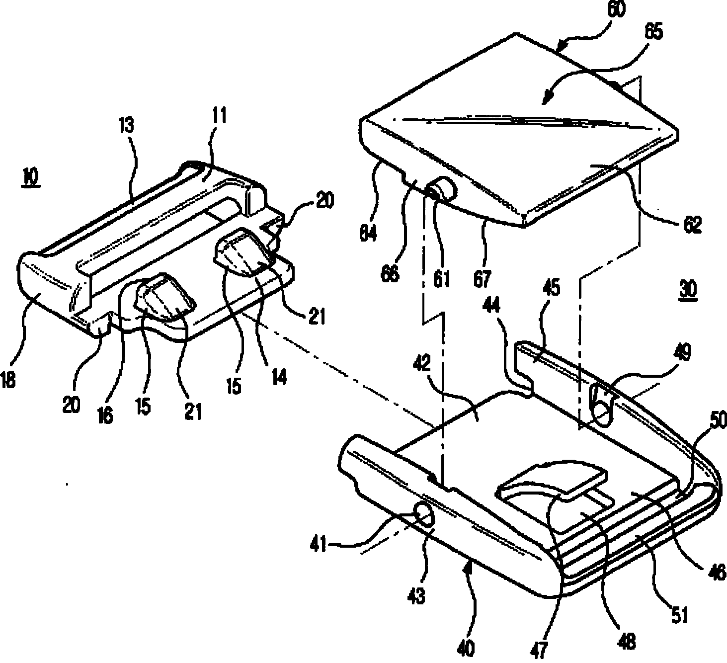
图4是本发明一个实施方式涉及的带扣的分解立体图。Fig. 4 is an exploded perspective view of the buckle according to the embodiment of the present invention.
图5是从其它方向看去的本发明一个实施方式涉及的带扣的分解立体图。Fig. 5 is an exploded perspective view of the buckle according to one embodiment of the present invention seen from another direction.
图6是本发明一个实施方式涉及的带扣的立体图,显示了阴头和阳头的结合状态。Fig. 6 is a perspective view of a buckle according to an embodiment of the present invention, showing a combined state of a female head and a male head.
图7是本发明一个实施方式涉及的带扣的立体图,显示了阴头和阳头的分离状态。Fig. 7 is a perspective view of a buckle according to an embodiment of the present invention, showing a separated state of a female head and a male head.
图8是图7所示带扣的平面示意图。Fig. 8 is a schematic plan view of the buckle shown in Fig. 7 .
图9是图7所示带扣的侧面示意图。Fig. 9 is a schematic side view of the buckle shown in Fig. 7 .
图10是图6所示带扣的剖面示意图。FIG. 10 is a schematic cross-sectional view of the buckle shown in FIG. 6 .
图11是本发明一个实施方式涉及的带扣的剖面示意图,说明阳头和阴头结合时阴头的作用。Fig. 11 is a schematic cross-sectional view of a buckle according to an embodiment of the present invention, illustrating the function of the female head when the male head and the female head are combined.
图12是本发明一个实施方式涉及的带扣的立体图,说明阳头和阴头分离时阴头的作用。Fig. 12 is a perspective view of a buckle according to an embodiment of the present invention, illustrating the function of the female part when the male part and the female part are separated.
图13是本发明一个实施方式涉及的带扣的剖面示意图,说明阳头和阴头分离时阴头的作用。Fig. 13 is a schematic cross-sectional view of a buckle according to an embodiment of the present invention, illustrating the function of the female part when the male part and the female part are separated.
【符号说明】【Symbol Description】
10:阳头, 11:阳头本体, 12:第1横条, 13:第2横条,10: Yang head, 11: Yang head body, 12: The first bar, 13: The second bar,
14:引导板, 15:结合腿, 16:结合面,14: guide plate, 15: joint leg, 16: joint surface,
17、50:连接带收容空间, 18、43:侧壁, 19:加固肋,17, 50: connecting belt accommodation space, 18, 43: side wall, 19: reinforcing rib,
20:第1台阶部, 21、67:倾斜面, 30: 阴头,20: the first step, 21, 67: inclined surface, 30: female head,
35:空腔, 40:阴头本体, 41:铰链孔, 42:边缘部,35: cavity, 40: female body, 41: hinge hole, 42: edge,
44:台阶部, 45:延长部, 46:底板, 47:弹性部件,44: step part, 45: extension part, 46: bottom plate, 47: elastic part,
48:贯通孔, 49:铰链引导沟, 51:连接带连接条,48: Through hole, 49: Hinge guide groove, 51: Connecting strip connecting strip,
60:闭锁板, 61:铰链, 62:加压部, 63:闭锁壁,60: Locking plate, 61: Hinge, 62: Pressure part, 63: Locking wall,
65:上表面, 66:侧壁, 71、72:连接带。65: Upper surface, 66: Side wall, 71, 72: Connecting strips.
【具体实施方式】【Detailed ways】
下面参照附图对本发明的优选实施方式进行详细说明。Preferred embodiments of the present invention will be described in detail below with reference to the accompanying drawings.
图4是本发明一个实施方式涉及的带扣的分解立体图;图5是从其它方向看去的本发明一个实施方式涉及的带扣的分解立体图;图6是本发明一个实施方式涉及的带扣的立体图,显示了阴头和阳头的结合状态;图7是本发明一个实施方式涉及的带扣的立体图,显示了阴头和阳头的分离状态;图8是图7所示带扣的平面示意图;图9是图7所示带扣的侧面示意图;图10是图6所示带扣的剖面示意图。Fig. 4 is an exploded perspective view of a buckle according to an embodiment of the present invention; Fig. 5 is an exploded perspective view of a buckle according to an embodiment of the present invention viewed from other directions; Fig. 6 is a perspective view of a buckle according to an embodiment of the present invention Fig. 7 is a perspective view of a buckle according to an embodiment of the present invention, showing a separated state of a female head and a male head; Fig. 8 is a diagram of the buckle shown in Fig. 7 Plan view; Figure 9 is a side view of the buckle shown in Figure 7; Figure 10 is a schematic cross-sectional view of the buckle shown in Figure 6.
如图4至图10所示,本发明涉及的带扣包括可拆分地结合的阳头10和阴头30。阳头10和阴头30一般由合成树脂制成,分别连接于连接带71、72或皮带的自由端。As shown in FIGS. 4 to 10 , the buckle according to the present invention includes a
阳头10包括阳头本体11及第1结合部14。第1结合部14是从阳头本体11延伸出一定长度且上面至少形成了1个结合腿15的引导板14。The
阳头10的阳头本体11包括2个侧壁18、在侧壁18中间连接侧壁18的第1横条12以及在侧壁18一端连接侧壁18的第2横条13。连接侧壁18的第1及第2横条12、13与连接带的一端连接,以使使用者能够调节连接带的长度。第1及第2横条12、13的截面形状成三角形或梯形。The
此外,引导板14与本体11一体形成,用于在构成阳头10本体11的2个侧壁18的另一端连接侧壁18。引导板14下面形成了加固肋19,不仅为引导板14提供刚性,而且用于收容后述的阴头30的边缘部42。In addition, the
引导板14从阳头本体11的另一端延伸出一定长度,并且包括与阴头30本体40的台阶部44啮合的第1台阶部20以及与闭锁板60侧壁66一端形成的台阶部啮合的第2台阶部。The
在引导板14上面,至少有1个结合腿15与引导板14一体形成。结合腿15的截面形状大致成三角形。结合腿15包括与闭锁板60的闭锁壁63啮合的结合面16和在阳头10插入到阴头30中时抬起闭锁壁63所需的倾斜面21。On the
结合腿15与阳头本体11的第1横条12相隔一定长度形成,用于在阳头10与阴头30结合时,使闭锁壁63位于阳头本体11和结合腿15之间。The connecting
此外,阳头10通过支撑形成阳头本体11的侧壁18、第1横条12、第2横条13以及引导板14的加固肋19,形成(define)了连接带收容部17。当将连接带71连接于阳头10时,连接带收容空间17能够稳定地收容连接带71。In addition, the
阴头30包括阴头本体40以及可旋转地结合于阴头本体40的第2结合部60。第2结合部60包括与阴头本体40一起收容阳头的第1结合部14(即引导板14)的闭锁板60以及在闭锁板60一端下方形成的与第1结合部14的结合腿15啮合的闭锁壁63。The
阴头30的阴头本体40包括引导阳头10的引导板14进行收容的底板46、在底板46侧方边缘一体形成的侧壁43、以及在底板46后方与底板46相隔一定间隔,在侧壁43之间延伸的连接带连接条51。The
底板46前端形成了边缘部42,在阳头10与阴头30结合时,边缘部42与阳头10的加固肋19啮合。An
此外,底板46还可以包括弹性支撑可旋转地结合于阴头本体40的闭锁板60的弹性部件47。弹性部件47为长方形板,可以通过将底板46的一部分只以一定长度切割,并使弹性部件向底板46后方延伸而形成,或者可以在注射成形阴头30时,将弹性部件与底板46一体注射成形。In addition, the
侧壁43两端分别从底板46前端以及后端只延伸出一定长度。侧壁43前端形成的延长部45与底板46前端形成的边缘部42的端部对齐。如图4、5、6、7以及9所示,侧壁43的延长部45上形成了台阶部44,当阳头10与阴头30结合时,台阶部44与引导板14的第1台阶部20啮合。Both ends of the
如图4所示,两侧壁43的内表面中间部分形成了引导闭锁板60铰链61的铰链引导沟49和能够可旋转地插入铰链61的铰链孔41。铰链引导沟49从侧壁43上段到铰链孔41为止倾斜形成,具有与铰链孔41的直径相对应的宽度。As shown in FIG. 4 , a
此外,连接带连接条51在从底板46后端只延伸一定长度而形成的侧壁43的另一端之间延伸。因此,在连接带连接条51上固定连接带或皮带的自由端或一端,即可将阴头30连接于连接带或皮带的自由端或一端。In addition, a connecting
闭锁板60为平坦的平板,其长度与包含边缘部42的阴头本体40的底板46的长度相同,其宽度与阴头本体40的侧壁43之间宽度相同。闭锁板60的两侧边缘部形成了侧壁66。闭锁板60前端向下只延伸一定长度形成了闭锁壁63。The locking
侧壁66的中间部分形成了从侧壁66向外侧只延伸一定长度的铰链61。此外,在与侧壁66前端相隔一定距离的位置形成了台阶部,当阳头10插入到阴头30内时,台阶部与阳头10的引导板14上形成的第2台阶部相接。The middle portion of the
此外,侧壁66从中间部位向后端形成了具有平缓的斜度的倾斜面67。因此,当要拆分与阴头30结合的阳头10时,只要轻轻压下闭锁板60后端,闭锁板60就会如图11所示,顺时针方向旋转。此时,通过具有一定斜度的侧壁66的倾斜面67,闭锁板60就会顺利地旋转。In addition, the
闭锁板60前端形成的闭锁壁63的厚度与阳头10本体11的另一端和结合腿15之间的间隔一致或稍薄。此外,闭锁壁63的内表面相对闭锁板60垂直形成,从而确保与结合腿15的结合面16牢固地啮合。The thickness of the locking
此外,闭锁板60的内表面形成有用于收容弹性部件47自由端的沟。因此,闭锁板60通过弹性部件47的弹力,以铰链61为中心,其后端压在上方,其前端压在下方。此时,闭锁板60通过闭锁板60的侧壁66一端支撑在阴头本体40的底板46上,成水平状态。In addition, a groove for accommodating the free end of the
下面参照附图对本发明优选实施方式涉及的带扣的作用进行详细说明。Hereinafter, the function of the buckle according to the preferred embodiment of the present invention will be described in detail with reference to the accompanying drawings.
首先,通过注射成形制作阳头10,使阳头10的本体11和引导板14成一体。至于阴头30,可以通过一体注射成形底板46、侧壁43以及弹性部件47来制作阴头本体40,或者通过在一体注射成形底板46及侧壁43后,切割底板46的一部分形成弹性部件47来制作阴头本体40。阴头30的闭锁板60也是通过注射成形制作的。First, the
接着,将闭锁板60的铰链61置于在阴头本体40侧壁43的内表面上形成的铰链引导沟49的入口处。然后,对闭锁板60施力,使铰链61沿铰链引导沟49向下移动插入到在阴头本体40侧壁43上形成的铰链孔41中。接着,组合阴头30的本体40和闭锁板60,使闭锁板60能够以铰链61为中心顺时针或逆时针旋转。Next, the
如上所述,制作并组合的阳头10和阴头30分别连接于皮带或连接带的两端,或分别连接于皮带。首先,阳头10使皮带的端部或连接带的一端从阳头10的连接带收容部17贯通第1横条12和引导板14之间的间隙,缠绕于第1横条12,贯通第1横条12和第2横条13之间的间隙而延伸,与皮带或连接带一端连接。As mentioned above, the fabricated and assembled
皮带的端部或连接带的一端以上述方式连接于阳头10,从而使用者可以适当地调节连接到阳头10的皮带或连接带的长度。此外,使用者在调节皮带或连接带的长度后,只要将阳头10和阴头30相互结合,阳头10的第2横条13就可以将皮带的端部或连接带的一端紧贴于皮带或连接带的其它部分,以防止皮带或连接带的长度随意改变。The end of the belt or one end of the connecting strap is connected to the
此外,阴头30连接于另一个皮带的端部或连接带的另一端。在阴头本体40的底板46和连接带连接条51之间的间隙中以一定长度贯通延伸,使另一个皮带的端部或连接带的另一端缠绕于连接带连接条51。接着,另一个皮带的端部或连接带另一端紧贴于另一个皮带的其它部分或连接带的其它部分后缝合,使阴头30固定连接于另一个皮带的端部或连接带的另一端。In addition, the
如上所述,只要结合连接到各种皮带或连接带两端的阳头10和阴头30,就可以适当调节连接的皮带或连接带的长度。As mentioned above, as long as the
此外,为了结合阳头10和阴头30,如图11和图12所示,要将阳头10的引导板14的前端置于由阴头30本体40和闭锁板60形成的空腔35的开口部。接着,压下阳头10本体11,使其插入到阴头30形成的空腔35内。In addition, in order to combine the
此时,阳头10的引导板14沿阴头30的底板46滑行,同时引导板14上面形成的结合腿15缓缓地将在阴头30闭锁板60上形成的闭锁壁63抬起。引导板14沿底板46继续滑行,使阳头10的加固肋19与底板46的边缘部42相接,与此同时闭锁板60通过弹性部件47的弹力逆时针方向旋转,使闭锁板60的闭锁壁63与结合腿15啮合。如上所述,通过闭锁壁63和结合腿15的啮合,使阳头10牢固地与阴头30结合。At this time, the
也可以通过不同方法将阳头10结合于阴头30。即,将阳头10的引导板14的前端置于由阴头30本体40和闭锁板60形成的空腔35的开口部。然后,压下阴头30的闭锁板60的后端,使闭锁板60顺时针方向旋转,扩张阴头30上形成的空腔35的开口,再将阳头10的引导板14压入阴头30的空腔35内。接着,利用弹性部件47的弹力使闭锁板60逆时针方向旋转,从而使闭锁板60的闭锁壁63与引导板14的结合腿15啮合。这样即可结合阳头10和阴头30。It is also possible to combine the
此外,当拆分相互结合的阴头10和阳头10时,如图13所示,下压闭锁板60的后端,以铰链61为中心顺时针方向旋转闭锁板60。这样即可解除闭锁板60的闭锁壁63和引导板14的结合腿15之间的结合状态。接着,将阳头10的引导板14从阴头30的空腔35中除去,从而解除阳头10和阴头30的结合。In addition, when disassembling the combined
参照本发明最佳实施方式对本发明进行了图示,并进行了详细说明,但具有相关领域通常知识的人在不脱离权利要求范围要求的本发明范围的情况下,可以对本发明进行多种变形。The present invention has been illustrated and described in detail with reference to the best mode of the present invention, but a person having ordinary knowledge in the relevant field can make various modifications to the present invention without departing from the scope of the present invention as claimed in the claims .
Claims (7)
Applications Claiming Priority (3)
| Application Number | Priority Date | Filing Date | Title |
|---|---|---|---|
| KR20-2005-0029057 | 2005-10-12 | ||
| KR2020050029057 | 2005-10-12 | ||
| KR2020050029057U KR200405410Y1 (en) | 2005-10-12 | 2005-10-12 | buckle |
Publications (2)
| Publication Number | Publication Date |
|---|---|
| CN1947611A CN1947611A (en) | 2007-04-18 |
| CN1947611B true CN1947611B (en) | 2011-04-06 |
Family
ID=37905496
Family Applications (1)
| Application Number | Title | Priority Date | Filing Date |
|---|---|---|---|
| CN200610152189.1A Active CN1947611B (en) | 2005-10-12 | 2006-09-18 | Buckle |
Country Status (5)
| Country | Link |
|---|---|
| US (1) | US7874049B2 (en) |
| JP (1) | JP2007105455A (en) |
| KR (1) | KR200405410Y1 (en) |
| CN (1) | CN1947611B (en) |
| DE (1) | DE102006045501B4 (en) |
Families Citing this family (31)
| Publication number | Priority date | Publication date | Assignee | Title |
|---|---|---|---|---|
| SE529698C2 (en) * | 2006-03-14 | 2007-10-30 | Joeran Lundh | Buckle |
| KR100833682B1 (en) * | 2006-04-27 | 2008-05-29 | 황종오 | Tying tool for shoelace |
| US20090094811A1 (en) * | 2007-10-10 | 2009-04-16 | Nifco Taiwan Corporation | Front release buckle |
| JP5134437B2 (en) * | 2008-05-28 | 2013-01-30 | 株式会社ニフコ | buckle |
| US8267614B2 (en) * | 2009-04-24 | 2012-09-18 | Toyota Motor Engineering & Manufacturing North America, Inc. | Easy install guide slot with snap tab |
| US8484814B2 (en) * | 2010-03-10 | 2013-07-16 | Illinois Tool Works Inc. | Three point release buckle |
| US20120096632A1 (en) * | 2010-10-21 | 2012-04-26 | First Rank Co., Ltd. | Swimming goggle and fastening assembly thereof |
| WO2013164888A1 (en) * | 2012-05-02 | 2013-11-07 | Ykk株式会社 | Front-release buckle |
| CN116764058A (en) | 2012-07-27 | 2023-09-19 | 瑞思迈私人有限公司 | Patient interface and methods used to manufacture it |
| US9072344B2 (en) * | 2013-06-18 | 2015-07-07 | Ying-Chuan Yen | Cover buckle structure |
| US9433259B2 (en) * | 2013-10-24 | 2016-09-06 | Bell Sports, Inc. | Self-actuating webbing adjuster and helmet strap system including same |
| KR101425027B1 (en) * | 2014-03-17 | 2014-08-01 | 주식회사 피엠씨엔에프 | Buckle using coilspring |
| USD799372S1 (en) * | 2016-01-12 | 2017-10-10 | Woojin Plastic Co., Ltd | Roller for webbing |
| DE102017115570B4 (en) | 2016-07-11 | 2019-10-17 | Vaude Gmbh & Co. Kg | Two-piece buckle with a fastener for fixing the buckle to a flat surface of a bag in particular a bicycle bag |
| USD805952S1 (en) * | 2016-08-02 | 2017-12-26 | Doskocil Manufacturing Company, Inc. | Buckle |
| USD814968S1 (en) * | 2016-09-06 | 2018-04-10 | Doskocil Manufacturing Company, Inc. | Buckle |
| USD814969S1 (en) * | 2016-09-06 | 2018-04-10 | Doskocil Manufacturing Company, Inc. | Buckle |
| CN110337263A (en) * | 2017-03-15 | 2019-10-15 | 泰尔茂株式会社 | Sphygmomanometer, cuff portion and sphygmomanometer main body |
| EP3434135A1 (en) * | 2017-07-26 | 2019-01-30 | MOPLAN, Studio za oblikovanje, d.o.o. | Buckle for luggage and pieces of luggage |
| US10219587B1 (en) * | 2017-09-05 | 2019-03-05 | Duraflex Hong Kong Limited | Attachment system with a connected article |
| SE541797C2 (en) * | 2017-11-30 | 2019-12-17 | Husqvarna Ab | Tool belt |
| US10791803B2 (en) * | 2018-01-12 | 2020-10-06 | National Molding Llc | Release lever buckle |
| DE202018102702U1 (en) | 2018-05-15 | 2018-05-22 | Stratic Lederwaren Jacob Bonifer Gmbh | Bag with self-aligning buckle |
| DE202018102768U1 (en) | 2018-05-17 | 2018-06-14 | Stratic Lederwaren Jacob Bonifer Gmbh | Bag with self-aligning buckle |
| CN109938459B (en) * | 2019-03-15 | 2022-07-22 | 苏州中科先进技术研究院有限公司 | Eye-splice connecting device |
| CN213154410U (en) * | 2020-05-12 | 2021-05-11 | 香港多耐福有限公司 | A buckle and belt |
| USD1021687S1 (en) * | 2020-05-12 | 2024-04-09 | Duraflex Hong Kong Limited | Buckle |
| DE102020115361A1 (en) | 2020-06-09 | 2021-12-09 | Edelrid Gmbh & Co. Kg | Two-part buckle for a chinstrap connection of a safety helmet |
| US11930895B2 (en) * | 2020-11-03 | 2024-03-19 | The Beer Vest Guys Llc | Garment for displaying ornaments |
| JP7606258B2 (en) * | 2021-08-24 | 2024-12-25 | 青▲島▼矢▲車▼菊▲設▼▲計▼有限公司 | Seat cushions and nursing chairs |
| US12201192B2 (en) * | 2023-04-26 | 2025-01-21 | Foshan Tuorun Precision Hardware Technology Co., Ltd | Connecting buckle with safety switch |
Citations (2)
| Publication number | Priority date | Publication date | Assignee | Title |
|---|---|---|---|---|
| CN1132055A (en) * | 1994-11-18 | 1996-10-02 | Ykk株式会社 | Buckle |
| CN1550168A (en) * | 2003-05-07 | 2004-12-01 | 株式会社利富高 | Buckle |
Family Cites Families (17)
| Publication number | Priority date | Publication date | Assignee | Title |
|---|---|---|---|---|
| US3600768A (en) * | 1969-02-26 | 1971-08-24 | Irvin Industries Inc | Integral three-point safety buckle |
| DE7126101U (en) * | 1971-07-07 | 1971-12-30 | Rutzki E | BUCKLE FOR SAFETY BELTS |
| US4035877A (en) * | 1975-09-15 | 1977-07-19 | Brownson Ivan F | Buckle |
| JPS5732742Y2 (en) * | 1977-09-20 | 1982-07-19 | ||
| DE3403467A1 (en) * | 1983-02-04 | 1984-08-09 | Kohshoh Ltd., Kyoto | DEVICE FOR FASTENING A STRAP OR THE LIKE |
| JPH0531926Y2 (en) * | 1986-12-27 | 1993-08-17 | ||
| JPH0716324Y2 (en) * | 1989-03-10 | 1995-04-19 | ワイケイケイ株式会社 | buckle |
| JPH0746167Y2 (en) * | 1989-11-10 | 1995-10-25 | ワイケイケイ株式会社 | buckle |
| SE468195B (en) * | 1991-03-04 | 1992-11-23 | Holmbergs Fab Ab Brdr | LEAVE TO CAR BELT BELT, SEARCH SIGN CHILD BELT |
| US5220713A (en) * | 1992-08-28 | 1993-06-22 | Trw Vehicle Safety Systems Inc. | Apparatus for use with a safety belt |
| US5392535A (en) * | 1993-04-20 | 1995-02-28 | Nike, Inc. | Fastening system for an article of footwear |
| US5855057A (en) * | 1997-12-29 | 1999-01-05 | National Molding Corp. | Buckle assembly |
| JPH11266908A (en) * | 1998-03-20 | 1999-10-05 | Ykk Corp | buckle |
| JPH11309004A (en) * | 1998-04-30 | 1999-11-09 | Ykk Corp | buckle |
| JP3078238U (en) * | 2000-03-15 | 2001-06-29 | 台灣扣具工業股▲ふん▼有限公司 | Buckle for woven belt |
| US6678925B1 (en) * | 2002-06-02 | 2004-01-20 | Downeast, Inc. | Two-piece buckle assembly |
| JP5134437B2 (en) * | 2008-05-28 | 2013-01-30 | 株式会社ニフコ | buckle |
-
2005
- 2005-10-12 KR KR2020050029057U patent/KR200405410Y1/en not_active Ceased
-
2006
- 2006-09-05 JP JP2006240148A patent/JP2007105455A/en active Pending
- 2006-09-18 CN CN200610152189.1A patent/CN1947611B/en active Active
- 2006-09-27 DE DE102006045501.0A patent/DE102006045501B4/en active Active
- 2006-10-12 US US11/546,758 patent/US7874049B2/en active Active - Reinstated
Patent Citations (2)
| Publication number | Priority date | Publication date | Assignee | Title |
|---|---|---|---|---|
| CN1132055A (en) * | 1994-11-18 | 1996-10-02 | Ykk株式会社 | Buckle |
| CN1550168A (en) * | 2003-05-07 | 2004-12-01 | 株式会社利富高 | Buckle |
Also Published As
| Publication number | Publication date |
|---|---|
| DE102006045501A1 (en) | 2007-04-26 |
| US7874049B2 (en) | 2011-01-25 |
| JP2007105455A (en) | 2007-04-26 |
| DE102006045501B4 (en) | 2017-04-06 |
| KR200405410Y1 (en) | 2006-01-11 |
| CN1947611A (en) | 2007-04-18 |
| US20070079486A1 (en) | 2007-04-12 |
Similar Documents
| Publication | Publication Date | Title |
|---|---|---|
| CN1947611B (en) | Buckle | |
| US6571433B2 (en) | Buckle | |
| CN102361568B (en) | Side buckle | |
| JP4174561B2 (en) | buckle | |
| TW550055B (en) | Buckle | |
| US9801432B2 (en) | Buckle | |
| TW416836B (en) | Buckle | |
| US20080196217A1 (en) | Locking Zipper Slider Pulls | |
| TWM260136U (en) | Buckle | |
| FR2726979A1 (en) | LOOP FOR THREE STRAPS CONSISTING OF TWO PLACES INSERABLE INTO A SOCKET | |
| JP2006204911A (en) | buckle | |
| US6507982B2 (en) | Buckle | |
| JP2003033209A (en) | buckle | |
| US6363590B1 (en) | Safety buckle with buffer means | |
| GB2150632A (en) | Buckles | |
| CN102217821B (en) | Safety belt buckle suitable for baby carrying device | |
| CN112273811A (en) | Slip locking table is detained, watchband and wrist-watch | |
| TWM473727U (en) | Rope buckle | |
| CN101330847A (en) | Connectors, Housings and Ribbons | |
| CN218303709U (en) | A magnetic lock | |
| KR910008298Y1 (en) | buckle | |
| CN210124378U (en) | Rope belt buckle | |
| US20080196216A1 (en) | Buckle structure | |
| EP2096954A1 (en) | Buckle for belt | |
| CN2377884Y (en) | Adjustable buckle |
Legal Events
| Date | Code | Title | Description |
|---|---|---|---|
| C06 | Publication | ||
| PB01 | Publication | ||
| C10 | Entry into substantive examination | ||
| SE01 | Entry into force of request for substantive examination | ||
| ASS | Succession or assignment of patent right |
Owner name: BAI ZHISHU Free format text: FORMER OWNER: BAI NANRI Effective date: 20080711 |
|
| C41 | Transfer of patent application or patent right or utility model | ||
| TA01 | Transfer of patent application right |
Effective date of registration: 20080711 Address after: Seoul, South Kerean Applicant after: Bai Zhishu Address before: Seoul, South Kerean Applicant before: Bai Nanri |
|
| C14 | Grant of patent or utility model | ||
| GR01 | Patent grant | ||
| TR01 | Transfer of patent right |
Effective date of registration: 20181226 Address after: Gyeonggi Do, South Korea Patentee after: Woojin Plastic Co.,Ltd. Address before: Seoul, South Kerean Patentee before: Bai Zhishu |
|
| TR01 | Transfer of patent right | ||
| TR01 | Transfer of patent right | ||
| TR01 | Transfer of patent right |
Effective date of registration: 20251124 Address after: Seoul, South Kerean Patentee after: Bai Zhishu Country or region after: Republic of Korea Patentee after: Bai Lanji Patentee after: Bai Zhihui Patentee after: Sun Zhiyuan Country or region after: U.S.A. Address before: Gyeonggi Do, South Korea Patentee before: Woojin Plastic Co.,Ltd. Country or region before: Republic of Korea |