CN1961385A - Superconducting power cable capable of quench detection and quench detection system using the same - Google Patents
Superconducting power cable capable of quench detection and quench detection system using the same Download PDFInfo
- Publication number
- CN1961385A CN1961385A CNA2005800178094A CN200580017809A CN1961385A CN 1961385 A CN1961385 A CN 1961385A CN A2005800178094 A CNA2005800178094 A CN A2005800178094A CN 200580017809 A CN200580017809 A CN 200580017809A CN 1961385 A CN1961385 A CN 1961385A
- Authority
- CN
- China
- Prior art keywords
- superconducting
- power cable
- detection coil
- shielding layer
- layer
- Prior art date
- Legal status (The legal status is an assumption and is not a legal conclusion. Google has not performed a legal analysis and makes no representation as to the accuracy of the status listed.)
- Granted
Links
Images


Classifications
-
- H—ELECTRICITY
- H01—ELECTRIC ELEMENTS
- H01B—CABLES; CONDUCTORS; INSULATORS; SELECTION OF MATERIALS FOR THEIR CONDUCTIVE, INSULATING OR DIELECTRIC PROPERTIES
- H01B12/00—Superconductive or hyperconductive conductors, cables, or transmission lines
- H01B12/02—Superconductive or hyperconductive conductors, cables, or transmission lines characterised by their form
-
- A—HUMAN NECESSITIES
- A47—FURNITURE; DOMESTIC ARTICLES OR APPLIANCES; COFFEE MILLS; SPICE MILLS; SUCTION CLEANERS IN GENERAL
- A47G—HOUSEHOLD OR TABLE EQUIPMENT
- A47G21/00—Table-ware
- A47G21/14—Knife racks or stands; Holders for table utensils attachable to plates
-
- A—HUMAN NECESSITIES
- A61—MEDICAL OR VETERINARY SCIENCE; HYGIENE
- A61L—METHODS OR APPARATUS FOR STERILISING MATERIALS OR OBJECTS IN GENERAL; DISINFECTION, STERILISATION OR DEODORISATION OF AIR; CHEMICAL ASPECTS OF BANDAGES, DRESSINGS, ABSORBENT PADS OR SURGICAL ARTICLES; MATERIALS FOR BANDAGES, DRESSINGS, ABSORBENT PADS OR SURGICAL ARTICLES
- A61L2/00—Disinfection or sterilisation of materials or objects, in general; Accessories therefor
- A61L2/16—Disinfection or sterilisation of materials or objects, in general; Accessories therefor using chemical substances
- A61L2/20—Gaseous substances, e.g. vapours
- A61L2/202—Ozone
-
- H—ELECTRICITY
- H02—GENERATION; CONVERSION OR DISTRIBUTION OF ELECTRIC POWER
- H02H—EMERGENCY PROTECTIVE CIRCUIT ARRANGEMENTS
- H02H7/00—Emergency protective circuit arrangements specially adapted for specific types of electric machines or apparatus or for sectionalised protection of cable or line systems, and effecting automatic switching in the event of an undesired change from normal working conditions
- H02H7/001—Emergency protective circuit arrangements specially adapted for specific types of electric machines or apparatus or for sectionalised protection of cable or line systems, and effecting automatic switching in the event of an undesired change from normal working conditions for superconducting apparatus, e.g. coils, lines, machines
-
- A—HUMAN NECESSITIES
- A47—FURNITURE; DOMESTIC ARTICLES OR APPLIANCES; COFFEE MILLS; SPICE MILLS; SUCTION CLEANERS IN GENERAL
- A47G—HOUSEHOLD OR TABLE EQUIPMENT
- A47G2400/00—Details not otherwise provided for in A47G19/00-A47G23/16
- A47G2400/02—Hygiene
-
- H—ELECTRICITY
- H01—ELECTRIC ELEMENTS
- H01B—CABLES; CONDUCTORS; INSULATORS; SELECTION OF MATERIALS FOR THEIR CONDUCTIVE, INSULATING OR DIELECTRIC PROPERTIES
- H01B7/00—Insulated conductors or cables characterised by their form
- H01B7/32—Insulated conductors or cables characterised by their form with arrangements for indicating defects, e.g. breaks or leaks
-
- H—ELECTRICITY
- H02—GENERATION; CONVERSION OR DISTRIBUTION OF ELECTRIC POWER
- H02H—EMERGENCY PROTECTIVE CIRCUIT ARRANGEMENTS
- H02H1/00—Details of emergency protective circuit arrangements
- H02H1/0007—Details of emergency protective circuit arrangements concerning the detecting means
-
- Y—GENERAL TAGGING OF NEW TECHNOLOGICAL DEVELOPMENTS; GENERAL TAGGING OF CROSS-SECTIONAL TECHNOLOGIES SPANNING OVER SEVERAL SECTIONS OF THE IPC; TECHNICAL SUBJECTS COVERED BY FORMER USPC CROSS-REFERENCE ART COLLECTIONS [XRACs] AND DIGESTS
- Y02—TECHNOLOGIES OR APPLICATIONS FOR MITIGATION OR ADAPTATION AGAINST CLIMATE CHANGE
- Y02E—REDUCTION OF GREENHOUSE GAS [GHG] EMISSIONS, RELATED TO ENERGY GENERATION, TRANSMISSION OR DISTRIBUTION
- Y02E40/00—Technologies for an efficient electrical power generation, transmission or distribution
- Y02E40/60—Superconducting electric elements or equipment; Power systems integrating superconducting elements or equipment
Landscapes
- Health & Medical Sciences (AREA)
- Animal Behavior & Ethology (AREA)
- General Chemical & Material Sciences (AREA)
- Chemical Kinetics & Catalysis (AREA)
- Epidemiology (AREA)
- Life Sciences & Earth Sciences (AREA)
- Chemical & Material Sciences (AREA)
- General Health & Medical Sciences (AREA)
- Public Health (AREA)
- Veterinary Medicine (AREA)
- Superconductors And Manufacturing Methods Therefor (AREA)
- Measurement Of Current Or Voltage (AREA)
- Investigating Or Analysing Materials By Optical Means (AREA)
Abstract
本发明公开了一种能够进行失导检测的超导电力电缆和使用该超导电力电缆的失导检测系统,该能够进行失导检测的超导电力电缆包括:成形体;包括超导导线并包围所述成形体的超导导体层;设置在所述成形体与所述超导导体层之间并包围所述成形体的导体层失导检测线圈;包围所述超导导体层的绝缘层;以及包围所述绝缘层的屏蔽层。该超导电力电缆可以对在其操作过程中发生的失导实时地进行检测。
This invention discloses a superconducting power cable capable of loss-of-conductance detection and a loss-of-conductance detection system using the superconducting power cable. The superconducting power cable includes: a shaped body; a superconducting conductor layer including superconducting wires and surrounding the shaped body; a conductor layer loss-of-conductance detection coil disposed between the shaped body and the superconducting conductor layer and surrounding the shaped body; an insulating layer surrounding the superconducting conductor layer; and a shielding layer surrounding the insulating layer. This superconducting power cable can detect loss of conductance occurring during its operation in real time.
Description
技术领域technical field
本发明涉及超导电力电缆和使用该电缆的失导检测系统,更具体地说,涉及一种能够对在超导电力电缆的操作过程中可能会出现的超导导线的失导实时地进行检测的超导电力电缆,以及使用该超导电力电缆的失导检测系统。The present invention relates to a superconducting power cable and a loss-of-conduction detection system using the cable, more specifically, to a method capable of detecting in real time the loss of superconducting wires that may occur during the operation of a superconducting power cable A superconducting power cable, and a loss of conduction detection system using the superconducting power cable.
背景技术Background technique
超导体是一种在非常低的温度下由于电阻完全消失而不显示出能量损耗的理想导体,并被应用于各种领域。最近,将利用超导导线的电力电缆用于满足大都市中日益增长的电力需求。A superconductor is an ideal conductor that does not show energy loss due to complete disappearance of electrical resistance at very low temperatures, and is used in various fields. Recently, power cables using superconducting wires are used to meet the increasing power demand in metropolitan cities.
利用超导导线的电力电缆显示出比利用铜的常规电力电缆更好的电传输能力,因此与利用铜的电力电缆相比,该电力电缆可以传输大量的电力并降低了在电传输过程中的损耗。由此,不必增大用于传输大量电力的电缆的截面积,因此即使上述电力电缆是按小尺寸设计的,该电缆也可以高效地传输大量电力。Power cables using superconducting wires show better power transmission capabilities than conventional power cables using copper, so the power cables can transmit a large amount of power and reduce stress during power transmission compared to power cables using copper. loss. Thereby, it is not necessary to increase the cross-sectional area of a cable for transmitting a large amount of electric power, so even if the above-mentioned power cable is designed in a small size, the cable can efficiently transmit a large amount of electric power.
同时,超导体只可以在三个临界值的范围内保持其超导性,即临界温度、临界磁场以及临界电流密度,因此超出这些临界值超导体会失去超导性并且其状态改变到普通导电状态。由此,要求在超导电力电缆的操作过程中对是否保持有超导导线的超导性进行检查。At the same time, a superconductor can only maintain its superconductivity within the range of three critical values, namely critical temperature, critical magnetic field and critical current density, so beyond these critical values the superconductor loses its superconductivity and its state changes to an ordinary conducting state. Therefore, it is required to check whether the superconductivity of the superconducting wire is maintained during the operation of the superconducting power cable.
图1是示出具有超导导体层的失导检测结构的常规超导电力电缆的纵向剖面图。参照图1,超导电力电缆包括成形体(former)1、由超导导线制成并包围成形体1的导体层2、用于将导体层2绝缘的绝缘层3、以及用于进行电屏蔽的包围绝缘层3的屏蔽层4。还可以包括设置在成形体1与导体层2之间并包围成形体1的平坦化层(未示出),以使成形体1的表面平坦。FIG. 1 is a longitudinal sectional view showing a conventional superconducting power cable having a quench detection structure of a superconducting conductor layer. Referring to Fig. 1, a superconducting power cable includes a forming body (former) 1, a
使用布置在成形体1的周面上的呈带形的超导导线来构造导体层2,并且导体层2具有用于传输大量电力的多层结构。由于超导导线会由于如下缺陷而超出以上临界值,所以超导导线会频繁地失去其超导性:超导导线本身的缺陷、在布线过程中可能产生的缺陷、以及由在将超导导线保持在临界温度以下的冷却剂中包括的杂质导致的冷却系统的缺陷。将超导体失去其超导性并且其状态改变成普通导电状态的现象称为失导。The
如果在超导电力电缆的任何超导导线中发生了失导使得超导导线的状态改变成普通导电状态,则在超导导线中能够流动的电流量会减小。由此,尽管将超导电力电缆制造成使得在超导导体层2中的每一层中流动恒定电流,但是如果发生了失导,则剩余的电流会在未发生失导的其他超导导线中流动。结果,未发生失导的其他超导导线超过临界电流的可能性会增大。如果在超过临界电流的另一超导导线中发生了失导,则电缆本身的超导状态会被破坏,因此电缆的传输能力会大大降低。If a deconduction occurs in any of the superconducting wires of the superconducting power cable such that the state of the superconducting wire changes to a normally conducting state, the amount of current that can flow in the superconducting wire decreases. Thus, although the superconducting power cable is manufactured so that a constant current flows in each of the
由此,在超导电力电缆的操作过程中对失导的发生进行检测是重要的。出于该目的,可以使用设置于导体层2的沿长度方向的两端的电压端子5来通过测量这两端的电压来对失导进行检测。然而,由于对超导电力电缆的导体层2施加高电压,因此不可能测量到由于失导而产生的微小信号。即使可以进行该测量,也会由于高电压而损坏测量装置,因此在实际传输电力时无法检测失导。Thus, it is important to detect the occurrence of quenching during operation of a superconducting power cable. For this purpose, the deconduction can be detected by measuring the voltage at both ends of the
发明内容Contents of the invention
鉴于以上问题构思了本发明,因此本发明的一个目的是提供一种能够对在超导电力电缆的操作过程中发生的失导进行检测的超导电力电缆,以及使用该超导电力电缆的失导检测系统。The present invention has been conceived in view of the above problems, and it is therefore an object of the present invention to provide a superconducting power cable capable of detecting a loss of conduction that occurs during operation of a superconducting power cable, and a failure using the superconducting power cable. guide detection system.
为了实现以上目的,本发明提供了一种能够进行失导检测的超导电力电缆,该超导电力电缆包括:成形体;包括超导导线并包围所述成形体的超导导体层;设置在所述成形体与所述超导导体层之间并包括包围所述成形体的光纤的导体层失导检测线圈;包围所述超导导体层的绝缘层;以及包围所述绝缘层的屏蔽层。In order to achieve the above object, the present invention provides a superconducting power cable capable of conducting loss detection. The superconducting power cable includes: a shaped body; a superconducting conductor layer including a superconducting wire and surrounding the shaped body; Between the molded body and the superconducting conductor layer and including a conductor layer loss detection coil surrounding the optical fiber of the molded body; an insulating layer surrounding the superconducting conductor layer; and a shielding layer surrounding the insulating layer .
在根据本发明的能够进行失导检测的超导电力电缆中,优选的是,所述屏蔽层包括超导导线,并且所述能够进行失导检测的超导电力电缆还包括包围所述屏蔽层的屏蔽层失导检测线圈。In the superconducting power cable capable of conducting loss detection according to the present invention, preferably, the shielding layer includes superconducting wires, and the superconducting power cable capable of conducting loss detecting further includes The shield-depletion detection coil.
在根据本发明的能够进行失导检测的超导电力电缆中,优选的是,所述屏蔽层失导检测线圈包括光纤或导体。In the superconducting power cable capable of conducting loss detection according to the present invention, preferably, the shielding loss detection coil includes an optical fiber or a conductor.
在根据本发明的能够进行失导检测的超导电力电缆中,优选的是,在所述成形体的表面上形成有多个不规则体(irregularity),使得所述导体层失导检测线圈包围所述多个不规则体中的一个的凹部。In the superconducting power cable capable of quench detection according to the present invention, preferably, a plurality of irregularities are formed on the surface of the molded body so that the conductor layer quench detection coil surrounds A concave portion of one of the plurality of irregularities.
在本发明的另一方面中,还提供了一种超导电力电缆的失导检测系统,该失导检测系统包括:超导电力电缆;和连接到所述超导电力电缆的信号处理单元,In another aspect of the present invention, there is also provided a loss of conduction detection system for a superconducting power cable, the loss of conduction detection system comprising: a superconducting power cable; and a signal processing unit connected to the superconducting power cable,
其中所述超导电力电缆包括:成形体;包括超导导线并包围所述成形体的超导导体层;设置在所述成形体与所述超导导体层之间并包括包围所述成形体的光纤的导体层失导检测线圈;包围所述超导导体层的绝缘层;以及包围所述绝缘层的屏蔽层,Wherein the superconducting power cable includes: a shaped body; a superconducting conductor layer including a superconducting wire and surrounding the shaped body; a superconducting conductor layer arranged between the shaped body and the superconducting conductor layer and including a superconducting conductor layer surrounding the shaped body The conductor layer of the optical fiber is deconducted detection coil; the insulating layer surrounding the superconducting conductor layer; and the shielding layer surrounding the insulating layer,
其中所述信号处理单元连接到所述导体层失导检测线圈以生成所述导体层失导检测线圈的输入光,并接收在所述导体层失导检测线圈中偏振后的输出光以生成导体层失导发生信号。Wherein the signal processing unit is connected to the conductor layer loss detection coil to generate the input light of the conductor layer loss detection coil, and receives the output light polarized in the conductor layer loss detection coil to generate a conductor layer Layer deconductation signals.
在根据本发明的超导电力电缆的失导检测系统中,优选的是,所述屏蔽层包括超导导线,并且所述超导电力电缆还包括屏蔽层失导检测线圈,该屏蔽层失导检测线圈包括包围所述屏蔽层的光纤,In the superconducting power cable loss detection system according to the present invention, preferably, the shielding layer includes superconducting wires, and the superconducting power cable further includes a shielding layer loss detection coil, and the shielding layer loss of conduction a detection coil comprising an optical fiber surrounding the shield,
其中所述信号处理单元优选地连接到所述屏蔽层失导检测线圈以生成所述屏蔽层失导检测线圈的输入光,并接收在所述屏蔽层失导检测线圈中偏振后的输出光以进而输出屏蔽层失导发生信号。Wherein the signal processing unit is preferably connected to the shielding loss detection coil to generate the input light of the shielding loss detection coil, and receives the output light polarized in the shielding loss detection coil to Furthermore, a shielding layer deconduction occurrence signal is output.
在根据本发明的超导电力电缆的失导检测系统中,优选的是,所述屏蔽层包括超导导线,并且所述超导电力电缆还包括屏蔽层失导检测线圈,该屏蔽层失导检测线圈包围所述屏蔽层的导体,In the superconducting power cable loss detection system according to the present invention, preferably, the shielding layer includes superconducting wires, and the superconducting power cable further includes a shielding layer loss detection coil, and the shielding layer loss of conduction The detection coil surrounds the conductor of the shield,
其中所述失导检测系统优选地还包括连接到所述屏蔽层失导检测线圈以对在所述屏蔽层中发生失导时的所述屏蔽层失导检测线圈的电压进行检测的电压检测单元。Wherein the loss detection system preferably further includes a voltage detection unit connected to the shielding loss detection coil to detect the voltage of the shielding loss detection coil when a loss occurs in the shielding layer .
附图说明Description of drawings
结合附图,将在以下详细说明中对本发明的优选实施例的这些和其他特征、方面以及优点进行更全面的描述。在附图中:These and other features, aspects and advantages of preferred embodiments of the invention will be more fully described in the following detailed description, taken in conjunction with the accompanying drawings. In the attached picture:
图1是示出具有超导导体层的失导检测结构的常规超导电力电缆的纵向剖面图;1 is a longitudinal sectional view of a conventional superconducting power cable showing a deconduction detection structure with a superconducting conductor layer;
图2是示出超导电力电缆的剖面图,其例示了在通常状态下在超导电力电缆中的磁场分布;2 is a cross-sectional view showing a superconducting power cable, which illustrates a magnetic field distribution in a superconducting power cable in a normal state;
图3是示出超导电力电缆的剖面图,其例示了当在超导导体层中发生失导时在超导电力电缆中的磁场分布;3 is a cross-sectional view showing a superconducting power cable, which illustrates a magnetic field distribution in the superconducting power cable when deconduction occurs in a superconducting conductor layer;
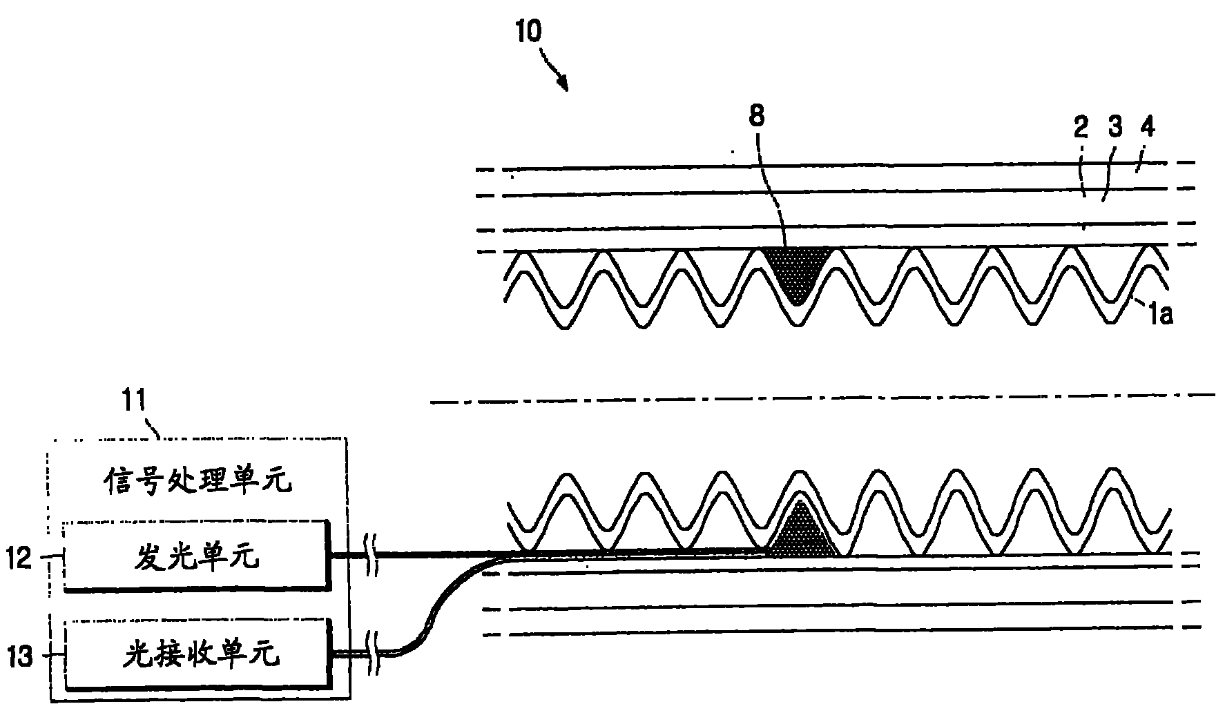
图4示出了根据本发明一个实施例的用于配备有皱褶成形体的超导电力电缆的失导检测系统的结构;FIG. 4 shows the structure of a quench detection system for a superconducting power cable equipped with a corrugated forming body according to an embodiment of the present invention;
图5示出了根据本发明另一实施例的用于配备有导体绞合成形体的超导电力电缆的失导检测系统的结构;FIG. 5 shows the structure of a loss-of-conduction detection system for a superconducting power cable equipped with a conductor strand forming body according to another embodiment of the present invention;
图6是示出超导电力电缆的剖面图,其例示了当在超导屏蔽层中发生失导时在超导电力电缆中的磁场分布;6 is a cross-sectional view showing a superconducting power cable, which illustrates a magnetic field distribution in the superconducting power cable when deconduction occurs in the superconducting shielding layer;
图7示出了根据本发明还一实施例的用于超导电力电缆的导体层或屏蔽层的失导检测系统的结构;以及Fig. 7 shows the structure of a conduction detection system for a conductor layer or a shielding layer of a superconducting power cable according to yet another embodiment of the present invention; and
图8示出了根据本发明再一实施例的用于超导电力电缆的导体层或屏蔽层的失导检测系统的结构。Fig. 8 shows the structure of a loss-of-conduction detection system for a conductor layer or a shielding layer of a superconducting power cable according to yet another embodiment of the present invention.
具体实施方式Detailed ways
以下,参照附图对本发明优选实施例进行详细描述。在进行描述之前,应当明白,在说明书和所附权利要求中使用的术语不应被诠释成局限于通用和字典涵义,而应在允许本发明人为了进行最佳说明而对术语进行适当定义的原则的基础上基于与本发明的技术方面相对应的涵义和概念来加以解释。因此,这里给出的描述只是仅出于例示的目的而给出的优选示例,而不是为了限制本发明的范围,因此应当明白,可以在不脱离本发明的精神和范围的情况下提出本发明的其他等同物和修改例。Hereinafter, preferred embodiments of the present invention will be described in detail with reference to the accompanying drawings. Before proceeding to the description, it should be understood that the terms used in the specification and appended claims should not be construed as limited to the generic and dictionary meanings, but should be used where appropriate to allow the inventors to best describe the terms. On a principle basis, explanations are made based on meanings and concepts corresponding to the technical aspects of the present invention. Accordingly, the description given here is only a preferred example given for the purpose of illustration only, and is not intended to limit the scope of the present invention, so it should be understood that the present invention can be made without departing from the spirit and scope of the present invention. Other equivalents and modifications of .
图2是示出超导电力电缆的剖面图,其例示了在通常状态下超导电力电缆的磁场分布,图3是示出超导电力电缆的剖面图,其例示了当在超导导体层中发生失导时超导电力电缆的磁场分布。参照图2,在构成导体层2的各超导导线中均匀地流有电流的情况下,在导体层2之外形成有具有一定大小的外磁场6b,但是在导体层2内没有形成磁场。然而,如果在电缆的操作过程中超导导线7的一部分失去其超导性并导致失导的发生,则在失导后的超导导线7中流动的电流会减小,而剩余的电流会重新分布以围绕超导导线并在其中流动,因此如图3所示会在导体层内形成磁场6a。由此,可以通过对导体层2中流有的磁场6a的变化进行感测,来检测导体层2的失导。Fig. 2 is a sectional view showing a superconducting power cable, which illustrates the magnetic field distribution of a superconducting power cable in a normal state, and Fig. 3 is a sectional view showing a superconducting power cable, which exemplifies when Magnetic field distribution of a superconducting power cable when deconduction occurs in . Referring to FIG. 2 , when a current uniformly flows through the superconducting wires constituting the
图4示出了根据本发明一个实施例的用于配备有皱褶成形体的超导电力电缆的失导检测系统的结构。参照图4,该系统包括:超导电力电缆10,其配备有用于对导体层2中的磁场6a的变化进行检测的导体层失导检测线圈8;和用于在发生失导时对失导信号进行检测的信号处理单元11。FIG. 4 shows the structure of a quench detection system for a superconducting power cable equipped with a corrugated former according to one embodiment of the present invention. Referring to Fig. 4, the system includes: a
超导电力电缆10包括皱褶成形体1a、包括超导导线并包围皱褶成形体1a的导体层2、包围导体层2的绝缘层3、以及包围绝缘层3的屏蔽层4。超导电力电缆10还包括安装成按环形包围皱褶成形体1a的导体层失导检测线圈8。The
根据本实施例的皱褶成形体1a具有形成在其表面上的多个不规则体。该皱褶成形体1a具有内空部,并且该内空部充当液氮的通道,该液氮将超导导线冷却到临界温度以下,以保持其超导性。The gather forming
导体层失导检测线圈8是设置在皱褶成形体1a与导体层2之间并按环形包围皱褶成形体1a以对超导导体层2的失导进行检测的线圈。在导体层2中发生失导的情况下,导体层失导检测线圈8对磁场的变化进行检测,然后将对应的信号发送给连接到导体层失导检测线圈8的两端的信号处理单元11。此外,导体层失导检测线圈8包括光纤,由此不会导致与导体层2的任何电干扰,从而不会对超导电力电缆10的电力传输造成影响。The conductor layer quench
信号处理单元11安装在超导电力电缆10之外,并对在导体层2中发生失导的情况下在导体层失导检测线圈8处出现的失导信号进行检测。信号处理单元11包括作为诸如激光二极管的光发生元件的发光单元12,和作为诸如光电二极管的光检测元件的光接收单元13。由此,信号处理单元11将在连接到导体层失导检测线圈8的一端的发光单元12中产生的光输入到导体层失导检测线圈8中,并通过连接到导体层失导检测线圈8的另一端的光接收单元13接收从导体层失导检测线圈8发射的光。The
现在,对如上所述地构造的超导电力电缆10的失导检测过程进行如下描述。Now, the process of detecting the loss of conduction of the
通过充当光检测元件的光接收单元13,将在发光单元12中产生并输入给导体层失导检测线圈8的光检测为电信号。如果在导体层2中发生了失导,则经过导体层失导检测线圈8的光会由于磁场的变化而偏振,然后被输出到光接收单元13。The light generated in the
也就是说,根据法拉第的磁光定律,如果将平面偏振光输入到磁场中的透明材料,则透过该透明材料的光具有旋转后的偏振面。由此,由于在没有发生失导的情况下导体层2中的磁场大小变成零,因此透过沿横向缠绕在成形体周围的导体层失导检测线圈8的光的偏振面不会旋转。然而,如果发生了失导,则导体层2内的磁场6a的大小具有大于零的值,因此该光的偏振面会旋转。That is, according to Faraday's magneto-optic law, if plane polarized light is input to a transparent material in a magnetic field, the light passing through the transparent material has a rotated polarization plane. Thereby, since the magnitude of the magnetic field in the
可以将偏振面的旋转角表示成下式:The rotation angle of the polarization plane can be expressed as the following formula:
公式1
θ=kN∮H·d1=kNIθ=kN∮H·d1=kNI
其中:θ为偏振面的旋转角,k为比例系数,N为成形体周围的光纤的横向缠绕数,I为磁场的幅值。Where: θ is the rotation angle of the polarization plane, k is the proportional coefficient, N is the number of transverse windings of the optical fiber around the forming body, and I is the amplitude of the magnetic field.
由此,当磁场大小变大时,此外当在成形体周围的导体层失导检测线圈8的横向缠绕数变大时,偏振面的旋转角增大。将如上所述地偏振的光输出给光接收单元13。根据穿过该偏振面(未示出)的光的强度,在光接收单元13中产生了如下电压,由此使得可以对失导的发生进行检测。Thus, as the magnitude of the magnetic field becomes larger, and also as the number of lateral windings of the conductor layer quench
公式2
VOUT∝VINSIN(2θ)V OUT ∝ V IN SIN(2θ)
其中:VOUT是光接收单元的输出电压,VIN是发光单元的输入电压,θ是偏振面的旋转角。Among them: V OUT is the output voltage of the light receiving unit, V IN is the input voltage of the light emitting unit, θ is the rotation angle of the polarization plane.
为了对失导的发生进行灵敏的检测,优选的是,如在以上公式中说明的那样,增大在成形体周围的导体层失导检测线圈8的横向缠绕数。For sensitive detection of the occurrence of quenching, it is preferable to increase the number of transverse windings of the conductor layer quenching
同时,如图4所示,优选的是,将导体层失导检测线圈8安装成包围形成在皱褶成形体1a的表面上的多个不规则体中的任何一个的凹部,使得不会对超导电力电缆10的外周造成影响。Meanwhile, as shown in FIG. 4 , it is preferable to install the conductor layer quench
图5示出了根据本发明另一实施例的用于配备有导体绞合成形体的超导电力电缆的失导检测系统的结构。参照图5,本实施例的超导电力电缆10使用诸如铜的导体绞合成形体1b,因此与图4的皱褶成形体1a不同,超导电力电缆10的表面是平坦的。由此,如图5所示,优选的是,导体层失导检测线圈8按薄的厚度包围导体绞合成形体1b,以不对超导电力电缆10的外周造成任何影响。FIG. 5 shows the structure of a loss-of-conduction detection system for a superconducting power cable equipped with a conductor strand shaped body according to another embodiment of the present invention. Referring to FIG. 5, the
同时,超导电力电缆10的屏蔽层4可以包括普通导体或超导导线。由此,不仅会在超导屏蔽层中而且会在导体层中发生失导。Meanwhile, the
图6是示出超导电力电缆的剖面图,其例示了当在超导屏蔽层中发生失导时在超导电力电缆中的磁场分布。其中没有发生失导的超导屏蔽层4完全地截断了在导体层2中产生的磁通量,因此在超导屏蔽层4中形成了具有一定大小的磁场,但是在超导屏蔽层4之外没有形成磁场。然而,如果在超导电力电缆10正在进行操作时超导导线14的一部分失去了其超导性并导致失导的产生,则如图6所示磁通量会泄漏到超导屏蔽层4的超导导线14的发生了失导的部分中,因此在超导屏蔽层4之外形成了磁场15。由此,可以通过对超导屏蔽层4的外磁场15的变化进行感测来检测超导屏蔽层4的失导。FIG. 6 is a cross-sectional view showing a superconducting power cable, illustrating a magnetic field distribution in the superconducting power cable when a deconduction occurs in a superconducting shielding layer. The
图7示出了根据本发明还一实施例的用于超导电力电缆的导体层或屏蔽层的失导检测系统的结构。参照图7,该系统包括超导电力电缆10、连接到超导电力电缆10以对导体层2和超导屏蔽层4中的失导进行检测的信号处理单元11。Fig. 7 shows the structure of a loss-of-conduction detection system for a conductor layer or a shielding layer of a superconducting power cable according to yet another embodiment of the present invention. Referring to FIG. 7 , the system includes a
超导电力电缆10包括皱褶成形体1a、超导导体层2、绝缘层3、屏蔽层4以及导体层失导检测线圈8,并且还包括由铜构成并包围超导屏蔽层4的屏蔽层失导检测线圈15。基于配备有皱褶成形体1a的超导电力电缆10例示了图7的实施例,但是也可以使用配备有导体绞合成形体1b的超导电力电缆10。导体层失导检测线圈8和屏蔽层失导检测线圈15的两端都分别连接到发光单元12和光接收单元13,因此信号处理单元11可以对屏蔽层4和导体层2中的失导进行检测。失导检测过程与参照图4说明的失导检测过程相同。The
同时,与导体层失导检测线圈8相类似地,屏蔽层失导检测线圈15可以包括光纤,或者包括诸如铜的导体。由于与对其施加了高电压的超导导体层2不同,将超导屏蔽层4接地,因此尽管将超导屏蔽层4连接到屏蔽层失导检测线圈15,但是不存在电问题。Meanwhile, similarly to the conductor layer
图8示出了根据本发明再一实施例的用于超导电力电缆的导体层或屏蔽层的失导检测系统的结构。参照图8,该系统包括超导电力电缆10、连接到超导电力电缆10以对导体层2中的失导进行检测的信号处理单元11、以及连接到超导电力电缆10以对屏蔽层4中的失导进行检测的电压检测单元16。Fig. 8 shows the structure of a loss-of-conduction detection system for a conductor layer or a shielding layer of a superconducting power cable according to yet another embodiment of the present invention. Referring to Fig. 8, the system includes a
超导电力电缆10包括皱褶成形体1a、超导导体层2、绝缘层3、屏蔽层4以及导体层失导检测线圈8,并且还包括屏蔽层失导检测线圈15,屏蔽层失导检测线圈15包括包围超导屏蔽层4的导体。基于配备有皱褶成形体1a的超导电力电缆10例示了图8的实施例,但是也可以使用具有导体绞合成形体1b的超导电力电缆10。The
如果在屏蔽层4中没有发生失导,即,如果磁通量没有泄漏到屏蔽层4之外,则屏蔽层失导检测线圈15不会感生出电压。然而,在屏蔽层4中发生了失导的情况下,即,如果磁通量泄漏到屏蔽层4之外,则屏蔽层失导检测线圈15会感生出预定电压。由此,连接到屏蔽层失导检测线圈15的两端的电压检测单元16会检测到电压信号,从而使得可以对屏蔽层4中的失导进行检测。电压检测单元16可以采用伏特计或示波器。If no conduction occurs in the
根据本实施例,当在导体层2中发生失导时用于处理光信号的信号处理单元11会检测到失导,并且当在屏蔽层4中发生失导时用于检测电压信号的电压检测单元16会检测到失导。According to the present embodiment, the
已对本发明进行了详细描述,然而,应当明白,仅以例示的方式给出了说明本发明优选实施例的详细说明和具体示例,这是因为,对于本领域的技术人员来说,根据该详细说明,在本发明的精神和范围内的各种变化和修改将变得显见。Having described the present invention in detail, it should be understood that the detailed description and specific examples, illustrating the preferred embodiment of the invention, have been given by way of illustration only because those skilled in the art will, based on the detailed description, Various changes and modifications within the spirit and scope of the invention will become apparent from the description.
工作适用性job suitability
根据本发明,可以在不对超导电力电缆的电力传输造成任何影响的情况下对在超导电力电缆的操作过程中发生的失导实时地进行检测。According to the present invention, it is possible to detect in real time the de-conduction which occurs during the operation of the superconducting power cable without any influence on the power transmission of the superconducting power cable.
Claims (10)
Applications Claiming Priority (2)
| Application Number | Priority Date | Filing Date | Title |
|---|---|---|---|
| KR1020050003423 | 2005-01-13 | ||
| KR1020050003423A KR100622740B1 (en) | 2005-01-13 | 2005-01-13 | Superconducting power cable capable of quench detection and quench detection device using the same |
Publications (2)
| Publication Number | Publication Date |
|---|---|
| CN1961385A true CN1961385A (en) | 2007-05-09 |
| CN100524545C CN100524545C (en) | 2009-08-05 |
Family
ID=36677840
Family Applications (1)
| Application Number | Title | Priority Date | Filing Date |
|---|---|---|---|
| CNB2005800178094A Expired - Fee Related CN100524545C (en) | 2005-01-13 | 2005-06-30 | Superconducting power cable capable of quench detection and quench detection system using the same |
Country Status (6)
| Country | Link |
|---|---|
| US (2) | US7936952B2 (en) |
| EP (1) | EP1836711B1 (en) |
| JP (1) | JP2008527669A (en) |
| KR (1) | KR100622740B1 (en) |
| CN (1) | CN100524545C (en) |
| WO (1) | WO2006075833A1 (en) |
Cited By (5)
| Publication number | Priority date | Publication date | Assignee | Title |
|---|---|---|---|---|
| CN102543296A (en) * | 2012-03-22 | 2012-07-04 | 江苏中煤电缆股份有限公司 | Composite-rubber jacketed flexible cable |
| CN102645572A (en) * | 2012-04-24 | 2012-08-22 | 中国科学院电工研究所 | Voltage drop measuring device for long-distance superconducting power transmission cable |
| CN104157366A (en) * | 2014-07-31 | 2014-11-19 | 上海超导科技股份有限公司 | Superconducting tape with measuring optical fibers sealed inside, and preparation method and device thereof |
| CN110426661A (en) * | 2019-08-13 | 2019-11-08 | 上海交通大学 | Critical current measurnig method, system and the medium of superconductor |
| CN113270224A (en) * | 2021-05-20 | 2021-08-17 | 中国科学院合肥物质科学研究院 | High-voltage-resistant superconducting cable potential detection wire insulation leading-out structure |
Families Citing this family (5)
| Publication number | Priority date | Publication date | Assignee | Title |
|---|---|---|---|---|
| WO2011129245A1 (en) * | 2010-04-12 | 2011-10-20 | 株式会社フジクラ | Superconducting wire material, superconducting coil, and superconducting protective device |
| KR101798659B1 (en) * | 2011-04-27 | 2017-11-16 | 엘에스전선 주식회사 | Super-conducting cable device |
| US9240681B2 (en) | 2012-12-27 | 2016-01-19 | General Electric Company | Superconducting coil system and methods of assembling the same |
| WO2015110148A1 (en) * | 2014-01-21 | 2015-07-30 | Abb Technology Ltd | A power cable assembly device and a power cable provided with such a device |
| GB2588901A (en) * | 2019-11-12 | 2021-05-19 | Tokamak Energy Ltd | Strain-based quench detection |
Family Cites Families (18)
| Publication number | Priority date | Publication date | Assignee | Title |
|---|---|---|---|---|
| US3997235A (en) * | 1975-03-27 | 1976-12-14 | General Electric Company | Shielded power cable separable connector module with snuffer liner having reduced arc-quenching gas generating portion |
| US4140021A (en) * | 1976-10-08 | 1979-02-20 | Agency Of Industrial Science & Technology | Method and device for monitoring superconducting system |
| JPS6433977A (en) * | 1987-07-29 | 1989-02-03 | Fujitsu Ltd | Detecting method for superconducting phase difference |
| JPS6452331A (en) * | 1987-08-21 | 1989-02-28 | Hitachi Cable | Superconductive power cable line |
| US5289128A (en) * | 1992-03-27 | 1994-02-22 | Picker International, Inc. | Superconducting gradient shield coils |
| US5061680A (en) * | 1989-07-31 | 1991-10-29 | Biomagnetic Technologies, Inc. | Superconducting biomagnetometer with remote pickup coil |
| US4989989A (en) * | 1989-08-31 | 1991-02-05 | Westinghouse Electric Corp. | Hydraulic sensor for quench detection and location in superconductors |
| US5289728A (en) * | 1990-11-08 | 1994-03-01 | Jr Johanson, Inc. | Flow-no-flow tester |
| EP0538072A3 (en) * | 1991-10-17 | 1993-08-04 | Canon Kabushiki Kaisha | Method and apparatus for detecting superconductor quench and method and apparatus for preventing superconductor quench |
| JP2886738B2 (en) | 1992-06-26 | 1999-04-26 | キヤノン株式会社 | Superconducting motor, superconducting magnet device and superconducting actuator |
| JPH08122369A (en) * | 1994-10-28 | 1996-05-17 | Sumitomo Electric Ind Ltd | AC current characteristic tester |
| DE69612816T2 (en) * | 1995-11-01 | 2001-12-20 | Kabushiki Kaisha Y.Y.L., Gifu | Superconducting coil |
| US5683179A (en) * | 1995-12-15 | 1997-11-04 | Northrop Grumman Corporation | Apparatus and method for thermoluminescent quench detection for superconducting devices |
| JP3171131B2 (en) | 1997-02-25 | 2001-05-28 | 住友電気工業株式会社 | Method and apparatus for measuring critical current value of superconducting wire |
| JPH11162269A (en) * | 1997-11-27 | 1999-06-18 | Toshiba Corp | Superconducting equipment |
| US6448501B1 (en) * | 1998-03-30 | 2002-09-10 | Mcintyre Peter M. | Armored spring-core superconducting cable and method of construction |
| JP2003500985A (en) * | 1999-05-17 | 2003-01-07 | エヌケイティ リサーチ アクティーゼルスカブ | Overcurrent protection method for superconducting cables. |
| US6864430B2 (en) * | 1999-09-09 | 2005-03-08 | Southwire Company | Superconducting cable having a flexible former |
-
2005
- 2005-01-13 KR KR1020050003423A patent/KR100622740B1/en not_active Expired - Lifetime
- 2005-06-30 WO PCT/KR2005/002085 patent/WO2006075833A1/en not_active Ceased
- 2005-06-30 CN CNB2005800178094A patent/CN100524545C/en not_active Expired - Fee Related
- 2005-06-30 EP EP05780131A patent/EP1836711B1/en not_active Expired - Lifetime
- 2005-06-30 US US11/596,637 patent/US7936952B2/en not_active Expired - Fee Related
- 2005-06-30 JP JP2007551181A patent/JP2008527669A/en active Pending
-
2009
- 2009-07-09 US US12/500,417 patent/US7953304B2/en not_active Expired - Fee Related
Cited By (8)
| Publication number | Priority date | Publication date | Assignee | Title |
|---|---|---|---|---|
| CN102543296A (en) * | 2012-03-22 | 2012-07-04 | 江苏中煤电缆股份有限公司 | Composite-rubber jacketed flexible cable |
| CN102645572A (en) * | 2012-04-24 | 2012-08-22 | 中国科学院电工研究所 | Voltage drop measuring device for long-distance superconducting power transmission cable |
| CN102645572B (en) * | 2012-04-24 | 2014-07-30 | 中国科学院电工研究所 | Voltage drop measuring device for long-distance superconducting power transmission cable |
| CN104157366A (en) * | 2014-07-31 | 2014-11-19 | 上海超导科技股份有限公司 | Superconducting tape with measuring optical fibers sealed inside, and preparation method and device thereof |
| CN104157366B (en) * | 2014-07-31 | 2017-08-08 | 上海超导科技股份有限公司 | Superconducting tape of interior envelope measurement optical fiber and preparation method thereof, device |
| CN110426661A (en) * | 2019-08-13 | 2019-11-08 | 上海交通大学 | Critical current measurnig method, system and the medium of superconductor |
| CN113270224A (en) * | 2021-05-20 | 2021-08-17 | 中国科学院合肥物质科学研究院 | High-voltage-resistant superconducting cable potential detection wire insulation leading-out structure |
| CN113270224B (en) * | 2021-05-20 | 2022-08-16 | 中国科学院合肥物质科学研究院 | High-voltage-resistant superconducting cable potential detection wire insulation leading-out structure |
Also Published As
| Publication number | Publication date |
|---|---|
| EP1836711B1 (en) | 2013-01-02 |
| US20100099572A1 (en) | 2010-04-22 |
| KR20060082711A (en) | 2006-07-19 |
| EP1836711A1 (en) | 2007-09-26 |
| US20080054876A1 (en) | 2008-03-06 |
| US7953304B2 (en) | 2011-05-31 |
| CN100524545C (en) | 2009-08-05 |
| WO2006075833A1 (en) | 2006-07-20 |
| US7936952B2 (en) | 2011-05-03 |
| KR100622740B1 (en) | 2006-09-19 |
| EP1836711A4 (en) | 2012-03-28 |
| JP2008527669A (en) | 2008-07-24 |
Similar Documents
| Publication | Publication Date | Title |
|---|---|---|
| US7953304B2 (en) | Superconducting power cable capable of quench detection and quench detection system using the same | |
| CN107615608B (en) | High-voltage cable accessories and method for producing high-voltage cable accessories | |
| US9349508B2 (en) | Multi-pair differential signal transmission cable | |
| EP3109958A1 (en) | Field control element for a high-voltage cable accessory and method of optically measuring partial discharges | |
| CN1591026A (en) | Temperature stabilized sensing coil and current sensor | |
| FR2864687A1 (en) | CURRENT TRANSFORMERS FOR DETECTING PARTIAL DISCHARGES ON CABLES AND WIRES IN AIRCRAFT | |
| CN100338694C (en) | Superconducting cable | |
| US9588192B2 (en) | Magnetic sensor chip and magnetic sensor | |
| KR102625041B1 (en) | sensor device | |
| CN202549463U (en) | 27.5kV single-phase cable for intelligent electrified railway | |
| CN114113311B (en) | Flexible vortex array sensor for monitoring cracks of porous structure and networking method thereof | |
| US9852831B2 (en) | Superconducting magnet | |
| US20110084716A1 (en) | Diagnostic method for oil-filled electrical device, diagnostic device for implementing the diagnostic method, and oil-filled electrical device provided with the diagnostic device | |
| CN110579680B (en) | A kind of nondestructive testing device and testing method of superconducting cable | |
| JP5229482B2 (en) | Superconducting cable soundness inspection method | |
| CN202403832U (en) | Optical Bragg grating temperature-measurement elastic annular sensor for measuring temperature of porcelain insulator | |
| CN112912742B (en) | Optical detector for high voltage cable accessories and method for optically measuring discharge | |
| JPH04370906A (en) | Method and apparatus for winding of drawn wire | |
| CN219457185U (en) | Power cord, electrical connection device and electrical appliance | |
| KR100738186B1 (en) | Apparatus for detecting quench of shield-layer in superconducting cable core | |
| Bojovschi et al. | Impact of electromagnetic radiation on cascaded failure in high voltage insulators | |
| JPH07159480A (en) | Device for monitoring insulating state of insulated synthetic resin power cable having shielding layer | |
| CN110133811A (en) | A device and method for protecting an optical fiber outlet from an inner-sealed optical fiber superconducting tape | |
| WO2016145579A1 (en) | Cable current sensor and cable having optical sensing unit | |
| WO2024262524A1 (en) | Diamond spin sensor system |
Legal Events
| Date | Code | Title | Description |
|---|---|---|---|
| C06 | Publication | ||
| PB01 | Publication | ||
| C10 | Entry into substantive examination | ||
| SE01 | Entry into force of request for substantive examination | ||
| C14 | Grant of patent or utility model | ||
| GR01 | Patent grant | ||
| CF01 | Termination of patent right due to non-payment of annual fee | ||
| CF01 | Termination of patent right due to non-payment of annual fee |
Granted publication date: 20090805 Termination date: 20180630 |