CN1982182B - Device and method for handling paper trays in an automation unit and automation unit - Google Patents
Device and method for handling paper trays in an automation unit and automation unit Download PDFInfo
- Publication number
- CN1982182B CN1982182B CN2006101690372A CN200610169037A CN1982182B CN 1982182 B CN1982182 B CN 1982182B CN 2006101690372 A CN2006101690372 A CN 2006101690372A CN 200610169037 A CN200610169037 A CN 200610169037A CN 1982182 B CN1982182 B CN 1982182B
- Authority
- CN
- China
- Prior art keywords
- tray
- axis
- paper
- manipulating
- trays
- Prior art date
- Legal status (The legal status is an assumption and is not a legal conclusion. Google has not performed a legal analysis and makes no representation as to the accuracy of the status listed.)
- Expired - Fee Related
Links
Images


Classifications
-
- B—PERFORMING OPERATIONS; TRANSPORTING
- B65—CONVEYING; PACKING; STORING; HANDLING THIN OR FILAMENTARY MATERIAL
- B65H—HANDLING THIN OR FILAMENTARY MATERIAL, e.g. SHEETS, WEBS, CABLES
- B65H19/00—Changing the web roll
- B65H19/10—Changing the web roll in unwinding mechanisms or in connection with unwinding operations
- B65H19/12—Lifting, transporting, or inserting the web roll; Removing empty core
- B65H19/123—Lifting, transporting, or inserting the web roll; Removing empty core with cantilever supporting arrangements
-
- B—PERFORMING OPERATIONS; TRANSPORTING
- B65—CONVEYING; PACKING; STORING; HANDLING THIN OR FILAMENTARY MATERIAL
- B65H—HANDLING THIN OR FILAMENTARY MATERIAL, e.g. SHEETS, WEBS, CABLES
- B65H2301/00—Handling processes for sheets or webs
- B65H2301/40—Type of handling process
- B65H2301/41—Winding, unwinding
- B65H2301/417—Handling or changing web rolls
- B65H2301/4171—Handling web roll
- B65H2301/4173—Handling web roll by central portion, e.g. gripping central portion
-
- B—PERFORMING OPERATIONS; TRANSPORTING
- B65—CONVEYING; PACKING; STORING; HANDLING THIN OR FILAMENTARY MATERIAL
- B65H—HANDLING THIN OR FILAMENTARY MATERIAL, e.g. SHEETS, WEBS, CABLES
- B65H2801/00—Application field
- B65H2801/54—Cigarette making
Landscapes
- Replacing, Conveying, And Pick-Finding For Filamentary Materials (AREA)
- Specific Conveyance Elements (AREA)
- Replacement Of Web Rolls (AREA)
Abstract
本发明涉及一种用于在自动化单元(10,34)中、在至少一个纸盘转换装置(12)和至少一个用于存储若干纸盘(11)的装载区域(13)之间操纵纸盘(11)的装置(16),其包括带操纵元件(25)的操纵机构(24),所述纸盘(11)设置在所述操纵元件(25)上,所述操纵元件(25)可沿着若干轴线移动,以便在所述自动化单元(10,34)中接受、传送和卸载所述纸盘(11),其特征在于,至少一个所述轴线,即垂直轴线(Z轴)在Z方向上是不可移动的,所述操纵元件(25)设置在可沿着所述垂直轴线(Z轴)移动的支架(30,36)上,以便在所述Z方向上垂直运动。此外,本发明还涉及一种带有这种装置(16)的自动化单元(10,34)以及相应的方法。
The invention relates to a method for handling paper trays in an automated unit (10, 34) between at least one tray changing device (12) and at least one loading area (13) for storing several paper trays (11) (11) The device (16), which comprises a manipulation mechanism (24) with a manipulation element (25), the paper tray (11) is arranged on the manipulation element (25), and the manipulation element (25) can moves along several axes for receiving, conveying and unloading said trays (11) in said automation unit (10, 34), characterized in that at least one of said axes, namely the vertical axis (Z-axis) is in the Z Directly immovable, said manipulating element (25) is arranged on a support (30, 36) movable along said vertical axis (Z-axis) for vertical movement in said Z-direction. Furthermore, the invention relates to an automation unit (10, 34) with such a device (16) and a corresponding method.
Description
技术领域technical field
本发明涉及一种用于在自动化单元中,在至少一个纸盘(bobbin)转换装置和至少一个存储若干纸盘的装载区域之间操纵纸盘的装置,其包括带有用于操纵设置于其上的纸盘的操纵元件的操纵机构,操纵元件沿着若干轴线移动,以便在自动化单元中接受、传送和卸载纸盘。The invention relates to a device for manipulating bobbins in an automated unit between at least one bobbin changing device and at least one loading area for storing several bobbins, comprising The handling mechanism of the handling element of the paper tray, which moves along several axes to accept, transfer and unload the paper tray in the automation unit.
此外,本发明还涉及一种用于在自动化单元中,在至少一个纸盘转换装置和至少一个储存若干纸盘的装载区域之间操纵纸盘的方法,其包括如下步骤:a)通过纸盘转换装置开始纸盘转换,b)起动用于操纵纸盘的自动化装置,c)从装载区域拿取纸盘,d)将纸盘传送到纸盘转换装置,e)将纸盘卸载到纸盘转换装置,其中,步骤c)至e)是通过可沿着若干轴线移动的操纵机构或所述装置的操纵元件来执行的,操纵元件用于操纵设置在其上面的纸盘。Furthermore, the invention relates to a method for manipulating paper trays in an automated cell between at least one tray changing device and at least one loading area storing several paper trays, comprising the steps of: a) passing the tray The changer starts the tray changeover, b) activates the automation for manipulating the tray, c) picks up the tray from the loading area, d) transfers the tray to the tray changer, e) unloads the tray into the tray Switching device, wherein steps c) to e) are carried out by means of a manipulating mechanism movable along several axes or a manipulating element of said device for manipulating a paper tray arranged thereon.
本发明还涉及一种用于自动化地操纵纸盘的自动化单元,其包括至少一个纸盘转换装置、至少一个用于存储若干纸盘的装载区域和至少一个用于操纵纸盘的装置。The invention also relates to an automation unit for automated handling of paper trays, comprising at least one tray changing device, at least one loading area for storing several paper trays and at least one device for handling paper trays.
背景技术Background technique
这种自动化单元尤其用于烟草加工工业。在这种情况下,自动化单元可用于制备各种材料。这些材料例如为香烟纸、水松纸以及其它可卷绕的材料,其卷绕在辊轴上,在这种情况下,可连续地处理这些所谓的纸盘。为了容许尽可能连续地处理这些纸盘,可将完整纸盘传送到纸盘转换装置上。在这个纸盘转换装置上,将完整纸盘展开以进行处理。一旦纸盘几乎用完,为纸盘转换装置供给另一完整纸盘,其卷筒纸连接在未卷绕纸盘的卷筒纸上。在这一拼接操作结束时,拿取残余材料。Such automated units are used in particular in the tobacco processing industry. In this case, automated cells are available for the preparation of various materials. These materials are, for example, cigarette paper, tipping paper and other rollable materials, which are wound on rolls, in which case these so-called paper discs can be processed continuously. In order to allow as continuous processing of these trays as possible, complete trays can be transferred to a tray changer. On this tray converter, complete trays are unfolded for processing. Once the tray is nearly empty, the tray changer is fed another full tray with its web attached to the web of the unwound tray. At the end of this splicing operation, remove the remaining material.
纸盘在自动化单元中的操纵通过用于操纵纸盘的装置来执行。带有操纵纸盘的装置的自动化单元是已知的,其中,起重架横跨在纸盘转换装置上。起重架还横跨其中完整纸盘存储在平板架上的装载区域。起重架自动机械接受来自装载区域的纸盘,将其传送至纸盘转换装置,并将其卸载到纸盘转换装置上。在这个过程中,起重架自动机械在三个方向上移动。起重架或设置在起重架上的操纵元件包括三条可自由移动的运动轴线,这包括水平面上的X方向和Y方向,以及垂直平面上的Z方向。例如在DE 4018266 A1可找到这种装置。那里所述的装置包括一种起重架,其包括三条可自由移动的轴线。在这里,操纵元件刚性地连接在这些轴线上。这意味着,例如操纵元件在Z方向上的运动可导致Z轴线在上边位置向上移动而离开起重架。这具有尤其在垂直方向上需要较大空间的缺陷,这就极大地限制了这种操纵装置的应用领域。The handling of the paper trays in the automation unit is performed by means for handling the paper trays. Automated cells with means for handling trays are known, in which a lifting frame straddles the tray changeover. The lift frame also spans the load area where complete trays are stored on pallets. The crane robot accepts trays from the load area, transfers them to the tray changer, and unloads them onto the tray changer. During this process, the crane robot moves in three directions. The gantry or the operating element arranged on the gantry comprises three freely movable axes of movement, which include the X and Y directions in the horizontal plane, and the Z direction in the vertical plane. Such a device can be found, for example, in DE 4018266 A1. The device described there comprises a mast comprising three freely movable axes. Here, the actuating element is rigidly connected on these axes. This means that, for example, a movement of the actuating element in the Z direction can cause the Z axis to move upwards away from the lifting frame in the upper position. This has the disadvantage of requiring relatively large space, especially in the vertical direction, which greatly limits the field of application of such actuating devices.
发明内容Contents of the invention
因此,本发明的目的是提供一种紧凑且可靠的用于操纵纸盘的装置。另外,本发明的目的还包括提出一种相应的方法。本发明的另一目的包括,提供一种紧凑且可靠的自动化单元。It is therefore an object of the present invention to provide a compact and reliable device for handling paper trays. In addition, the object of the present invention also includes proposing a corresponding method. Another object of the invention consists in providing a compact and reliable automation unit.
这个目的通过具有上述特征的装置来实现,即至少一条轴线、例如垂直轴线(Z轴)设计成在Z方向上不能移动,而操纵元件设置在可沿着垂直轴线(Z轴)移动的支架上,以便在Z方向上进行垂直运动。这就确保了用于操纵纸盘的装置总是保持在自动化单元中,而不管其移动的距离如何。换句话说,可以到达自动化单元中所有必要的位置,而无须操作机构在Z方向上向上延伸而离开自动化单元。这就允许在低矮或狭窄的生产设施内使用该装置。This object is achieved by a device having the above-mentioned features, that is, at least one axis, for example a vertical axis (Z-axis), is designed immovable in the Z-direction, and the operating element is arranged on a support movable along the vertical axis (Z-axis) , for vertical movement in the Z direction. This ensures that the means for manipulating the trays always remains in the automated cell, regardless of the distance it has moved. In other words, all necessary positions in the automation cell can be reached without the operating mechanism extending upwards in the Z direction away from the automation cell. This allows the unit to be used in low or narrow production facilities.
在本发明的第一优选实施例中,操纵装置被设计成一种起重架自动机械。起重架自动机械是一种特别简单且稳定、并因而可靠的结构,其容许紧凑的设计。In a first preferred embodiment of the invention, the handling device is designed as a crane robot. The crane robot is a particularly simple and stable and thus reliable construction which allows a compact design.
在本发明的另一优选实施例中,操作机构被设计成一种旋转臂自动机械。这个实施例在操作上是比较灵活且安全的,并且以特别可靠的方式容许在自动化单元中利用若干纸盘转换装置来操纵纸盘。In a further preferred embodiment of the invention, the operating mechanism is designed as a rotary arm robot. This embodiment is relatively flexible and safe in operation and allows, in a particularly reliable manner, the handling of the trays in an automated cell with several tray changing devices.
这个目的通过具有上述步骤的方法来实现,即,通过可在Z轴上沿Z方向移动的支架,来实现操纵元件沿着垂直轴线(Z轴)的运动。This object is achieved by a method with the steps described above, ie the movement of the actuating element along a vertical axis (Z-axis) by means of a carriage movable on the Z-axis in the Z-direction.
该目的还通过一种具有上述特征的自动化单元来实现,并根据这样的事实,即,用于操纵纸盘的装置是根据权利要求1至18中任一项进行设计的。This object is also achieved by an automation unit having the above-mentioned characteristics and by virtue of the fact that the device for handling the paper tray is designed according to any one of claims 1 to 18 .
根据本公开的第一方面,提供了一种用于在自动化单元中、在至少一个纸盘转换装置和至少一个用于存储若干纸盘的装载区域之间操纵纸盘的装置,其包括带有用于设置在其上的纸盘的操纵元件的操纵机构,所述操纵元件可沿着若干轴线移动,以便在所述自动化单元中接受、传送和卸载所述纸盘,其特征在于,所述轴线中的至少一条、即垂直的Z轴在Z方向上是不可移动的,所述操纵元件设置在可沿着所述垂直的Z轴移动的支架上,以便在所述Z方向上垂直运动,其中,所述操纵机构被设计成可操纵用于若干纸盘转换装置的纸盘,所述若干纸盘转换装置各具有其自身的装载区域。According to a first aspect of the present disclosure there is provided a device for handling trays in an automated unit between at least one tray changing device and at least one loading area for storing several trays, comprising a Manipulating mechanism for handling elements of paper trays arranged thereon, said handling elements being movable along several axes in order to receive, transfer and unload said paper trays in said automation unit, characterized in that said axes At least one of them, that is, the vertical Z axis is not movable in the Z direction, and the manipulation element is arranged on a support movable along the vertical Z axis so as to move vertically in the Z direction, wherein , the handling mechanism is designed to handle trays for several tray changing devices each having its own loading area.
根据本公开的第二方面,提供了一种用于自动化地操纵纸盘的自动化单元,包括至少一个纸盘转换装置、至少一个用于存储若干纸盘的装载区域以及至少一个用于操纵所述纸盘的装置,其特征在于,所述用于操纵纸盘的装置是根据本公开的第一方面来设计的。According to a second aspect of the present disclosure, there is provided an automation unit for automated handling of paper trays, comprising at least one tray changer, at least one loading area for storing several paper trays and at least one for handling the A device for a paper tray, characterized in that the device for manipulating the paper tray is designed according to the first aspect of the present disclosure.
根据本公开的第三方面,提供了一种用于在自动化单元中、在至少一个纸盘转换装置和至少一个用于储存若干纸盘的装载区域之间操纵纸盘的方法,包括以下步骤:According to a third aspect of the present disclosure there is provided a method for handling trays in an automated cell between at least one tray changing device and at least one loading area for storing several trays, comprising the steps of:
a)通过纸盘转换装置开始纸盘转换,a) Tray switching is started by the tray switching device,
b)起动用于操纵所述纸盘的自动化装置,b) activating an automation device for manipulating said tray,
c)从所述装载区域拿取纸盘,c) take the tray from said loading area,
d)将所述纸盘传送到所述纸盘转换装置上,d) conveying said tray to said tray changer,
e)将所述纸盘卸载到所述纸盘转换装置上,e) unloading said tray onto said tray changer,
步骤c)至e)是通过可沿着若干轴线移动的操纵机构、或者通过用于操纵设置于其上的纸盘的装置的操纵元件来执行的,steps c) to e) are carried out by a manipulating mechanism movable along several axes, or by a manipulating element of a device for manipulating a paper tray arranged thereon,
其特征在于,所述操纵元件沿着垂直的Z轴的运动是通过可在Z轴上沿着Z方向移动的支架来执行的,It is characterized in that the movement of the operating element along the vertical Z-axis is carried out by means of a carriage movable along the Z-axis along the Z-direction,
其中,所述操纵机构操纵用于若干纸盘转换装置的纸盘,所述若干纸盘转换装置各具有其自身的装载区域。Therein, the steering mechanism handles trays for several tray changing devices, each of which has its own loading area.
上面已经描述了由本发明的方法和本发明的自动化单元所产生的优势,因此在这里不再进行重复。The advantages resulting from the method of the invention and the automation unit of the invention have already been described above and will therefore not be repeated here.
附图说明Description of drawings
从从属权利要求和细节描述中,将清楚其它有利的或优选的特征和实施例。以下将借助于附图更详细地描述特别优选的实施例和方法。这些附图显示了:Other advantageous or preferred features and embodiments will be apparent from the dependent claims and the detailed description. Particularly preferred embodiments and methods will be described in more detail below with the aid of the figures. These drawings show:
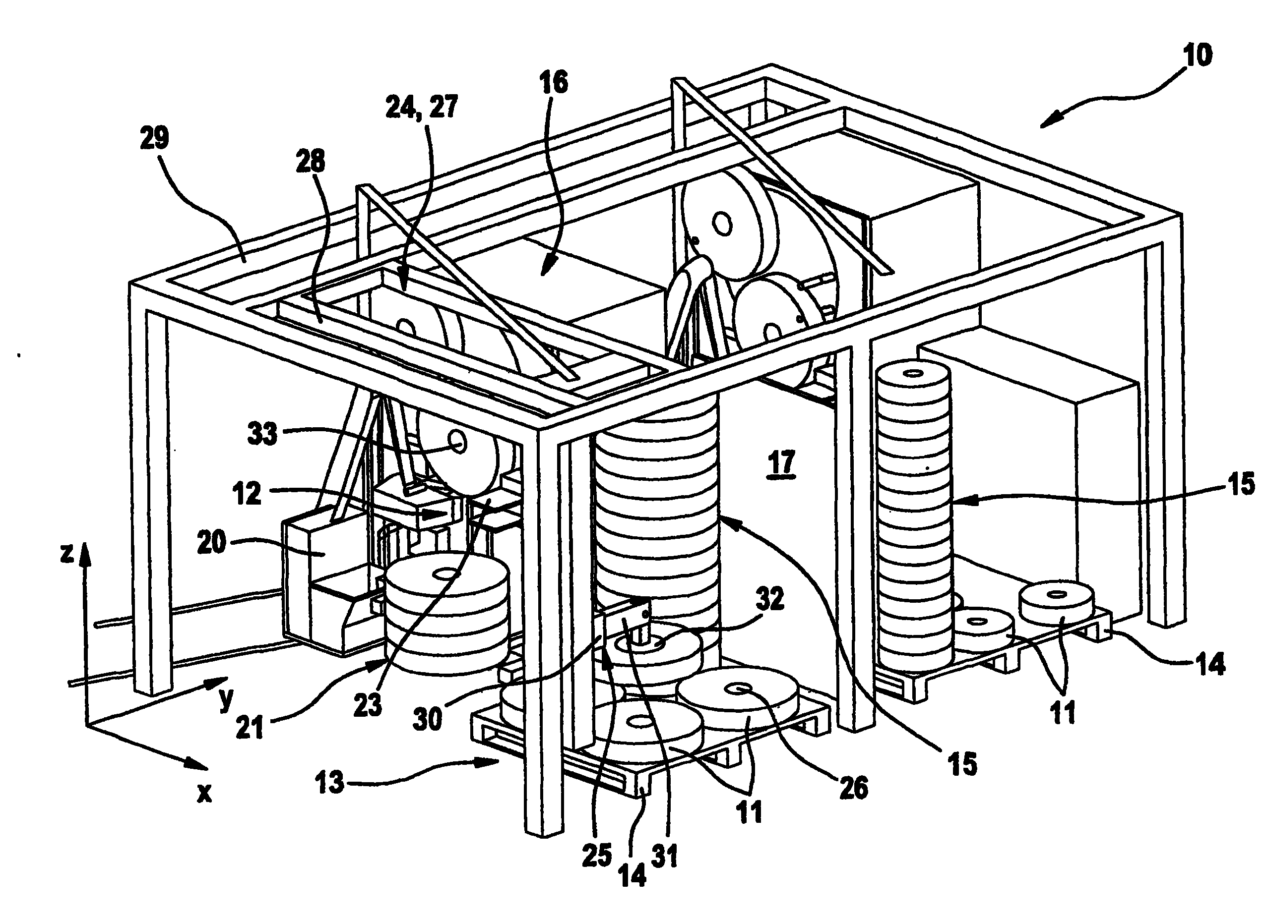
图1是带有两个纸盘转换装置和相关装载区域以及操纵机构的自动化单元的透视图,所述操纵机构被设计成起重架自动机械,Figure 1 is a perspective view of an automation unit with two tray changers and associated loading areas and a handling mechanism designed as a crane robot,
图2是图1中的自动化单元的侧视图,Figure 2 is a side view of the automation unit in Figure 1,
图3是图1中的自动化单元的后视图,Figure 3 is a rear view of the automation unit in Figure 1,
图4是图1中的自动化单元的顶视图,和Figure 4 is a top view of the automation unit in Figure 1, and
图5是带有两个纸盘转换装置和相关装载区域以及操纵机构的自动化单元的透视图,所述操纵机构被设计成旋转自动机械。Figure 5 is a perspective view of an automation unit with two tray changers and associated loading areas and a handling mechanism designed as a rotary robot.
具体实施方式Detailed ways
下面所示和所述的装置用于在自动化单元中的一个或多个纸盘转换装置处改变纸盘,这些自动化单元优选在用于烟草加工工业的产品制造生产线中使用。The device shown and described below is used to change paper trays at one or more tray changing devices in automated units preferably used in product manufacturing lines for the tobacco processing industry.
图1至图4中所示的自动化单元10被设计成用于操纵纸盘11。自动化单元10包括至少一个纸盘转换装置12,在所述实施例中为两个纸盘转换装置12,其带有相应的相关的装载区域13。用于各纸盘转换装置12的装载区域13是一种单独的用于多个纸盘11的储器,这些纸盘优选以叠组15的形式设置在平板架14上。在所述实施例中,各装载区域13被设计成可接受平板架14。然而,装载区域13当然还可具有其它的尺寸,并被设计成可接受一个以上的平板架14。此外,装置16形成了自动化单元10的一部分,所述装置16用于操纵纸盘11,或者更精确地说,尤其是用于从平板架14中接受纸盘11,并用于将纸盘11从装载区域13传送到纸盘转换装置12上,以及用于将纸盘11卸载到纸盘转换装置12上。The
彼此相邻地定位的自动化单元10的装载区域13在空间上是彼此分开的。这种分开是通过例如分区17等而形成的。通过门18等可到达各装载区域13。这些通常设计成为自动门的入口机构可通过自动导向车、操作员等进行促动。操作员经由门19可到达纸盘转换装置12的工作区域。在门19的区域设置了用于收集纸盘11转换期间所产生的残余物(例如纸盘芯、材料残余物等)的收集容器20。The loading areas 13 of
在各纸盘转换装置12的区域中设置或形成了用于纸盘的额外储器21。储器21独立于实际装载区域13之外而定位,并且定位在其外部。这个储器21用于确保在平板架于装载区域13内的转换期间为转换装置12供给纸盘。这两个区域,即纸盘转换装置12的工作区域和装载区域13通过挡光板22而分开。后者首先和主要用于检测操作员是否已经从纸盘转换装置12的工作区域移动到装载区域13中。An
可选的是,纸盘翻转器23可与一个或每一个纸盘转换装置12相关联。这个纸盘翻转器23设计成可将不正确放置的纸盘11、例如开口方向不正确的纸盘11翻转180°,然后使其定位在正确位置。Optionally, a tray inverter 23 may be associated with one or each
在该优选实施例中,自动化单元10包括测量元件,其用于检测相应装载区域13中的叠组15的高度。利用这种测量元件,可确定平板架14上单个叠组的高度,并用于控制操纵纸盘11的装置10。这种控制还可用于提供一方面用于操纵纸盘11的装置16与另一方面的入口机构、即门18和门19之间的功能连接,这样,当其中一个入口机构打开时,出于安全性考虑可关闭装置16。In this preferred embodiment, the
下面将针对上述自动化单元10,来描述用于操纵纸盘11的装置16。装置16包括上面设有操纵元件25的操纵机构24。为了能够执行接受、传送和卸载所需和/或所必要的运动,操纵机构24或操纵元件25可在自动化单元10中沿着若干轴线移动。如从图中可以看出,在自动化单元10中用于操纵纸盘11的装置14可设计成具有两个纸盘转换装置12和两个装载区域13。这个实施例只是一个示例,并不排除在自动化单元10中利用一个或两个以上纸盘转换装置12来操纵纸盘11。The means 16 for handling the paper tray 11 will be described below with respect to the
操纵元件25被设计成一种纸盘抓具机构。纸盘抓具机构尤其用于接受、固定、传送和卸载纸盘11,并被设计成用于接受纸盘芯26中的纸盘11。优选与纸盘抓具机构相关联的是抓取圆筒,纸盘部分通过该抓取圆筒可在抓具中径向地滑动。抓取圆筒优选连接在装置16或自动化单元10的公用控制器上。此外,和抓具机构相关联的是至少一个用于检测纸盘11位置的元件。这个元件例如可以是激光传感器,通过该激光传感器可找到纸盘11或纸盘芯26的中心。The actuating element 25 is designed as a tray gripper mechanism. The tray gripper mechanism is used, inter alia, to receive, secure, transport and unload trays 11 and is designed to accept trays 11 in a tray core 26 . Preferably associated with the tray gripper mechanism is a gripper cylinder by which the tray portion can slide radially in the gripper. The gripping cylinders are preferably connected to a common controller of the
操作机构24可被设计在不同的实施例中。在第一实施例中,操作机构24被设计成一种起重架自动机械27。起重架自动机械27包括起重架28,其具有两条移动轴线,即X轴和Y轴。起重架27可在水平方向上在引导件上沿着X方向和Y方向而移动,引导件设置在纸盘转换装置12的上面,并形成框架29的一部分。因此起重架28可沿着引导件而在两个彼此成直角的方向上进行直线运动。起重架27具有另一垂直轴线,即Z轴。这个Z轴可在X方向和Y方向上移动,但是Z轴相对于Z方向是不可移动的。这意味着,Z轴在任何时候或任何位置都不会向上突出到起重架自动机械27之外,更精确地说,不会突出到框架29之外。操纵元件25和Z轴相关联。The operating mechanism 24 can be designed in different embodiments. In a first embodiment, the operating mechanism 24 is designed as a crane robot 27 . The gantry robot 27 includes a
对于操纵元件25的上下运动,提供了可沿着Z轴在Z方向上移动的支架30。在这个支架30上设有传送臂31。在传送臂31的自由端,操纵元件25设置成可绕枢轴旋转。这种包括传送臂31和设置成可在传送臂上绕枢轴旋转的操纵元件25在内的机构,被称为纸盘旋转器,它可使定位在水平位置的纸盘11在装载区域13中旋转90°而进入垂直位置,以便将纸盘11卸载到纸盘转换装置12上。这种旋转机构可通过气动或某些其它已知的方式来促动。为了将纸盘11卸载到纸盘转换装置12上,与操纵元件25相关联的元件32优选也是气动操作的,以用于使纸盘11离开操纵元件25而滑动到水平定向的纸盘转换装置12的支撑轴33上。For the up and down movement of the actuating element 25 , a
所有的轴线,即X轴、Y轴和Z轴,或者相应轴线方向上的运动,都可彼此独立地进行控制,从而确保针对所需目的而在自动化单元10中操纵纸盘11。All axes, ie X, Y and Z, or movements in the directions of the respective axes, can be controlled independently of each other to ensure that the tray 11 is manipulated in the
图5中所示的实施例具有基本上可与图1至4所示实施例相当的结构,使得针对自动化单元10的详细描述也同等地适用于图5的自动化单元34。因此相应的标号也用于相同的部件。同图1实施例对比而言,对于图5中所示的自动化单元34,操作机构24被设计成一种旋转臂自动机械35。The embodiment shown in FIG. 5 has a substantially comparable structure to the embodiment shown in FIGS. 1 to 4 , so that the detailed description for the
旋转臂自动机械35也具有垂直轴线,即Z轴。Z轴在Z方向上是不可移动的。这意味着Z轴在任何时候或任何位置都不会向上突出到自动化单元34之外。Z轴设置成固定的,使得Z轴在直线的且水平的X方向和直线的且水平的Y方向上都不能移动。操纵元件25和Z轴相关联。The rotating arm robot 35 also has a vertical axis, the Z axis. The Z axis is not movable in the Z direction. This means that the Z-axis does not protrude upwards beyond the automation unit 34 at any time or in any position. The Z-axis is fixed so that the Z-axis cannot move in both the linear and horizontal X direction and the linear and horizontal Y direction. The operating element 25 is associated with the Z axis.
更精确地说,与Z轴相关联的是可沿着Z轴在Z方向上移动的支架36。在这个支架36上设有旋转臂37。这个旋转臂37可绕垂直定向的轴线、即轴而旋转。在所示实施例中,轴和Z轴是等同的。换句话说,旋转臂37可绕Z轴旋转。然而,轴也可偏离Z轴。More precisely, associated with the Z-axis is a carriage 36 movable in the Z-direction along the Z-axis. A swivel arm 37 is provided on this support 36 . This swivel arm 37 can rotate around a vertically oriented axis, i.e. axis to rotate. In the illustrated embodiment, Axis and Z-axis are equivalent. In other words, the rotating arm 37 is rotatable around the Z axis. However, The axis can also be offset from the Z axis.
旋转臂37是径向地定向的,并且限定了水平延伸的R轴。R轴定向成在R方向上是不可移动的,并且具有支架38,其部分可沿着旋转臂37而在径向R方向上移动。在这个支架38上设有操纵元件25,该操纵元件25根据关于第一实施例所述的方式设计而成。利用支架38,操纵元件25可在R方向上移动。The swivel arm 37 is radially oriented and defines an R-axis extending horizontally. The R axis is oriented so as to be immovable in the R direction, and has a bracket 38 partly movable in the radial R direction along the rotating arm 37 . Arranged on this support 38 is an actuating element 25 which is designed in the manner described with respect to the first exemplary embodiment. With the bracket 38 the actuating element 25 is movable in the R direction.
在使用上述实施例的起重架自动机械27的情况下,纸盘转换装置12包括支撑轴33,其是水平定向的,使得可在垂直位置将纸盘11传送到纸盘转换装置12上。在使用上述实施例的旋转臂自动机械35的情况下,夹圈39与纸盘转换装置12相关联。夹圈39用于接受纸盘11,并且一方面可旋转180°,使得错误定位的纸盘11可移动到正确位置,而另一方面可旋转90°,使得纸盘11可在被水平放下之后移动到垂直位置。为了固定纸盘11,夹圈39包括例如可气动操作的夹紧元件40。利用这些夹紧元件40,可从外部在其圆周面处夹紧纸盘11。In the case of using the crane robot 27 of the above-described embodiment, the
以下将更详细地描述用于所示两个实施例的方法的原理。The principles of the method for the two illustrated embodiments will be described in more detail below.
在操纵机构24设计成起重架自动机械27的情况下,起重架28最初处于待命位置。一旦纸盘转换装置12开始纸盘11的转换,起重架28就离开待命位置。沿着X轴和Y轴在水平方向上进行用于操纵纸盘11的起重架28的运动。在垂直方向上沿着在Z方向上不可移动的Z轴而进行支架30的运动。起重架28和操纵元件25移动到装载区域13,以接受来自平板架14的完整纸盘11。在这个过程中,接近纸盘叠组,以便从中拿取最后的纸盘11。如果接近的堆叠位置是空的,那么操纵机构24移动到下一个叠组15。作为备选,可交替地处理一排叠组15。当前面的堆叠位置为空时,就接近平板架14上的下一排叠组。当已经从平板架14上拿取最后的纸盘11时,可请求新的平板架14。如果平板架14上没有纸盘11,那么就接近储器21。为了从平板架14或储器21中拿取纸盘11,需要接近纸盘11,并确定其中心。这可通过用于检测位置的合适元件以通常的方式来实现。一旦已经确定接受位置,那么纸盘抓具机构就进入纸盘芯26中。通过控制抓取圆筒,使抓具中的部件径向地移动,从而夹紧纸盘芯26。在这个过程中,可调整所述部分以适合纸盘11的不同芯直径。然后将现在连接在操纵元件25上的纸盘11传送到纸盘转换装置12上。In the case of the operating mechanism 24 configured as a crane robot 27 , the
在纸盘11具有错误位置(例如具有错误的开口位置)的情况下,首先将其传送到纸盘翻转器23上,并由后者翻转180°。用于该用途的纸盘翻转器在其圆周面上保持住纸盘11,之后使纸盘11翻转。接下来,操纵机构24移回到纸盘翻转器,并再次拿取纸盘11。现在已正确定向的纸盘11将被传送到纸盘转换装置12上。在纸盘转换装置12的转盘到达接受位置之前,操纵机构24等待垂直定向的纸盘11旋转90°。当转盘已经达到正确的放置位置,元件32使纸盘滑动,而使其滑动到支撑轴33上。然后起重架28移动到待命位置。In the event that a paper tray 11 has a wrong position (for example with a wrong opening position), it is first conveyed to the paper tray inverter 23 and turned by the latter through 180°. The paper tray inverter used for this purpose holds the paper tray 11 on its peripheral surface and then turns the paper tray 11 over. Next, the handling mechanism 24 moves back to the tray turner, and picks up the tray 11 again. The tray 11 , now correctly oriented, will be transferred to the
利用旋转的自动机械35作为操纵机构24的方法,其原理基本上对应于刚才所述的原理。然而,旋转臂自动机械34的运动是在水平面中进行的,即绕
如果纸盘转换装置12再次请求新的纸盘11,那么可重复上述操作。如果将要夹紧纸盘11的平板架14是空的,那么操纵机构24将从储器21中取得纸盘11。If the paper
如果必须更换平板架14,那么操纵机构24就移动到待命位置。只有那时,通向装载区域13的入口机构(门18)将会自动打开。空的平板架14被去除,并将新的满载平板架14定位。通过例如由操作员自己手动或由自动车自动给出的确认信号,可再次关闭门18。之后,操纵机构24开始接近新的平板架14,并填充储器21。然而,纸盘转换装置12的装载具有优于填充储器21的优先权。If the
出于安全性考虑,一旦入口机构、即门18和/或门19打开,就断开操纵机构24和操纵元件25。在这过程中,纸盘转换功能也停止了,而纸盘转换装置12的正常解绕展开工作仍然继续。For safety reasons, the actuating mechanism 24 and the actuating element 25 are disconnected as soon as the access mechanism, ie the door 18 and/or the door 19 is opened. During this process, the paper tray switching function is also stopped, while the normal unwinding and unfolding work of the paper
在自动化单元10,34起动之后,必须测量平板架14上和储器21中的叠组15的高度。在入口机构已经打开的情况下,也要进行相同的工作。然而,在后一情况下,只是在操作员已经进入装载区域13,并因此触发了挡光板22时,才需要进行测量。如果使用起重架自动机械27,那么由于固定Z轴的原因,应首先测量从Y方向上看去的前面叠组15,之后对其进行处理。只有在处理完前面的叠组15之后,才能测量Y方向上的后一叠组15。进行测量和处理也可在渐进的X方向上进行测量和处理。如果使用旋转臂自动机械35,就可使支架36沿着Z轴移动到其上方位置。然后使支架38沿着R轴移动。只有那时,旋转臂37可绕
Claims (33)

Applications Claiming Priority (2)
| Application Number | Priority Date | Filing Date | Title |
|---|---|---|---|
| DE102005060638A DE102005060638A1 (en) | 2005-12-13 | 2005-12-13 | Bobbins handling device, has mechanism with bobbin handling unit that is arranged in such a manner that it is vertically movable in Z-direction to slides, which are movable along vertical axis |
| DE102005060638.5 | 2005-12-13 |
Publications (2)
| Publication Number | Publication Date |
|---|---|
| CN1982182A CN1982182A (en) | 2007-06-20 |
| CN1982182B true CN1982182B (en) | 2010-06-09 |
Family
ID=37845138
Family Applications (1)
| Application Number | Title | Priority Date | Filing Date |
|---|---|---|---|
| CN2006101690372A Expired - Fee Related CN1982182B (en) | 2005-12-13 | 2006-12-12 | Device and method for handling paper trays in an automation unit and automation unit |
Country Status (5)
| Country | Link |
|---|---|
| EP (1) | EP1798174B1 (en) |
| JP (1) | JP2007161488A (en) |
| CN (1) | CN1982182B (en) |
| DE (1) | DE102005060638A1 (en) |
| PL (1) | PL1798174T3 (en) |
Cited By (3)
| Publication number | Priority date | Publication date | Assignee | Title |
|---|---|---|---|---|
| CN106660735A (en) * | 2014-08-28 | 2017-05-10 | 宝洁公司 | Robot Unwinder |
| CN109562899A (en) * | 2016-06-22 | 2019-04-02 | 株式会社瑞光 | Sheet supply system and sheet supply method |
| CN109641709A (en) * | 2016-06-22 | 2019-04-16 | 株式会社瑞光 | Roller conveying device and roller conveying method |
Families Citing this family (8)
| Publication number | Priority date | Publication date | Assignee | Title |
|---|---|---|---|---|
| CN103879813B (en) * | 2014-03-22 | 2017-07-07 | 昆明鼎承科技有限公司 | Paper disc automatic supply device |
| CN106364957B (en) * | 2015-07-21 | 2018-11-02 | 中烟机械技术中心有限责任公司 | Device for supplying two kinds of paper discs |
| DE102017206549A1 (en) * | 2017-04-19 | 2018-10-25 | Robert Bosch Gmbh | Consumables handling device for transporting and / or handling at least one consumable material, in particular a packaging material |
| CN107310959B (en) * | 2017-07-25 | 2019-09-13 | 合肥国轩高科动力能源有限公司 | Automatic roll changing device |
| CN107932497B (en) * | 2017-11-14 | 2020-12-04 | 南通大学 | An inner centering structure paper tray picking and placing manipulator and its control system and control method |
| IT202000030662A1 (en) * | 2020-12-14 | 2022-06-14 | Futura Spa | PLANT AND PROCESS FOR THE HANDLING OF CARDBOARD ROLLS. |
| PL444502A1 (en) * | 2023-04-20 | 2024-10-21 | International Tobacco Machinery Poland Spółka Z Ograniczoną Odpowiedzialnością | A system for loading the bobbin onto the unwinding device, a manipulator head for the bobbin loading system and a method for loading the bobbin |
| PL446553A1 (en) * | 2023-10-30 | 2025-05-05 | International Tobacco Machinery Poland Spółka Z Ograniczoną Odpowiedzialnością | Material strand feeding system, manipulator head for strand feeding system and strand feeding method |
Citations (6)
| Publication number | Priority date | Publication date | Assignee | Title |
|---|---|---|---|---|
| US5269479A (en) * | 1991-04-16 | 1993-12-14 | Fabriques De Tabac Reunies, S.A. | Reel-transfer apparatus and method |
| EP0649806A1 (en) * | 1993-10-20 | 1995-04-26 | Eastman Kodak Company | Apparatus and method for loading rolls of web into a chamber |
| EP0664268A2 (en) * | 1994-01-20 | 1995-07-26 | G.D Societa' Per Azioni | Device for feeding reels to a user machine |
| EP0936172A2 (en) * | 1998-02-17 | 1999-08-18 | Focke & Co. (GmbH & Co.) | Device for handling packages |
| CN1371844A (en) * | 2001-02-27 | 2002-10-02 | 福克有限公司 | System for supplying package material to package machine |
| CN1406819A (en) * | 2001-05-11 | 2003-04-02 | 吉第公司 | Method and apparatus for feeding packing materials to operating mechanism |
Family Cites Families (11)
| Publication number | Priority date | Publication date | Assignee | Title |
|---|---|---|---|---|
| GB2145046B (en) * | 1983-07-12 | 1987-07-29 | Gd Spa | Automated system for supplying packing material on manufacturing and/or packing lines |
| IT1178613B (en) * | 1983-11-24 | 1987-09-09 | Hauni Werke Koerber & Co Kg | REEL CHANGE DEVICE |
| DE8501277U1 (en) * | 1985-01-19 | 1988-11-17 | Niepmann Traylift Transportsysteme GmbH & Co KG, 5820 Gevelsberg | Device for unloading individual bobbins from a base |
| DE3812514C2 (en) * | 1988-04-15 | 1998-01-29 | Focke & Co | Packaging machine with a transport spigot arranged on a transport arm for new bobbins |
| DE4013092C1 (en) * | 1990-04-25 | 1991-09-26 | Man Roland Druckmaschinen Ag, 6050 Offenbach, De | |
| DE4018266C2 (en) | 1990-06-07 | 1997-10-02 | Bat Cigarettenfab Gmbh | Plant for the production and packaging of cigarettes |
| DE4210592A1 (en) * | 1992-03-31 | 1993-10-07 | Schmermund Maschf Alfred | High bay warehouse |
| JPH0589337U (en) * | 1992-05-18 | 1993-12-07 | 積水化学工業株式会社 | Robot palletizer |
| JPH1094991A (en) * | 1996-09-24 | 1998-04-14 | Mazda Motor Corp | Article position detection method and apparatus |
| DE10025848A1 (en) * | 2000-05-25 | 2001-11-29 | Topack Verpacktech Gmbh | Device for handling bobbins |
| ITBO20010289A1 (en) * | 2001-05-11 | 2002-11-11 | Gd Spa | METHOD AND DEVICE FOR FEEDING REELS TO AN OPERATING MACHINE |
-
2005
- 2005-12-13 DE DE102005060638A patent/DE102005060638A1/en not_active Ceased
-
2006
- 2006-12-12 JP JP2006333996A patent/JP2007161488A/en active Pending
- 2006-12-12 CN CN2006101690372A patent/CN1982182B/en not_active Expired - Fee Related
- 2006-12-12 PL PL06077219T patent/PL1798174T3/en unknown
- 2006-12-12 EP EP06077219A patent/EP1798174B1/en not_active Not-in-force
Patent Citations (6)
| Publication number | Priority date | Publication date | Assignee | Title |
|---|---|---|---|---|
| US5269479A (en) * | 1991-04-16 | 1993-12-14 | Fabriques De Tabac Reunies, S.A. | Reel-transfer apparatus and method |
| EP0649806A1 (en) * | 1993-10-20 | 1995-04-26 | Eastman Kodak Company | Apparatus and method for loading rolls of web into a chamber |
| EP0664268A2 (en) * | 1994-01-20 | 1995-07-26 | G.D Societa' Per Azioni | Device for feeding reels to a user machine |
| EP0936172A2 (en) * | 1998-02-17 | 1999-08-18 | Focke & Co. (GmbH & Co.) | Device for handling packages |
| CN1371844A (en) * | 2001-02-27 | 2002-10-02 | 福克有限公司 | System for supplying package material to package machine |
| CN1406819A (en) * | 2001-05-11 | 2003-04-02 | 吉第公司 | Method and apparatus for feeding packing materials to operating mechanism |
Cited By (4)
| Publication number | Priority date | Publication date | Assignee | Title |
|---|---|---|---|---|
| CN106660735A (en) * | 2014-08-28 | 2017-05-10 | 宝洁公司 | Robot Unwinder |
| CN109562899A (en) * | 2016-06-22 | 2019-04-02 | 株式会社瑞光 | Sheet supply system and sheet supply method |
| CN109641709A (en) * | 2016-06-22 | 2019-04-16 | 株式会社瑞光 | Roller conveying device and roller conveying method |
| CN109562899B (en) * | 2016-06-22 | 2020-09-15 | 株式会社瑞光 | Sheet supply system and sheet supply method |
Also Published As
| Publication number | Publication date |
|---|---|
| EP1798174A2 (en) | 2007-06-20 |
| CN1982182A (en) | 2007-06-20 |
| EP1798174A8 (en) | 2007-08-15 |
| EP1798174A3 (en) | 2008-12-03 |
| EP1798174B1 (en) | 2013-02-13 |
| PL1798174T3 (en) | 2013-07-31 |
| JP2007161488A (en) | 2007-06-28 |
| DE102005060638A1 (en) | 2007-06-14 |
Similar Documents
| Publication | Publication Date | Title |
|---|---|---|
| CN110794320B (en) | A fully automatic voltage internal resistance test system | |
| JP7145673B2 (en) | cargo handling equipment | |
| US5107581A (en) | Tool magazine | |
| JP5489000B2 (en) | Working device and component picking system | |
| US9199803B1 (en) | Parts supply system for robot manufacturing system | |
| CN1982182A (en) | Device and method for the manipulation of bobbins within an automatization cell and automation cell | |
| US10507989B2 (en) | Apparatus for the automated removal of workpieces arranged in a bin | |
| CN112938514B (en) | Full-line wheel classification and stacking device, winding system and full-line wheel classification and stacking method | |
| CN102202837B (en) | Device and method for operating a tool mounted on an operating device | |
| CN103827001B (en) | Stations for loading and unloading workpiece carriers | |
| US20240383682A1 (en) | Multipronged end effector of robotic arm in an unmanned vehicle pick-up and delivery system for internal package transfer and methods of use | |
| BRPI0811989B1 (en) | SHEET LOADING / UNLOADING SYSTEM AND SHEET HANDLING METHOD | |
| JP2004029015A (en) | Sample tube holder, sample tube break detector, gripper device and object lifting device in automatic body fluid analyzer | |
| CN108593946A (en) | Online laboratory | |
| US7223369B2 (en) | Automatic tip changer for automatic multipipettors | |
| JP2005249650A (en) | Microplate supply and storage device, microplate supply method and storage method | |
| CN215207247U (en) | A loading attachment for full-automatic fluorescence appearance | |
| CN115096686B (en) | Automatic weighing and sample separating equipment for soil powder | |
| JP5429117B2 (en) | Hand and robot | |
| CN113155035B (en) | Appearance detection device for CNC (computerized numerical control) product | |
| JPH1167863A (en) | Substrate storage container transfer device and substrate processing device provided with the same | |
| KR102749131B1 (en) | Tool magazine apparatus of machine tools | |
| CN116902331A (en) | Automatic unpacking and stacking mechanism | |
| CN115649716A (en) | Warehousing system, stocking method and goods taking method | |
| CN116511076A (en) | Full-automatic overall dimension warping detection system and detection method |
Legal Events
| Date | Code | Title | Description |
|---|---|---|---|
| C06 | Publication | ||
| PB01 | Publication | ||
| C10 | Entry into substantive examination | ||
| SE01 | Entry into force of request for substantive examination | ||
| C14 | Grant of patent or utility model | ||
| GR01 | Patent grant | ||
| C56 | Change in the name or address of the patentee | ||
| CP01 | Change in the name or title of a patent holder |
Address after: hamburg Patentee after: HAUNI MASCHINENBAU GmbH Address before: hamburg Patentee before: Hauni Maschinenbau AG |
|
| CF01 | Termination of patent right due to non-payment of annual fee | ||
| CF01 | Termination of patent right due to non-payment of annual fee |
Granted publication date: 20100609 Termination date: 20211212 |