A kind of integrated, five freedom electric eddy sensor
Technical field
The present invention relates to a kind of current vortex sensor, be used for high precision non-contact measurement to the magnetic bearing rotor displacement, the aspects such as volume, weight and precision that are specially adapted to sensor have the magnetic bearing rotor displacement of the spacecraft high-precision attitude topworks of strict demand to detect, as magnetically levitated flywheel, magnetic suspension control torque gyroscope etc.
Background technology
Magnetic bearing has no mechanical friction and wear, does not need lubricated and advantages such as maintenance, the rotation of permission rotor high-speed, therefore is widely used in the spacecraft attitude topworks.Magnetic bearing is used to support flywheel rotor, to replace mechanical bearing, to eliminate mechanical friction, improves the rotating speed of rotor, thereby can improve the control accuracy of flywheel and control-moment gyro, prolongs serviceable life, the reduction system power dissipation of attitude control system.
In the magnetic levitation bearing system,,, must provide rotor positional information accurately by displacement transducer to realize the stable suspersion of rotor for magnetic bearing is carried out ACTIVE CONTROL.The structures shape of magnetic bearing must be contactless to the metering system of rotor displacement since eddy current displacement sensor volume, frequency response, aspect stable advantage and on magnetic bearing, obtained widespread use.In the five degree of freedom magnetic bearings control, need to survey the displacement signal of five degree of freedom, existing magnetic bearing displacement sensor structure generally is divided into two classes: the one, and the common eddy current sensor structure that sensor probe separates with metering circuit, this structural volume weight is big, poor anti jamming capability; The 2nd, with the structure of sensor probe and metering circuit integrated design, this structure generally is that three orthogonal directions rotor translation displacement detecting are integrated, a sensor can only carry out the detection of three orthogonal directions translation displacements, can't provide the magnetic bearing ACTIVE CONTROL the needed signal of two rotational freedoms in addition.If adopt existing current vortex sensor, need could obtain the needed whole rotor position informations of control at two radial/axial sensors of the corresponding configuration of two ends of rotor at least.Therefore, existing current vortex sensor volume, weight and power consumption are big, and structure is not compact.
Summary of the invention
Technology of the present invention is dealt with problems and is: overcome existing big, the baroque deficiency of magnetic bearing eddy current displacement sensor volume, a kind of integrated, five freedom electric eddy sensor is provided, the displacement detecting that is used for the magnetically levitated flywheel rotor, reduce volume, the weight of current vortex sensor, improve assembling, detection and control accuracy.
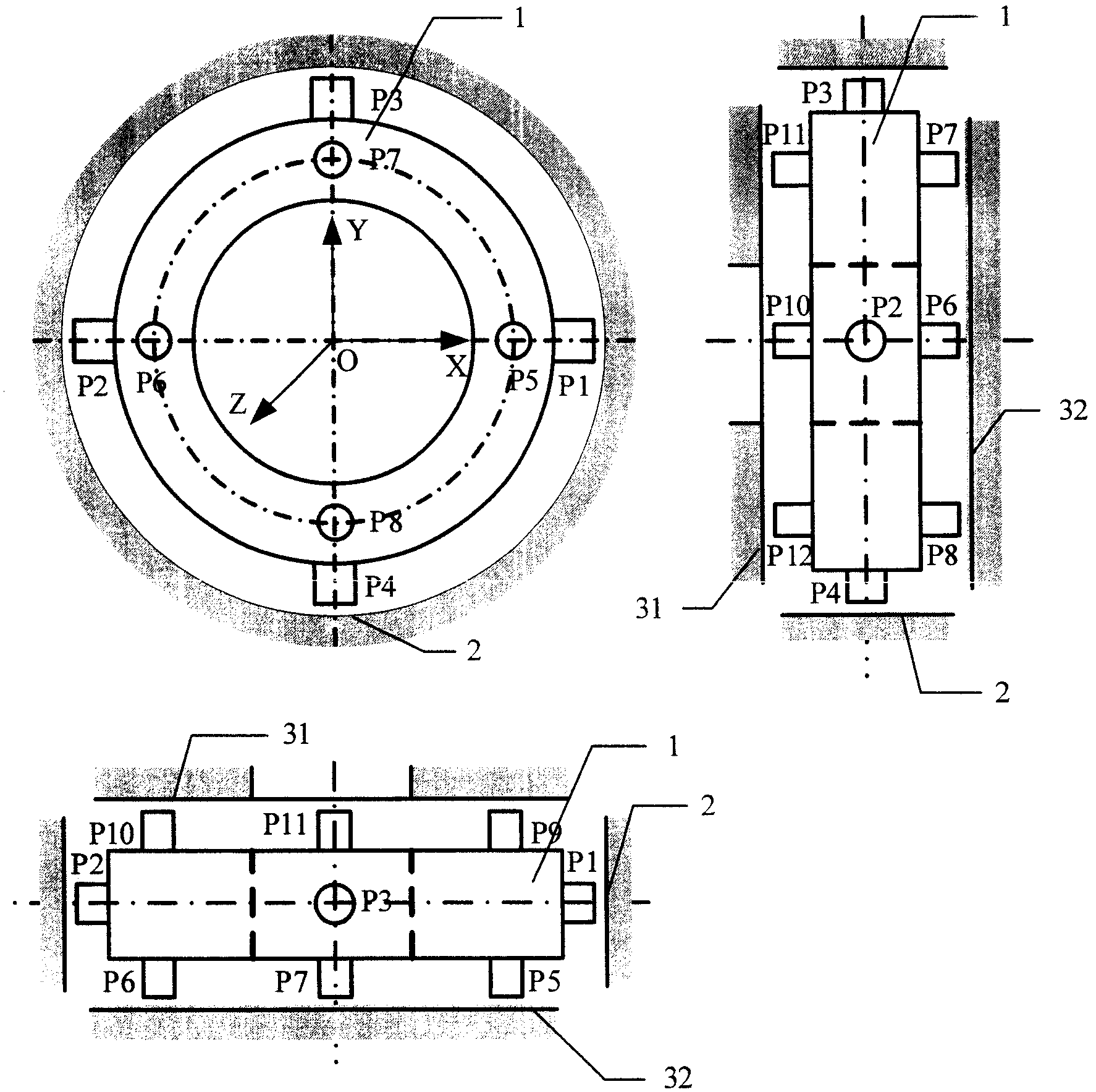
Technical solution of the present invention is: it is by the radial transducer probe of 4 differential configuration surveying directions X and the displacement of Y direction (P1~P4) and corresponding metering circuit thereof, (P5~P12) and corresponding metering circuit thereof are formed to survey the axial sensor probe of 8 differential configuration of Z direction displacement, (P1~P12) and corresponding metering circuit thereof all are integrated in the sensor housing for 12 sensor probes, wherein radial transducer probe P1 and P2 partner along X-direction, the both direction that lays respectively at X-axis becomes 180 ° of angles, and its metering circuit is exported one tunnel differentiated voltage signal; P3 and P4 partner along Y direction, and the both direction that lays respectively at X-axis becomes 180 ° of angles, and its metering circuit is exported one tunnel differentiated voltage signal, and two paths of differential signals is represented the translation of magnetic bearing rotor directions X and Y direction respectively; Axial sensor probe P5 and P9 partner along Z-direction, and the both direction that lays respectively at the Z axle becomes 180 ° of angles, and its metering circuit is exported one tunnel differentiated voltage signal; P6 and P10 partner along Z-direction, the both direction that lays respectively at the Z axle becomes 180 ° of angles, its metering circuit is exported one tunnel differentiated voltage signal, and the both direction that the pair of sensors probe that pair of sensors probe and the P6 and P10 of P5 and P9 composition forms lays respectively at X-axis becomes 180 ° of angles; P7 and P11 partner along Z-direction, and the both direction that lays respectively at the Z axle becomes 180 ° of angles, and its metering circuit is exported one tunnel differentiated voltage signal; P8 and P12 partner along Z-direction, and the both direction that lays respectively at the Z axle becomes 180 ° of angles, and its metering circuit is exported one tunnel differentiated voltage signal; The both direction that the pair of sensors probe that pair of sensors probe and the P8 and P12 of P7 and P11 composition forms lays respectively at Y-axis becomes 180 ° of angles, axial 4 road differential signals have all been represented the axial translation of magnetic bearing rotor, the difference of the difference output of the difference output of P5 and P9 metering circuit and P6 and P10 metering circuit has been represented the turn signal of magnetic bearing rotor around X-axis, and the difference of the difference output of the difference output of P7 and P11 metering circuit and P8 and P12 metering circuit has been represented the turn signal of magnetic bearing rotor around Y-axis.
Principle of the present invention is: the present invention will be integrated in the sensor housing by 4 radial passages of certain structural arrangements and the sensor probe and the corresponding metering circuit of 8 axial passages.Testing circuit adopts the constant frequency amplitude modulation, utilize the detection telefault of parallel resonance electric capacity and sensor probe to constitute a shunt-resonant circuit, utilize the high frequency sinusoidal signal of constant amplitude and frequency that the shunt-resonant circuit is encouraged, utilize the variation of the shunt-resonant circuit impedance that eddy current effect formed the change transitions of distance for the sensor probe coil, obtain through detection then and sensor probe and measured body between positional information linear voltage signal.Export 2 road signals by radial transducer, can obtain the translation displacement signal of magnetic bearing rotor directions X, Y direction; 4 road signals by axial sensor output, get its mean value and can obtain axial translation displacement signal, get the difference of two axial sensor outputs on the X-direction, can obtain the turn signal of rotor around Y-axis, get the difference of two axial sensor outputs on the Y direction, can obtain the turn signal of rotor around X-axis, and physical dimension and centroid position according to rotor can obtain sensor at the directions X of two magnetic bearing positions and the equivalent displacement on the Y direction, thereby only just can realize the magnetic bearing rotor is carried out needed three translations of ACTIVE CONTROL and two rotations high Precision Detection of the positional information of totally five degree of freedom with a sensor.
The present invention has utilized eddy detection technology to make up a kind of magnetic bearing displacement transducer, and the present invention's advantage compared with prior art is:
(1) balanced configuration of axial sensor orthogonal directions 4 pairs of sensor probes, the mean value of 4 some displacements is got in axial displacement output, single probe is compared with two probe schemes, can eliminate the error that rotor deflection and finished surface bring effectively, has improved measuring accuracy.
(2) axially many probe configurations have realized the detection of rotor axial translation and rotor directions X, Y direction turn signal simultaneously.
(3) sensors have been realized the variate of axial displacement, have improved the linearity and the temperature stability of axial sensor.
(4) sensors just can provide the rotor position information of needed 5 degree of freedom of magnetic bearing ACTIVE CONTROL, having overcome existing magnetic bearing system needs two displacement transducers to finish the big defective of the volume weight that detection brought of rotor position information, the integrated level and the assembly precision of sensor have been improved, alleviate weight, reduced volume.
(5) sensor measuring circuit of this invention adopts the constant frequency amplitude modulation, and 12 sensor probes adopt same signal source to encourage, and has eliminated the beat frequency that uses between the sensor probe that a plurality of driving source brings and has disturbed, and simplified circuit structure.
Description of drawings
Fig. 1 looks synoptic diagram for outer-rotor structure three of the present invention;
Fig. 2 looks synoptic diagram for inner rotor core three of the present invention;
Fig. 3 is the configuration schematic diagram of the present invention and outer-rotor structure magnetic bearing;
Fig. 4 is a metering circuit theory diagram of the present invention;
Fig. 5 is the wherein drive test amount circuit theory diagrams of Fig. 4.
Embodiment
(form, and the present invention can be designed to internal rotor or outer-rotor structure according to the different structure form of magnetic bearing rotor by P1~P12) and corresponding metering circuit by 12 sensor probes for the current vortex sensor 1 of integrated, five degree of freedom.Outer-rotor structure of the present invention as shown in Figure 1,2 detection faces for the radial transducer probe are the rotor inner surface among the figure, and detection faces is external with respect to the radial transducer probe, P1 and P2 partner along X-direction, and the both direction that lays respectively at X-axis becomes 180 ° of angles.P3 and P4 partner along Y direction, and the both direction that lays respectively at Y-axis becomes 180 ° of angles, is installed on the sensor excircle.8 axial sensor probe (P5~P12) be symmetrically distributed on two end faces of sensor Z-direction, 31,32 is the axial detection faces of sensor; Inner rotor core of the present invention as shown in Figure 2,2 detection faces for radial transducer probe are the rotor outer surface, detection faces is probe internally provided with respect to radial transducer, P1 and P2 partner along X-direction, and P3 and P4 partner along Y direction, are installed on the sensor inner periphery.(P5~P12) be symmetrically distributed on two end faces of sensor Z-direction, 31,32 is the axial detection faces of sensor to 8 axial sensor probes.Consider the size and the protection gap of magnetic bearing, radial transducer probe designs measurement range is 0.25mm~1.25mm, and axial sensor probe designs measurement range is 0.5mm~1.5mm.
P1 and P2 are paired into the variate structure, survey the translation displacement of rotor X-direction; P3 and P4 are paired into the variate structure, survey the translation displacement of rotor Y direction.(P1~P4) output of metering circuit is expressed as respectively 4 radial transducer probes of sensor: u
Xp, u
Xn, u
Yp, u
Yn, the differential output of the metering circuit of sensor radial transducer probe is expressed as:
X-direction: u
Dx=u
Xp-u
XnY direction: u
Dy=u
Yp-u
Yn
8 axial sensor probes (P5 and P9, P6 and P10, P7 and P11, P8 and P12) are configured to 4 pairs of variate structures in twos, be positioned at radial transducer and pop one's head on two end faces of Z direction of corresponding sensor, can measure the axial displacement of 4 points, thereby obtain Z to the translation displacement signal of direction and rotor turn signal around X-axis and Y-axis both direction.If the differential output of axial sensor probe P5, P9 is expressed as u
Axp, the differential output of P6, P10 is expressed as u
Axnm, the differential output of P7, P11 is expressed as u
Ayp, the differential output of P8, P12 is expressed as u
Ayn, then the axial translation output of sensor can be expressed as
Z gets the mean value of axial 4 differential outputs to the translation displacement signal of direction, can eliminate effectively because rotor block rotates the measuring error that caused axial detection faces tilts and axial detection face mismachining tolerance is brought.The rotor of sensor is around the rotation output of X-axis and Y-axis both direction: u
Wx=u
Axp-u
Axn, u
Wy=u
Ayp-u
Ayn
As Fig. 3, be the configuration schematic diagram of the present invention and outer-rotor structure magnetic bearing.1 is the present invention's one eddy current displacement sensor among the figure, and 2 is the radially probe detection faces of sensor, and 31,32 is two axial probe detection faces of sensor, and 4 is an end radial direction magnetic bearing, and 5 is an end radial direction magnetic bearing, and 6 is axial magnetic bearing, and 7 is the magnetic bearing stator axis.If (P8~P12) the installation circular diameter is d to 8 axial sensor probes, and rotor is α around the drift angle of X-axis, and rotor is β around the drift angle of Y-axis, and transducer sensitivity is k
sThen have
Barycenter with rotor is that true origin is set up coordinate system, sensor arbitrarily radially probe (one of P1~P4) center be l to the distance of radial direction magnetic bearing 4
1, be l to the distance of radial direction magnetic bearing 5
2, be l to the distance of the flywheel rotor physique heart
SoUnder the less situation of deflection angle, sin α ≈ tan α ≈ α is arranged, sin β ≈ tan β ≈ β.The barycenter of considering rotor is not in the geometric center of rotor, and the sensor output of then controlling 5 required degree of freedom is expressed as:
The translation of Z-direction:
The rotation of X-direction: u
Wx=u
Axp-u
Axn
The rotation of Y direction: u
Wy=u
Ayp-u
Ayn
The translation of X-direction:
The translation of Y direction:
By the translation of sensor with rotate the equivalent displacement sensor that output can obtain to control needed radial direction magnetic bearing 4 place's X-directions and Y direction and be output as u
1dx, u
1dyThe X-direction at magnetic bearing 5 places and the equivalent displacement sensor of Y direction output u
2dx, u
2dyPromptly have:
(u
1dx u
1dy u
2dx u
2dy)
T=A(u
dx u
dy u
wx u
wy)
T,
Wherein
Be tied to the transition matrix of magnetic bearing coordinate system for sensor coordinates.
As Fig. 4, sensor measuring circuit has adopted the constant frequency amplitude modulation, is made up of LC resonant circuit, peak-detector circuit, buffer circuit and differential amplifier circuit that 1MHz crystal oscillator, push-pull type power amplification circuit, probe and resonant capacitance are formed.It is the sinusoidal signal of the high stability of 1MHz that the 1MHz crystal oscillator produces frequency, and the sinusoidal signal that the push-pull type power amplification circuit produces crystal oscillator is carried out electric current and amplified, and improves its carrying load ability.Sensor probe and resonant capacitance constitute LC resonant tank in parallel, when the natural mode shape of LC resonant tank equals the high-frequency signal frequency of crystal oscillator supply, and the impedance maximum in loop, output voltage is maximum.When the measured body proximity transducer, the equiva lent impedance of sensor changes, the loop off resonance, harmonic peak moves to the both sides, corresponding variation also takes place in output voltage, the LC resonant tank is exported the Amplitude Modulation High Frequency ripple like this, peak-detector circuit converts the Amplitude Modulation High Frequency ripple of LC resonant tank to DC voltage, for reducing the load of metering circuit, improve the quality factor of shunt-resonant circuit, designed the first-level buffer circuit behind the detecting circuit, differential amplifier circuit carries out the common mode interference that differential amplification suppresses circuit to the voltage signal after cushioning.Fig. 5 is the wherein drive test amount circuit theory diagrams of Fig. 4, and the push-pull type power amplification circuit has adopted low-power transistor 9012 and the 9013 two-tube push-pull type export structures of forming.For improving detection efficiency, peak-detector circuit has adopted two multiplication of voltage wave detectors that high speed switch tube 1N60 forms.The voltage follower circuit that operational amplifier TL084 forms is as the buffer circuit between peak-detector circuit and the differential amplifier circuit.Differential amplifier circuit is made up of TL084.
The present invention adopts differential structure, adopts the sensor probe that electrical quantity is identical and mechanical parameter is symmetrical fully, has designed circuit parameter and the structure testing circuit of symmetry fully, has improved temperature, time stability and the linearity of sensor.12 LC resonant tanks that 12 sensor probes become with the resonance capacitance group adopt same exciting signal source to encourage, and have avoided the beat frequency between the sensor probe to disturb, and have saved exciting signal source, have simplified circuit structure.