CN1987404B - Electronic universal testing machine - Google Patents
Electronic universal testing machine Download PDFInfo
- Publication number
- CN1987404B CN1987404B CN2005101116805A CN200510111680A CN1987404B CN 1987404 B CN1987404 B CN 1987404B CN 2005101116805 A CN2005101116805 A CN 2005101116805A CN 200510111680 A CN200510111680 A CN 200510111680A CN 1987404 B CN1987404 B CN 1987404B
- Authority
- CN
- China
- Prior art keywords
- testing machine
- moving beam
- electronic universal
- load sensor
- universal testing
- Prior art date
- Legal status (The legal status is an assumption and is not a legal conclusion. Google has not performed a legal analysis and makes no representation as to the accuracy of the status listed.)
- Expired - Lifetime
Links
Images


Landscapes
- Investigating Strength Of Materials By Application Of Mechanical Stress (AREA)
Abstract
本发明公开了一种电子万能试验机,包括移动横梁,与移动横梁相连的驱动装置,该驱动装置驱动移动横梁实现加载;该试验机包括:小负荷传感器,与所述移动横梁相连;小负荷拉伸夹具,与所述小负荷传感器相连。外附小负荷传感器主机结构通过对移动横梁的延伸,利用大负荷传感器试验空间的驱动系统,通过传动系统带动滚珠丝杠,从而驱动移动横梁实现加载,进行不同负荷测量范围的力学性能试验。解决了现有电子万能试验机结构“超出传感器有效测量范围下限的试验无法完成”的共性问题,且操作简便。
The invention discloses an electronic universal testing machine, which comprises a moving beam and a driving device connected with the moving beam, and the driving device drives the moving beam to realize loading; the testing machine includes: a small load sensor connected with the moving beam; a small load sensor A tensioning fixture, connected to the small load cell. The host structure with external small load sensor extends the moving beam, utilizes the drive system of the large load sensor test space, and drives the ball screw through the transmission system, thereby driving the moving beam to achieve loading, and performing mechanical performance tests of different load measurement ranges. It solves the common problem of "the test beyond the lower limit of the effective measurement range of the sensor cannot be completed" in the structure of the existing electronic universal testing machine, and is easy to operate.
Description
技术领域technical field
本发明涉及一种电子万能试验机,具体地说,涉及测量范围广、操作简便的电子万能试验机。The invention relates to an electronic universal testing machine, in particular to an electronic universal testing machine with wide measuring range and easy operation.
背景技术Background technique
传统的一种单空间结构的电子万能试验机主机如图1所示,其工作原理为,驱动系统16通过传动系统15带动滚珠丝杠13,从而驱动移动横梁11实现加载,被测试件夹在夹具14上,被测试件的负荷由传感器12测量。本结构的缺点如下:超出传感器有效测量范围下限的试验无法完成;比如300kN电子万能试验机,其有效测量范围为0.6~300kN,对负荷小于0.6kN的试验项目无法实现;电子万能试验机要做拉伸、压缩、弯曲等不同项目的试验,每种项目的试验夹具不同,在一个空间内完成不同的试验项目,要更换相应项目的夹具,操作繁琐。A traditional electronic universal testing machine with a single-space structure is shown in Figure 1. Its working principle is that the
图2显示了差荷双空间(夹具24之间为大负荷工作空间,夹具28之间为小负荷工作空间)结构的电子万能试验机主机,其大负荷工作空间的工作原理同图1结构,小负荷工作空间的驱动、传动一直到移动横梁21的动作同图1,被测试件夹在夹具28上,被测试件的负荷由小负荷传感器27测量。该结构虽然解决了图1结构的第一个问题,但在设备上部进行小负荷试验需要踩梯台操作,操作不便。Fig. 2 shows the electronic universal testing machine host with a structure of differential load double space (large load working space between
图3为等荷双空间(夹具34之间为拉伸工作空间,夹具37之间为压缩、弯曲工作空间)结构的电子万能试验机主机,其工作原理同图1结构,夹具34之间用来做拉伸试验,夹具37之间用来做压缩、弯曲试验。上下空间共用负荷传感器32进行测量。该结构虽然解决了图1结构的第二个问题,但超出传感器有效测量范围下限的试验无法完成;比如300kN电子万能试验机,其有效测量范围为0.6~300kN,对负荷小于0.6kN的试验项目无法实现;同时图2结构所描述的在设备上部操作需要踩梯台的不便,但该结构可以将夹具34与夹具37上下调换,将频繁使用的夹具置于下部可以减轻操作繁琐性。Fig. 3 is the electronic universal testing machine mainframe of equal load double space (stretching work space between
发明内容Contents of the invention
本发明的目的在于,提供一种电子万能试验机,以克服现有电子万能试验机超出传感器有效测量范围下限的试验无法完成且操作繁琐的技术问题。The purpose of the present invention is to provide an electronic universal testing machine to overcome the technical problems that the existing electronic universal testing machine cannot complete the test beyond the lower limit of the effective measurement range of the sensor and is cumbersome to operate.
为了达到上述目的,本发明的技术方案如下:In order to achieve the above object, technical scheme of the present invention is as follows:
一种电子万能试验机,包括移动横梁,与移动横梁相连的驱动装置,该驱动装置驱动移动横梁实现加载;该试验机包括:小负荷传感器,与所述移动横梁相连;小负荷拉伸夹具,与所述小负荷传感器相连。An electronic universal testing machine, comprising a moving beam, a driving device connected to the moving beam, the driving device drives the moving beam to realize loading; the testing machine includes: a small load sensor, connected with the moving beam; a small load tensile fixture, Connected to the small load sensor.
外附小负荷传感器主机结构通过对移动横梁的延伸,利用大负荷传感器试验空间的驱动系统,通过传动系统带动滚珠丝杠,从而驱动移动横梁实现加载,进行不同负荷测量范围的力学性能试验。解决了现有电子万能试验机结构“超出传感器有效测量范围下限的试验无法完成”的共性问题,且操作简便。The host structure with external small load sensor extends the moving beam, utilizes the drive system of the large load sensor test space, and drives the ball screw through the transmission system, thereby driving the moving beam to achieve loading, and performing mechanical performance tests of different load measurement ranges. It solves the common problem of "the test beyond the lower limit of the effective measurement range of the sensor cannot be completed" in the structure of the existing electronic universal testing machine, and is easy to operate.
该试验机包括大负荷传感器,连接在所述移动横梁上。The testing machine includes a large load cell attached to the moving beam.
该试验机包括弯曲夹具,与所述大负荷传感器相连。The testing machine includes a bending fixture connected to the large load cell.
所述驱动装置包括依次相连的驱动系统、传动系统和滚珠丝杠。The driving device includes a driving system, a transmission system and a ball screw connected in sequence.
所述大负荷拉伸夹具安装在该试验机的下空间。The large-load tensile fixture is installed in the lower space of the testing machine.
所述弯曲夹具安装在该试验机的下空间。The bending fixture is installed in the lower space of the testing machine.
附图说明Description of drawings
图1为一种现有的单空间结构的电子万能试验机主机结构图;Fig. 1 is a kind of structure diagram of the host computer of the electronic universal testing machine of existing single-space structure;
图2为另一种现有的差荷双空间的电子万能试验机主机结构图;Fig. 2 is another kind of existing electronic universal testing machine host structure diagram of differential load double space;
图3为另一种现有的等荷双空间的电子万能试验机主机结构图;Fig. 3 is another kind of existing electronic universal testing machine host structure diagram of equal load double space;
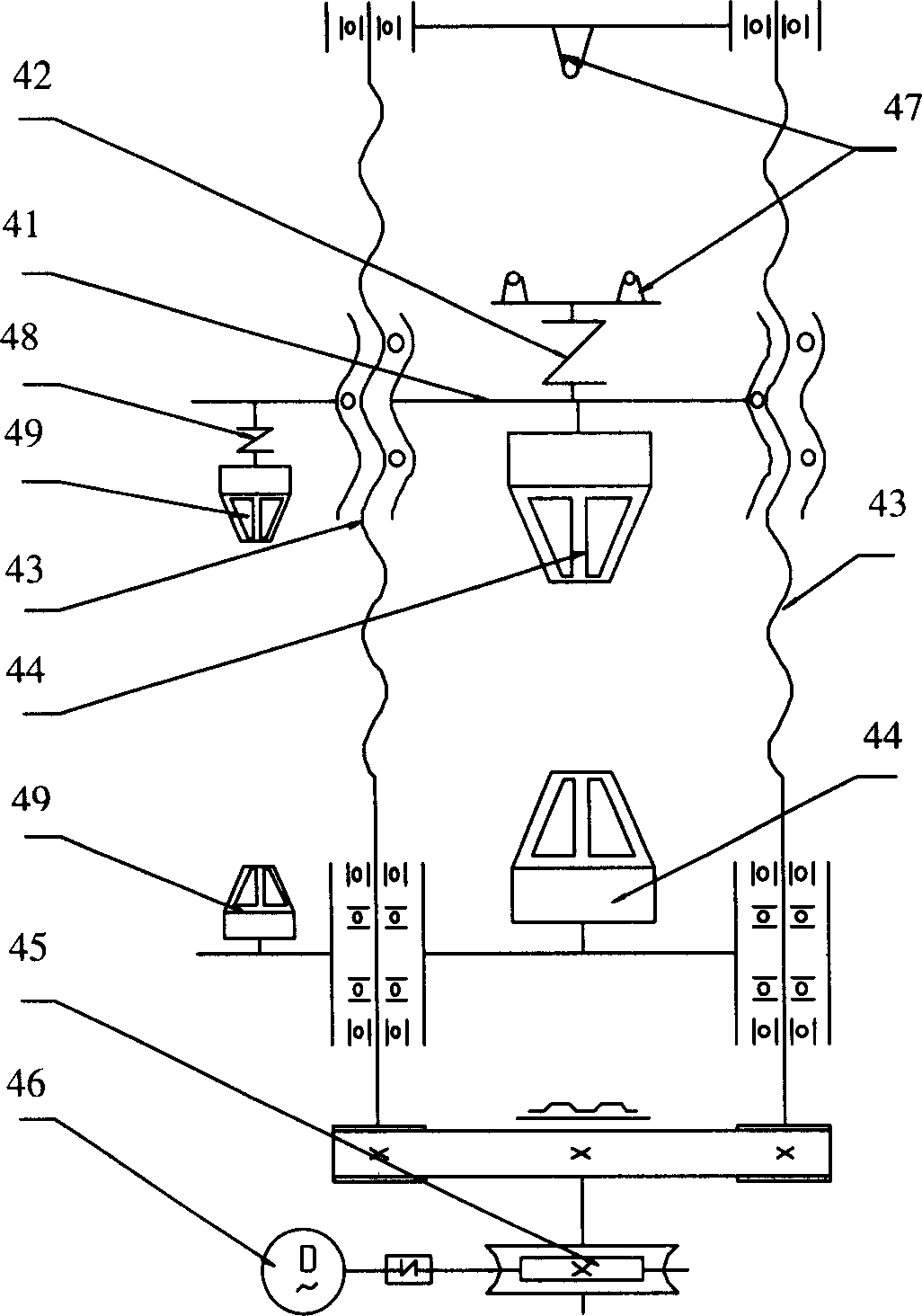
图4为本发明的电子万能试验机主机结构图;Fig. 4 is the electronic universal testing machine host structural diagram of the present invention;
具体实施方式Detailed ways
下面根据图4,给出本发明的较好实施例,并予以详细描述,使能更好地理解本发明的功能、特点。Below, according to FIG. 4 , a preferred embodiment of the present invention is given and described in detail, so that the functions and characteristics of the present invention can be better understood.
图4为外附传感器三空间(大负荷拉伸夹具44之间为大负荷拉伸工作空间,弯曲夹具47之间为大负荷压缩、弯曲工作空间,夹具44之间为小负荷拉伸工作空间)结构,该电子万能试验机,包括移动横梁41,与移动横梁41相连的滚珠丝杠43、传动系统45和驱动系统46;该试验机包括:小负荷传感器48,与所述移动横梁41相连;小负荷拉伸夹具49,与所述小负荷传感器48相连。外附小负荷传感器48主机结构通过对移动横梁41的延伸,利用大负荷传感器42试验空间的驱动系统46,通过传动系统45带动滚珠丝杠43,从而驱动移动横梁41实现加载,进行不同负荷测量范围的力学性能试验。Fig. 4 is the three spaces of the external sensor (the large-load stretching work space is between the large-
比如300kN电子万能试验机而言,其有效测量范围为600~300000N,对于小于600N的试验项目,在外部增加1000N负荷传感器(其有效测量范围为2~1000N),有效测量范围扩展到了2~300000N。这样就可以轻而易举地解决了现有电子万能试验机结构“超出传感器有效测量范围下限的试验无法完成”的共性问题。For example, for a 300kN electronic universal testing machine, its effective measurement range is 600-300000N. For test items less than 600N, a 1000N load sensor is added externally (its effective measurement range is 2-1000N), and the effective measurement range is extended to 2-300000N. . In this way, the common problem of "the test beyond the lower limit of the effective measurement range of the sensor cannot be completed" in the structure of the existing electronic universal testing machine can be easily solved.
300kN电子万能试验机的高度基本在2.3~2.5米之间,小负荷试验如果扩展到上空间(如图2),人的高度站着根本无法操作,必须通过辅助手段才能实现操作,而外附传感器结构的操作高度在0.65~1米之间,操作者坐下即可完成试验操作,既舒适又便捷。The height of the 300kN electronic universal testing machine is basically between 2.3 and 2.5 meters. If the small load test is extended to the upper space (as shown in Figure 2), it is impossible to operate standing at the height of a person. It must be operated through auxiliary means. The operating height of the sensor structure is between 0.65 and 1 meter, and the operator can complete the test operation by sitting down, which is comfortable and convenient.
另外,根据使用的频繁程度,选择将夹具44或夹具47装在下空间,避免了图1结构操作不便的问题。In addition, according to the frequency of use, the
以上所述的,仅为本发明的较佳实施例,并非用以限定本发明的范围,即凡是依据本发明申请的权利要求书及说明书内容所作的简单、等效变化与修饰,皆落入本发明专利的权利要求保护范围。The above are only preferred embodiments of the present invention, and are not intended to limit the scope of the present invention, that is, all simple and equivalent changes and modifications made according to the claims and descriptions of the present application shall fall within the scope of the present invention. The protection scope of the patent claims of the present invention.
Claims (4)
Priority Applications (1)
| Application Number | Priority Date | Filing Date | Title |
|---|---|---|---|
| CN2005101116805A CN1987404B (en) | 2005-12-20 | 2005-12-20 | Electronic universal testing machine |
Applications Claiming Priority (1)
| Application Number | Priority Date | Filing Date | Title |
|---|---|---|---|
| CN2005101116805A CN1987404B (en) | 2005-12-20 | 2005-12-20 | Electronic universal testing machine |
Publications (2)
| Publication Number | Publication Date |
|---|---|
| CN1987404A CN1987404A (en) | 2007-06-27 |
| CN1987404B true CN1987404B (en) | 2010-10-06 |
Family
ID=38184284
Family Applications (1)
| Application Number | Title | Priority Date | Filing Date |
|---|---|---|---|
| CN2005101116805A Expired - Lifetime CN1987404B (en) | 2005-12-20 | 2005-12-20 | Electronic universal testing machine |
Country Status (1)
| Country | Link |
|---|---|
| CN (1) | CN1987404B (en) |
Cited By (2)
| Publication number | Priority date | Publication date | Assignee | Title |
|---|---|---|---|---|
| CN102507327A (en) * | 2011-10-11 | 2012-06-20 | 浙江健力机动车部件有限公司 | Instrument for detecting strength of welding points of check rings of synchronous belt wheel |
| CN108120631A (en) * | 2016-11-30 | 2018-06-05 | 镇江石鼓文智能化系统开发有限公司 | A kind of safe digital display gate-type electronic universal tester |
Families Citing this family (4)
| Publication number | Priority date | Publication date | Assignee | Title |
|---|---|---|---|---|
| CN102721603A (en) * | 2012-06-20 | 2012-10-10 | 新疆维吾尔自治区计量测试研究院 | Electronic universal tester |
| CN103278377A (en) * | 2013-06-05 | 2013-09-04 | 南通市华海铸造有限公司 | New-type electronic universal material testing machine |
| CN108195678A (en) * | 2018-02-08 | 2018-06-22 | 丹阳市鼎新机械设备有限公司 | A kind of device for testing tensile strength of metal wire |
| CN110057654A (en) * | 2019-05-16 | 2019-07-26 | 苏州汇才土水工程科技有限公司 | A kind of New universal material test machine |
Citations (5)
| Publication number | Priority date | Publication date | Assignee | Title |
|---|---|---|---|---|
| US5948994A (en) * | 1998-04-02 | 1999-09-07 | Jen; Ming-Hwa R. | Multi-functional test machine |
| CN1462871A (en) * | 2003-06-26 | 2003-12-24 | 上海申联试验机厂 | Three degree of freedom microcomputer controlled universal tester |
| US6679124B2 (en) * | 2000-06-06 | 2004-01-20 | Mts Systems Corporation | Statistically rigid and dynamically compliant material testing system |
| CN2612942Y (en) * | 2003-05-12 | 2004-04-21 | 深圳市新三思计量技术有限公司 | Double space tester |
| CN2674430Y (en) * | 2003-03-25 | 2005-01-26 | 上海华龙测试仪器有限公司 | Microcomputer controlled electronic universal tester |
-
2005
- 2005-12-20 CN CN2005101116805A patent/CN1987404B/en not_active Expired - Lifetime
Patent Citations (5)
| Publication number | Priority date | Publication date | Assignee | Title |
|---|---|---|---|---|
| US5948994A (en) * | 1998-04-02 | 1999-09-07 | Jen; Ming-Hwa R. | Multi-functional test machine |
| US6679124B2 (en) * | 2000-06-06 | 2004-01-20 | Mts Systems Corporation | Statistically rigid and dynamically compliant material testing system |
| CN2674430Y (en) * | 2003-03-25 | 2005-01-26 | 上海华龙测试仪器有限公司 | Microcomputer controlled electronic universal tester |
| CN2612942Y (en) * | 2003-05-12 | 2004-04-21 | 深圳市新三思计量技术有限公司 | Double space tester |
| CN1462871A (en) * | 2003-06-26 | 2003-12-24 | 上海申联试验机厂 | Three degree of freedom microcomputer controlled universal tester |
Non-Patent Citations (2)
| Title |
|---|
| JP平2-203240A 1990.08.13 |
| JP平7-72058A 1995.03.17 |
Cited By (2)
| Publication number | Priority date | Publication date | Assignee | Title |
|---|---|---|---|---|
| CN102507327A (en) * | 2011-10-11 | 2012-06-20 | 浙江健力机动车部件有限公司 | Instrument for detecting strength of welding points of check rings of synchronous belt wheel |
| CN108120631A (en) * | 2016-11-30 | 2018-06-05 | 镇江石鼓文智能化系统开发有限公司 | A kind of safe digital display gate-type electronic universal tester |
Also Published As
| Publication number | Publication date |
|---|---|
| CN1987404A (en) | 2007-06-27 |
Similar Documents
| Publication | Publication Date | Title |
|---|---|---|
| CN102589989B (en) | Single-shaped pulling-pressing double-function creepmeter | |
| CN104210913B (en) | Elevator no-load balance coefficient detection device | |
| CN105953712A (en) | Shaft-like member loading deformation testing device and testing method | |
| CN206787816U (en) | Guard against error railing horizontal thrust load testing machine | |
| CN1987404B (en) | Electronic universal testing machine | |
| CN102004021B (en) | Static stiffness testing method for horizontal machining centre | |
| CN208902336U (en) | A kind of pull and push dynamometer detection device | |
| CN104458422A (en) | Material mechanical multi-functional combined experiment table | |
| CN202101810U (en) | Tensile test device used for comparing calibration of stress sensor | |
| CN108896382B (en) | Mechanical load testing device for variable working conditions | |
| CN103900450B (en) | Impact specimen side swell increment measurement apparatus | |
| CN110617055A (en) | Wireless integrated beam-pumping well indicator diagram testing device | |
| CN101556133B (en) | Thickness measuring device for wall board | |
| CN211347746U (en) | Toothbrush Tensile Bending Tester | |
| CN109946009A (en) | A kind of device for testing tensile force | |
| CN209624740U (en) | A remanufactured motor detection device | |
| CN204679191U (en) | Pull and push dynamometer measures auxiliary stand | |
| CN209525179U (en) | Heat shrinkable film tensile strength testing machine | |
| CN103743506B (en) | A kind of load-measuring device and measuring method thereof | |
| CN2779378Y (en) | Multifunctional experimental instrument for elasticity of material | |
| CN213658206U (en) | Five quiet rigidity testing arrangement | |
| CN110132738A (en) | A bolt pulling force detection device | |
| CN105203308B (en) | A kind of structural model multifunctional loading unit | |
| CN201269726Y (en) | Digital display outside caliper | |
| CN201574745U (en) | A CAN bus equipment tester |
Legal Events
| Date | Code | Title | Description |
|---|---|---|---|
| C06 | Publication | ||
| PB01 | Publication | ||
| C10 | Entry into substantive examination | ||
| SE01 | Entry into force of request for substantive examination | ||
| C14 | Grant of patent or utility model | ||
| GR01 | Patent grant | ||
| C56 | Change in the name or address of the patentee |
Owner name: SHANGHAI HUALONG TEST INSTRUMENTS CORPORATION Free format text: FORMER NAME: HUALONG DETECTOR CO., LTD., SHANGHAI |
|
| CP01 | Change in the name or title of a patent holder |
Address after: 201202 Shanghai City, Pudong Chuansha Economic Zone, Sichuan Road No. 389 Patentee after: SHANGHAI HUALONG TEST INSTRUMENTS Co.,Ltd. Address before: 201202 Shanghai City, Pudong Chuansha Economic Zone, Sichuan Road No. 389 Patentee before: Shanghai Hualong Test Instruments Co.,Ltd. |
|
| CP03 | Change of name, title or address |
Address after: 201201 No. 389 Chuanhong Road, Chuansha Town, Pudong New Area, Shanghai Patentee after: Shanghai Hualong Test Instruments Co.,Ltd. Address before: No. 389 Chuanhong Road, Chuansha Economic Park, Pudong, Shanghai Patentee before: SHANGHAI HUALONG TEST INSTRUMENTS Co.,Ltd. |
|
| CP03 | Change of name, title or address | ||
| CX01 | Expiry of patent term |
Granted publication date: 20101006 |
|
| CX01 | Expiry of patent term |