CN200977983Y - A foldable handlebar device for a power vehicle - Google Patents
A foldable handlebar device for a power vehicle Download PDFInfo
- Publication number
- CN200977983Y CN200977983Y CN 200620147686 CN200620147686U CN200977983Y CN 200977983 Y CN200977983 Y CN 200977983Y CN 200620147686 CN200620147686 CN 200620147686 CN 200620147686 U CN200620147686 U CN 200620147686U CN 200977983 Y CN200977983 Y CN 200977983Y
- Authority
- CN
- China
- Prior art keywords
- middle rod
- rod
- locking
- lock
- power vehicle
- Prior art date
- Legal status (The legal status is an assumption and is not a legal conclusion. Google has not performed a legal analysis and makes no representation as to the accuracy of the status listed.)
- Expired - Fee Related
Links
- 238000003780 insertion Methods 0.000 claims description 12
- 230000037431 insertion Effects 0.000 claims description 12
- 230000006835 compression Effects 0.000 claims description 10
- 238000007906 compression Methods 0.000 claims description 10
- 230000000903 blocking effect Effects 0.000 claims description 5
- 238000000926 separation method Methods 0.000 claims description 2
- 230000032258 transport Effects 0.000 abstract description 2
- 238000005452 bending Methods 0.000 description 9
- 238000010586 diagram Methods 0.000 description 5
- 230000002452 interceptive effect Effects 0.000 description 2
- 238000000034 method Methods 0.000 description 2
- 230000007812 deficiency Effects 0.000 description 1
- 238000005516 engineering process Methods 0.000 description 1
- 239000000446 fuel Substances 0.000 description 1
- 230000005484 gravity Effects 0.000 description 1
- 239000000725 suspension Substances 0.000 description 1
Images


Landscapes
- Motorcycle And Bicycle Frame (AREA)
Abstract
Description
技术领域:Technical field:
本实用新型涉及机动车技术领域,特指一种电力动力车的可折叠车把装置。The utility model relates to the technical field of motor vehicles, in particular to a foldable handlebar device of an electric power vehicle.
前景技术:Foreground technology:
目前的机动力主要包括燃油车和电力车,由于电力车具有噪声小,成本低,且不会产生废气等优点为,近年来已经不断的应用于人们的日常生活、工作中。但是目前的电力动力车体型较大,无法在一些人流较大的场合工作,例如超市、医院内工作。另外,由于目前电动车各部件之间的连接比较稳固,难以实现折叠放置,其运输及放置时需要占据较大的空间,并且其功能单一,难以法满足人们的需求。The current motor vehicles mainly include fuel vehicles and electric vehicles. Because electric vehicles have the advantages of low noise, low cost, and no exhaust gas, they have been continuously used in people's daily life and work in recent years. However, the current electric powered vehicles are too large to work in places with a large flow of people, such as supermarkets and hospitals. In addition, due to the relatively stable connection between the various components of the current electric vehicle, it is difficult to realize folding and placement. It needs to occupy a large space during transportation and placement, and its function is single, so it is difficult to meet people's needs.
实用新型内容:Utility model content:
本实用新型所要解决的技术问题就是针对现有技术的不足而提供一种动力车的可折叠车把装置,通过这种装置可增强动力车的实用操作性,给使用者带来更多的便利。The technical problem to be solved by the utility model is to provide a foldable handlebar device for a power vehicle in view of the deficiencies in the prior art, through which the practical operability of the power vehicle can be enhanced, and more convenience can be brought to users .
为解决上述技术问题,本实用新型采用如下技术方案:该装置包括中杆部以及位于中杆部上下两端的把手部和下端部,中杆部的下端与下端部铰结,并且在中杆部与下端部之间安装有锁扣件。In order to solve the above-mentioned technical problems, the utility model adopts the following technical scheme: the device includes a middle rod part, a handle part and a lower end part located at the upper and lower ends of the middle rod part, the lower end of the middle rod part is hinged with the lower end part, and the middle rod part A locking piece is installed between the lower end and the lower end.
所述的中杆部与下端部之间还设置有回位机构以及止回机构。A return mechanism and a non-return mechanism are also provided between the middle rod portion and the lower end portion.
所述的锁扣件包括:锁杆、锁套以及可与锁杆形成插接配合的锁孔,锁杆位于固定在中杆部上的锁套内,锁杆具有一卡扣部,锁套上成型有与卡扣部配合的两个卡槽,锁孔固定设置的下端部上,通过锁杆卡扣部分别与两个卡槽的配合实现锁杆与锁孔的插接或分离。The lock piece includes: a lock rod, a lock sleeve and a lock hole that can form an insertion fit with the lock rod. The lock rod is located in the lock sleeve fixed on the middle rod. The upper part is formed with two card slots matching with the buckle part, and on the lower end part where the lock hole is fixedly arranged, the lock bar and the lock hole are inserted or separated through the cooperation of the lock bar buckle part with the two card slots respectively.
所述的回位机构包括:固定在下端部上的回位压簧和安装在中杆部上的滚轴,于下端部上延伸有一延伸板,回位压簧的下端固定在此延伸板上,其上端抵压于滚轴上。The return mechanism includes: a return compression spring fixed on the lower end and a roller installed on the middle rod, an extension plate extends from the lower end, and the lower end of the return compression spring is fixed on the extension plate , the upper end of which is pressed against the roller.
所述的止回机构包括:固定在下端部上的挡片以及铰结于中杆部上的拨杆,挡片具有一弯折部,拨杆具有可与该弯折部形成干涉的弯折卡钩,并且在拨杆上设置有一根拉簧。The non-return mechanism includes: a block fixed on the lower end and a driving lever hinged on the middle rod, the blocking plate has a bent part, and the driving rod has a bending that can interfere with the bent part Grab hook, and an extension spring is arranged on the driving lever.
所述的把手部与中杆部之间设置有离合器。A clutch is arranged between the handle part and the middle rod part.
本实用新型的车把可以根据需要在使用时打开或将其折叠放置,以减少车体所占用的空间和满足使用者在不同场合下的使用需求。本实用新型采用上述技术方案后,车把除了具有普通的方向操控功能外,其还具有了如下的优点:The handlebar of the utility model can be opened or folded when used as required, so as to reduce the space occupied by the vehicle body and meet the needs of users in different occasions. After the utility model adopts the above-mentioned technical scheme, the handlebar has the following advantages in addition to the ordinary direction control function:
首先,车把具有可折叠功能,使用者可以在不需要情况下将车把折叠起来,这样可以减小车体的体积,便于使用者运输、放置。First of all, the handlebar has a foldable function, and the user can fold the handlebar when it is not needed, so that the volume of the car body can be reduced, and it is convenient for the user to transport and place it.
其次,本实用新型车把部分采用折叠功能后,使用者就可以根据需要选择拖拉车体或者直接乘坐车体,或者将车体的车把旋转、折叠起来,减小车体所占用的空间。Secondly, after the handlebar part of the utility model adopts the folding function, the user can choose to drag the car body or ride directly on the car body according to needs, or rotate and fold the handlebar of the car body to reduce the space occupied by the car body.
最后,本实用新型采用了一系列人性化设计,提高使用的舒适性和方便性。Finally, the utility model adopts a series of humanized designs to improve the comfort and convenience of use.
附图说明:Description of drawings:
下面结合附图对本实用新型作进一步的说明:Below in conjunction with accompanying drawing, the utility model is further described:
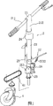
图1是本实用新型结构图;Fig. 1 is a structural diagram of the utility model;
图2是本实用新型中离合器部分的结构图;Fig. 2 is the structural diagram of clutch part in the utility model;
图3是本实用新型中回位机构部分的结构图;Fig. 3 is a structural diagram of the return mechanism part in the utility model;
图4是本实用新型中锁扣件部分的结构图;Fig. 4 is a structural diagram of the locking part in the utility model;
图5是本实用新型中止会机构部分的结构图。Fig. 5 is a structural diagram of the suspension mechanism of the utility model.
具体实施方式:Detailed ways:
见图1,本实用新型的车把2包括:把手部21、中杆部22和下端部23。把手部21和下端部23分别位于中杆部22上下两端的,其中把手部21通过离合器24与中杆部22连接,中杆部22的下端与下端部23铰结;在中杆部22与下端部23之间安装有锁扣件25、回位机构26以及止回机构27。Referring to FIG. 1 , the handlebar 2 of the present invention includes: a
把手部21包括:呈“丁”字交叉固定连接在一起的横向方向杆211和竖轴212,其中方向杆211的两端设置供人体握持的动力手柄和制动手柄,动力手柄与电动车的动力源之间形成电连接,以通过动力手柄控制车体运动,制动手柄与车体的刹车件连动。The
中杆部22与下端部23之间采用铰结结构,这样中杆部22就可以绕铰支点转动,这种设计的优点就是,当使用者拖动整个车体运行时,把手部21可通过中杆部22的旋转达到适合使用者拖动的角度,便于具有不同身高的使用者使用。当然,当使用者直接驾驶本实用新型时,把手部21及中杆部22部不能仍保持可转动状态,此时需要通过锁扣件25将中杆部22与下端部23固定,使两者之间形成固定连接,无法相对旋转。A hinge structure is adopted between the
所述的锁扣件25包括:锁杆251、锁套252以及可与锁杆251形成插接配合的锁孔253,锁杆251位于固定在中杆部22上的锁套252内,锁杆251具有一卡扣部2511,锁套252上成型有与卡扣部2511配合的两个卡槽2521、2522,锁孔253固定设置的下端部23上,通过锁杆251卡扣部2511分别与两个卡槽2521、2522的配合实现锁杆251与锁孔253的插接或分离。这样就可以实现中杆部22与下端24之间是保持固定连接,还是处于可转动状态。The
当中杆部22与下端部23之间处于可转动状态时,为了减轻使用者的受力以及令转动后的中杆部22可以及时回位,本实用新型采用了回位机构26。When the
参见图3,所述的回位机构26包括:固定在下端部23上的回位压簧261和安装在中杆部22上的滚轴262,于下端部23上延伸有一延伸板263,回位压簧261的下端固定在此延伸板263上,其上端抵压于滚轴262上。使用者向前下压把手部21牵动整个车辆行进。此时中杆部22将带动把手部21向前倾斜,同时滚轴262将向下压住回位压簧261的上端面,令回位压簧261压缩。这样回位压簧261将产生一个弹力,向上推滚轴262,使其回位。这样使用者在下压把手部21的过程中,回位弹簧261将消化掉把手部21在倾斜过程中的重力,使用者只需要施加少许的压力就可将把手部21保持在一定倾斜角度。另外,当使用者松凯把手部21后,在回位压簧261的作用下,中杆部22在惯性作用下回位过度,反向转动到车座方向。为避免车把在在回位的过程中与车座或其他部件碰撞,本实用新型设置了止回机构27。Referring to Fig. 3, the
所述的止回机构27包括:固定在下端部23上的挡片271以及铰结于中杆部22上的拨杆272,挡片271具有一弯折部2711,拨杆272具有可与该弯折部2711形成干涉的弯折卡钩2721。当中杆部22在回位机构26作用下回归到竖直状态时,由于拨杆272弯折部2711与弯折卡钩2721形成干涉,确保中杆部22无法继续过度回位,从而保持在竖直状态。另外,由于止回机构27中的拨杆271与中杆部22之间为铰结结构,拨杆271可以旋转,当需要将中杆部22及把手部21向车座部分折叠时,可拨动拨杆271,令弯折部2711旋转至无法与弯折卡钩2721产生干涉的角度,此时向车座方向施力,就可以令把手部21及中杆部22完全叠放在车座上,这样可令整个车体折叠的体积更小。The
为了保持弯折部2711处于可与弯折卡钩2721产生干涉的角度,在拨杆272上设置有一根拉簧2722。In order to keep the
参见图2,离合器24可控制把手部21与中杆部212是否连动的装置。其包括:插入端241、接入端242、压簧243以及套体244,其中插入端241固设于把手部21与中杆部22连接的竖轴212末端,其具有一横截面为方形的插入轴2411,接入端242固设于中杆部22的上端,其具有与插入轴2411对应的方形孔2421,且在方形孔2421的外围成型有外缘2422,与外缘2422上形成有缺口槽2423,套体244由竖轴212向下套设于插入端241与接入端242的接合部,套体244具有一底盖2411,该底盖2441套设在中杆部22上,并固定在套体244底面的开口端。底盖2441的中间所开设的通孔部延伸有与外缘2422缺口槽2423对应的卡缘2442,压簧243位于插入端241与接入端242之间。按照上述结构方式配合好的离合器24将把手部21的竖轴212与中杆部22连接起来,通过插入轴2411与方形孔2421之间的配合令其之间不会产生相对旋转,这样只要转动把手部21就可驱动中杆部22以及与中杆部22连接的下端部23,从而驱动前轮转向。在折叠车辆时,需要将把手部21旋转180度,令车体可以折叠的更加紧密。此时转动离合器24的套体244,套体带动底盖2441旋转,当底盖2441通孔内的卡缘2442旋转到缺口槽2423位置时,底盖2441失去卡缘2442对其的限定,在压簧242的弹力作用下,整个离合器24向上运动,令插入端241的插入轴241 1离开方形孔2421,此时把手部21与中杆部22之间没有连动,转动把手部21不会带动中杆部22旋转,这样就可以将把手部21旋转180度。Referring to FIG. 2 , the
参见图1,本实用新型使用时安装在电动车机架前梁的前端,并且车把2与前轮4连动,以驱动前轮4的转动。本实用新型的前轮4可以采用单轮结构,也可采用双轮结构。车把2的下端部23可转动安装于电动车机架前梁的前端,并且在下端部23上设置有一个齿轮,通过链条41将下端部23与前轮4连接,实现车把2与前轮4之间的连动,以驱动前轮4的转向。Referring to Fig. 1, the utility model is installed on the front end of the front beam of the electric vehicle frame during use, and the handlebar 2 is linked with the
当然,以上所述仅仅为本实用新型的实施例而已,并非来限制本实用新型实施范围,凡依本实用新型申请专利范围所述的构造、特征及原理所做的等效变化或修饰,均应包括于本实用新型申请专利范围内。Of course, the above descriptions are only embodiments of the present utility model, and are not intended to limit the implementation scope of the present utility model. Should be included in the utility model patent scope.
Claims (6)
Priority Applications (1)
| Application Number | Priority Date | Filing Date | Title |
|---|---|---|---|
| CN 200620147686 CN200977983Y (en) | 2006-10-29 | 2006-10-29 | A foldable handlebar device for a power vehicle |
Applications Claiming Priority (1)
| Application Number | Priority Date | Filing Date | Title |
|---|---|---|---|
| CN 200620147686 CN200977983Y (en) | 2006-10-29 | 2006-10-29 | A foldable handlebar device for a power vehicle |
Publications (1)
| Publication Number | Publication Date |
|---|---|
| CN200977983Y true CN200977983Y (en) | 2007-11-21 |
Family
ID=38978363
Family Applications (1)
| Application Number | Title | Priority Date | Filing Date |
|---|---|---|---|
| CN 200620147686 Expired - Fee Related CN200977983Y (en) | 2006-10-29 | 2006-10-29 | A foldable handlebar device for a power vehicle |
Country Status (1)
| Country | Link |
|---|---|
| CN (1) | CN200977983Y (en) |
Cited By (1)
| Publication number | Priority date | Publication date | Assignee | Title |
|---|---|---|---|---|
| CN101168378B (en) * | 2006-10-29 | 2011-11-30 | 叶振豪 | Foldable handlebar device of power vehicle |
-
2006
- 2006-10-29 CN CN 200620147686 patent/CN200977983Y/en not_active Expired - Fee Related
Cited By (1)
| Publication number | Priority date | Publication date | Assignee | Title |
|---|---|---|---|---|
| CN101168378B (en) * | 2006-10-29 | 2011-11-30 | 叶振豪 | Foldable handlebar device of power vehicle |
Similar Documents
| Publication | Publication Date | Title |
|---|---|---|
| EP1398258B1 (en) | Foldable frame for a tricycle powered by physical force and/or a motor | |
| CN105599845B (en) | A kind of folding stand with vibration absorber | |
| CN200977983Y (en) | A foldable handlebar device for a power vehicle | |
| CN2551232Y (en) | A car for the elderly that helps the elderly to walk and provides them with a rest | |
| CN101168378B (en) | Foldable handlebar device of power vehicle | |
| CN101041360A (en) | Bidirectional folding vehicle | |
| CN2820688Y (en) | Compact folding bicycle | |
| CN112693379A (en) | Manual turnover type seat headrest | |
| CN2908327Y (en) | Scooter | |
| CN207191138U (en) | Turnover mechanism for wheel and stroller frame | |
| CN2841487Y (en) | Folding bicycle | |
| CN2561456Y (en) | Folding structure of a three-fold golf cart | |
| CN2470234Y (en) | Foldable pedal | |
| CN2908315Y (en) | a power car | |
| CN2745847Y (en) | Folding handle bar of bicycle | |
| CN2425677Y (en) | a scooter | |
| CN2679017Y (en) | Folding arrangement | |
| CN101054098B (en) | Power vehicle | |
| CN2693617Y (en) | Rain-proof, sunshine-proof and dustproof vehicle cushion | |
| CN2688165Y (en) | Multifunctional cradles | |
| CN210793480U (en) | Telescopic automobile body and vehicle thereof | |
| CN2818716Y (en) | Angle-adjusting foldable hinge | |
| CN2683484Y (en) | baby stroller | |
| CN2579395Y (en) | Front wheel drive for electric scooters | |
| CN2642643Y (en) | Foldable single-wheel vehicle |
Legal Events
| Date | Code | Title | Description |
|---|---|---|---|
| C14 | Grant of patent or utility model | ||
| GR01 | Patent grant | ||
| C17 | Cessation of patent right | ||
| CF01 | Termination of patent right due to non-payment of annual fee |
Granted publication date: 20071121 Termination date: 20091130 |