CN201014454Y - Vertical life refuse incinerator - Google Patents
Vertical life refuse incinerator Download PDFInfo
- Publication number
- CN201014454Y CN201014454Y CNU2007200836362U CN200720083636U CN201014454Y CN 201014454 Y CN201014454 Y CN 201014454Y CN U2007200836362 U CNU2007200836362 U CN U2007200836362U CN 200720083636 U CN200720083636 U CN 200720083636U CN 201014454 Y CN201014454 Y CN 201014454Y
- Authority
- CN
- China
- Prior art keywords
- chamber
- dual firing
- combustion chamber
- mixing chamber
- burning chamber
- Prior art date
- Legal status (The legal status is an assumption and is not a legal conclusion. Google has not performed a legal analysis and makes no representation as to the accuracy of the status listed.)
- Expired - Lifetime
Links
- 238000002156 mixing Methods 0.000 claims abstract description 27
- 238000002485 combustion reaction Methods 0.000 claims description 30
- 238000010304 firing Methods 0.000 claims description 23
- 230000009977 dual effect Effects 0.000 claims description 21
- 239000010813 municipal solid waste Substances 0.000 claims description 15
- 239000011449 brick Substances 0.000 claims description 6
- 239000000463 material Substances 0.000 claims description 4
- 239000010882 bottom ash Substances 0.000 claims description 3
- 238000005266 casting Methods 0.000 claims description 3
- 238000007599 discharging Methods 0.000 claims description 3
- 230000002093 peripheral effect Effects 0.000 claims description 3
- 229910001220 stainless steel Inorganic materials 0.000 claims description 2
- 239000010935 stainless steel Substances 0.000 claims description 2
- 239000010791 domestic waste Substances 0.000 abstract description 7
- 239000003245 coal Substances 0.000 abstract description 3
- 239000000203 mixture Substances 0.000 abstract description 3
- 238000001035 drying Methods 0.000 abstract 1
- 239000000446 fuel Substances 0.000 abstract 1
- UGFAIRIUMAVXCW-UHFFFAOYSA-N Carbon monoxide Chemical compound [O+]#[C-] UGFAIRIUMAVXCW-UHFFFAOYSA-N 0.000 description 16
- 239000003546 flue gas Substances 0.000 description 16
- 239000007789 gas Substances 0.000 description 9
- 230000000694 effects Effects 0.000 description 3
- 238000004056 waste incineration Methods 0.000 description 3
- 238000000034 method Methods 0.000 description 2
- 239000002245 particle Substances 0.000 description 2
- 231100000614 poison Toxicity 0.000 description 2
- 230000007096 poisonous effect Effects 0.000 description 2
- 238000002360 preparation method Methods 0.000 description 2
- 239000010782 bulky waste Substances 0.000 description 1
- 230000008878 coupling Effects 0.000 description 1
- 238000010168 coupling process Methods 0.000 description 1
- 238000005859 coupling reaction Methods 0.000 description 1
- 125000004122 cyclic group Chemical group 0.000 description 1
- 238000005516 engineering process Methods 0.000 description 1
- 239000004744 fabric Substances 0.000 description 1
- 230000009970 fire resistant effect Effects 0.000 description 1
- 238000002309 gasification Methods 0.000 description 1
- 238000010438 heat treatment Methods 0.000 description 1
- 238000002844 melting Methods 0.000 description 1
- 230000008018 melting Effects 0.000 description 1
- 238000005192 partition Methods 0.000 description 1
- 230000000149 penetrating effect Effects 0.000 description 1
- 239000002893 slag Substances 0.000 description 1
Images

Landscapes
- Incineration Of Waste (AREA)
Abstract
The utility model discloses a vertical domestic waste incinerator that is suitable for being used in incineration treatment of domestic waste in medium and small-scale cities, which comprises a vertical cylinder-shaped body, a first burning chamber and a second burning chamber that are arranged in series from top to bottom. The spherical arch enables the first burning chamber and the second burning chamber tobe separated into two independent burning chambers; a ring-typed mixing chamber is communicated with the first burning chamber and the second burning chamber via a flame port; the lower part of the furnace body is provided with a reburning chamber comprising two rows of tooth-profiled active grate; the lateral surface of the furnace body is provided with a chute which includes a material-pushing mechanism and a rotary drying (mixture) device; the city domestic wastes with low calorific value that is more than or equal to 1200 Kcal / kg can be steadily treated without auxiliary fuels via reasonable first-time and second-time wind distribution; as to the domestic waste with the calorific value less than 1200 Kcal / kg, reliable incineration treatment can also be carried out after pretreatment equipment is equipped or via improvement of calorific value by coal distribution. The utility model has simple and practical structure, and the utility model has the advantages of low cost, easy operation, and perfect control.
Description
[technical field]
The utility model relates to a kind of domestic waste incineration, particularly handles the vertical daily garbage incinerator that needs at vast small and medium-sized cities consumer waste incineration.
[background technology]
The domestic waste incineration that generally adopt present home and abroad is in the majority with various mechanical kiln grate furnaces, this kind furnace type structure complexity, most of fire grate structures belong to the foreign patent product, spare part expense costliness, so this kind type of furnace is applicable to that the bulky refuse incineration plant realizes cogeneration of heat and power.Also has a kind of vertical gasification and melting stove, because of the rubbish that only is suitable for handling high heating value is restricted its application.Present situation on the low side at vast small and medium-sized cities house refuse output, that calorific value is on the low side does not still have the suitable incinerator with its coupling.
[summary of the invention]
The purpose of this utility model is exactly the problem that exists at prior art, in vast, the small city provide a kind of simple and practical, cost is low, easy to operate, vertical daily garbage incinerator that control is perfect.
The purpose of this utility model is achieved in that a kind of vertical daily garbage incinerator, body of heater is the vertical cylinder of an inner lining refractory, one combustion chamber 4 and dual firing chamber's 1 coaxial being disposed in series in the body of heater, one combustion chamber is provided with opens burner 16, dual firing chamber is provided with booster burners 15, the sphere arch 2 of hemisphere face shape is every putting one, on the interface brick wall of dual firing chamber, make a combustion chamber and dual firing chamber be separated into two relatively independent combustion chambers, the peripheral brick of sphere arch is provided with the mixing chamber 3 of annular within the walls, mixing chamber 3 tops are column type, the bottom is conical, mixing chamber is by flame hole 13,14 are communicated with a combustion chamber and dual firing chamber respectively, the body of heater lower disposed has profile of tooth moving grate 5,7, constitute burning chamber 6 between the two, the profile of tooth moving grate is fixed on the swinging axle by staggered profile of tooth fire grate segment to be formed, and locates in the furnace bottom ash chamber again, one combustion chamber periphery is provided with wind air inlet 10 one time, 11, the mixing chamber periphery is provided with secondary wind air inlet 12, and secondary wind air inlet 12 tangentially is communicated with mixing chamber.
Above-mentioned vertical daily garbage incinerator, body of heater side are provided with the chute 8 that pusher is housed, and the entrance point of chute 8 is connected with the discharging opening of revolution oven dry (batching) device 9, and the port of export communicates with a combustion chamber.
Owing to adopt said structure, advance stove rubbish in the furnace high-temperature environment, be subjected to respectively the combustion-supporting effect of a wind sending into by furnace bottom and periphery rapid fire burns, by the air quantity of controlling a wind one combustion room temperature is maintained in 760~850 ℃ of scopes, the interception changed course that the high-temperature flue gas of one combustion chamber upwards is subjected to sphere arch 2 enters mixing chamber by the flame hole 13 of side, and the big particle of carrying secretly in the flue gas returns in the flame because of collision and burns away, burns simultaneously.Enter the high-temperature flue gas of mixing chamber and mix the back is entered top by flame hole 14 dual firing chamber's 1 continuation high-temp combustion with the secondary wind that tangentially enters mixing chamber, by one, the reasonable preparation of secondary wind, can effectively guarantee ignition temperature 〉=850 ℃ of dual firing chamber, combustible component in the flue gas is burnt, poisonous, harmful components are decomposed fully, destroy by fire, guarantee kiln gas qualified discharge after follow-up vent gas treatment, the flue gas that enters mixing chamber 3 makes the big particulate trap of carrying secretly in the flue gas in the process of collision and changed course in stove, reduced the dustiness that kiln gas effectively, alleviated the load of follow-up tail gas treatment device, incineration residue in the one combustion chamber 4 enters burning chamber again by the profile of tooth moving grate of regularly opening 5, under a wind action of preheating, thoroughly burn, the setting of burning chamber again, the controlled burn decrement rate that heats is below 2%, is better than 5% requirement of national Specification.Of the present utility model simple and practical, have the advantage that cost is low, easy to operate, control is perfect.
[description of drawings]
Below in conjunction with drawings and Examples the utility model is described further.
Fig. 1 is a structural representation of the present utility model.
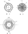
Fig. 2 is the A-A view of Fig. 1.
Fig. 3 is the B-B view of Fig. 1.
Fig. 4 is the C-C view of Fig. 1.
Wherein, Fig. 1 double as Figure of abstract.
[specific embodiment]
Referring to accompanying drawing, a kind of vertical daily garbage incinerator, body of heater is the vertical cylinder of an inner lining refractory, one combustion chamber 4 and dual firing chamber's 1 coaxial arranged in series, the centre is separated by sphere arch 2, sphere arch 2 is inside and outside hemisphere face shape, form by stainless steel insert and the casting of fire-resistant casting material, every putting one, on the interface brick wall of dual firing chamber, it makes a combustion chamber and dual firing chamber be separated into two relatively independent combustion chambers, can prevent the short circuit of high-temperature flue gas, because penetrating with interception, the width of cloth of arch strengthens the burning of rubbish again in dual firing chamber, the peripheral brick of sphere arch is provided with annular mixing chamber 3 within the walls, mixing chamber 3 is a cyclic structure, top is column type, the bottom is conical, flame hole 13,14 are arranged in a mixing chamber and a combustion chamber, on the partition wall between the dual firing chamber, mixing chamber is by flame hole 13,14 are communicated with a combustion chamber and dual firing chamber respectively, the design feature of mixing chamber is that decapacitation is strengthened outside the immixture of high-temperature flue gas and secondary wind, still can play the effect of dust-settling compartment, the big particulate trap of carrying secretly in the flue gas is fallen and fall after rise to firing in the chamber along the inclined-plane, reduce the dustiness that kiln gas, improve burnout rate, the body of heater lower disposed has profile of tooth moving grate 5,7, constitute again burning chamber 6 between the two.The profile of tooth moving grate is fixed on the swinging axle by staggered profile of tooth fire grate segment to be formed, incinerator is in service, regularly open fire grate 5, incineration residue is fallen on the fire grate 7, close fire grate 5 then and behind setting-up time, open fire grate 7 again, the slag in afterburnt is discharged out of the furnace, this architectural feature is to prolong incineration residue at residing time in furnace, reduce hot burn decrement rate, the body of heater side is provided with the chute 8 that pusher is housed, the entrance point of chute 8 is connected with the discharging opening of revolution oven dry (batching) device 9, the port of export and a combustion chamber communicate, and rubbish advances the moisture in the stokehold oven dry rubbish, when refuse thermal value on the low side, can be when needing coal blending to improve into the stove refuse thermal value with material, coal mixes, one time wind is divided into end wind and waist wind in proportion, respectively by air inlet 10,11 enter a combustion chamber, and air inlet 10 is located on the furnace bottom ash chamber, end wind is gone into stove thus, helps the remaining combustible in the burning chamber to burn again; Air inlet 11 is located at the burning zone periphery, its wind directly is blown into burning zone, strengthen incineration firing, secondary wind air inlet 12 is located at the mixing chamber periphery, secondary wind tangentially enters mixing chamber, strengthens flue gas and mixes with air, and this stove one combustion chamber is provided with and opens burner in addition, dual firing chamber is provided with booster burners, in order to improve burning control.
During use, primary house refuse is sent into revolution oven dry (batching) device 9 through conveyer dries wherein and enters chute 8 behind the moisture content, pushes one by the pusher of chute 8 bottoms by design material amount and fires chamber 4.Advance stove rubbish in the furnace high-temperature environment, be subjected to respectively the combustion-supporting effect of a wind sending into by furnace bottom and periphery rapid fire burns.By the air quantity of controlling a wind one combustion room temperature is maintained in 760~850 ℃ of scopes.The interception changed course that the high-temperature flue gas of one combustion chamber upwards is subjected to sphere arch 2 enters mixing chamber by the flame hole 13 of side, and the big particle of carrying secretly in the flue gas returns in the flame because of collision and burns away, burns simultaneously.Enter the high-temperature flue gas of mixing chamber and mix the back is entered top by flame hole 14 dual firing chamber's 1 continuation high-temp combustion with the secondary wind that tangentially enters mixing chamber.By the reasonable preparation of primary and secondary air, can effectively guarantee ignition temperature 〉=850 ℃ of dual firing chamber, the combustible component in the flue gas is burnt, poisonous, harmful components are decomposed fully, are destroyed by fire, guarantee kiln gas qualified discharge after follow-up vent gas treatment.The flue gas that enters mixing chamber 3 makes the big particulate trap of carrying secretly in the flue gas in the process of collision and changed course in stove, has reduced the dustiness that kiln gas effectively, has alleviated the load of follow-up tail gas treatment device.Incineration residue in the one combustion chamber 4 enters burning chamber again by the profile of tooth moving grate of regularly opening 5, thoroughly burns under a wind action of preheating.The setting of burning chamber again, the controlled burn decrement rate that heats be below 2%, is better than 5% requirement of national Specification.
The utility model is suitable for the following scale of burning disposal 150t/d, advances the domestic waste of stove calorific value 〉=1200kcal.
Claims (3)
1. vertical daily garbage incinerator, body of heater is the vertical cylinder of an inner lining refractory, one combustion chamber (4) and dual firing chamber (1) is coaxial is disposed in series in the body of heater, one combustion chamber is provided with opens burner (16), dual firing chamber is provided with booster burners (15), it is characterized in that: the sphere arch (2) of hemisphere face shape is every putting one, on the interface brick wall of dual firing chamber, make a combustion chamber and dual firing chamber be separated into two relatively independent combustion chambers, the peripheral brick of sphere arch is provided with the mixing chamber (3) of annular within the walls, mixing chamber (3) top is column type, the bottom is conical, mixing chamber is communicated with a combustion chamber and dual firing chamber respectively by flame hole (13) (14), the body of heater lower disposed has profile of tooth moving grate (5) (7), constitute again burning chamber (6) between the two, the profile of tooth moving grate is fixed on the swinging axle by staggered profile of tooth fire grate segment to be formed, locate in the furnace bottom ash chamber, one combustion chamber periphery is provided with a wind air inlet (10), (11), the mixing chamber periphery is provided with secondary wind air inlet (12), and secondary wind air inlet (12) tangentially is communicated with mixing chamber.
2. vertical daily garbage incinerator according to claim 1, it is characterized in that: the body of heater side is provided with the chute (8) that pusher is housed, the entrance point of chute (8) is connected with the discharging opening of revolution oven dry (batching) device (9), and the port of export communicates with a combustion chamber.
3. vertical daily garbage incinerator according to claim 1 is characterized in that: sphere arch (2) is cast into inside and outside hemisphere face shape by stainless steel insert and heat-resisting casting material.
Priority Applications (1)
| Application Number | Priority Date | Filing Date | Title |
|---|---|---|---|
| CNU2007200836362U CN201014454Y (en) | 2007-02-14 | 2007-02-14 | Vertical life refuse incinerator |
Applications Claiming Priority (1)
| Application Number | Priority Date | Filing Date | Title |
|---|---|---|---|
| CNU2007200836362U CN201014454Y (en) | 2007-02-14 | 2007-02-14 | Vertical life refuse incinerator |
Publications (1)
| Publication Number | Publication Date |
|---|---|
| CN201014454Y true CN201014454Y (en) | 2008-01-30 |
Family
ID=39026248
Family Applications (1)
| Application Number | Title | Priority Date | Filing Date |
|---|---|---|---|
| CNU2007200836362U Expired - Lifetime CN201014454Y (en) | 2007-02-14 | 2007-02-14 | Vertical life refuse incinerator |
Country Status (1)
| Country | Link |
|---|---|
| CN (1) | CN201014454Y (en) |
Cited By (6)
| Publication number | Priority date | Publication date | Assignee | Title |
|---|---|---|---|---|
| CN104566395A (en) * | 2013-10-16 | 2015-04-29 | 北京时代桃源环境科技有限公司 | Medical waste disposal incinerator and medical waste incinerating method |
| CN104728847A (en) * | 2013-12-19 | 2015-06-24 | 义乌市中雄箱包有限公司 | High-temperature pyrolysis incineration equipment |
| CN104913300A (en) * | 2015-06-23 | 2015-09-16 | 丹东蓝天环保锅炉制造有限公司 | Graded multifuel combustion coal-fired industrial furnace and use method thereof |
| CN108072035A (en) * | 2017-12-01 | 2018-05-25 | 周高送 | A kind for the treatment of of!medical waste equipment and processing method |
| CN109268840A (en) * | 2018-09-28 | 2019-01-25 | 新中天环保股份有限公司 | A kind of dual firing chamber's structure |
| CN111442281A (en) * | 2020-05-20 | 2020-07-24 | 陕西正山无烟科技有限公司 | Environment-friendly garbage combustion interlayer cracking furnace |
-
2007
- 2007-02-14 CN CNU2007200836362U patent/CN201014454Y/en not_active Expired - Lifetime
Cited By (7)
| Publication number | Priority date | Publication date | Assignee | Title |
|---|---|---|---|---|
| CN104566395A (en) * | 2013-10-16 | 2015-04-29 | 北京时代桃源环境科技有限公司 | Medical waste disposal incinerator and medical waste incinerating method |
| CN104728847A (en) * | 2013-12-19 | 2015-06-24 | 义乌市中雄箱包有限公司 | High-temperature pyrolysis incineration equipment |
| CN104913300A (en) * | 2015-06-23 | 2015-09-16 | 丹东蓝天环保锅炉制造有限公司 | Graded multifuel combustion coal-fired industrial furnace and use method thereof |
| CN108072035A (en) * | 2017-12-01 | 2018-05-25 | 周高送 | A kind for the treatment of of!medical waste equipment and processing method |
| CN109268840A (en) * | 2018-09-28 | 2019-01-25 | 新中天环保股份有限公司 | A kind of dual firing chamber's structure |
| CN109268840B (en) * | 2018-09-28 | 2019-09-17 | 新中天环保股份有限公司 | A kind of dual firing chamber's structure |
| CN111442281A (en) * | 2020-05-20 | 2020-07-24 | 陕西正山无烟科技有限公司 | Environment-friendly garbage combustion interlayer cracking furnace |
Similar Documents
| Publication | Publication Date | Title |
|---|---|---|
| CN206244626U (en) | Pyrolyzing sludge device | |
| CN100498067C (en) | Incinerator for thermal decomposition of waste fuel | |
| CN207877656U (en) | A kind of novel household garbage pyrolysis gasification furnace | |
| CN1430016A (en) | Slag incinerator for treating hazardous wastes and medical garbage and process method | |
| CN111380056A (en) | Clean incinerator | |
| CN2503361Y (en) | Rotary furnace bed garbage gasification incineration device | |
| CN103411222A (en) | Efficient and pollution-free special furnace for domestic rubbish disposal | |
| CN106931451B (en) | Spiral-flow type incinerator | |
| CN206803474U (en) | Use the reciprocating hot-water boiler of the Anti-slagging of solid molding fuel | |
| CN204574125U (en) | A kind of environmental protection and energy saving cooking and heating furnace of suitable for multiple fuel | |
| CN107676796A (en) | A kind of oxygen-enriched burning of dewatered sludge and cement kiln synergic processing device of sludge and method | |
| CN218544459U (en) | Be used for cement kiln to deal with spiral staircase stove in coordination | |
| CN111981482A (en) | Internal supercharging rotational flow type environment-friendly incinerator | |
| CN100380049C (en) | Incinerator for medical garbage | |
| JP4589832B2 (en) | Incinerator | |
| CN108361716A (en) | A kind of three industrial wastes mixed combustion furnace | |
| CN208222526U (en) | A kind of three industrial wastes mixed combustion furnace | |
| CN108793781A (en) | A kind of energy-saving and environment-friendly twin furnace lime burner furnace | |
| CN2804646Y (en) | Medical garbage incinerator | |
| CN206131010U (en) | Multi - functional garbage burns burning furnace | |
| CN201034321Y (en) | Burning decontamination plant treating life refuse by employing air-swept mill | |
| CN205710615U (en) | The pulverized coal gasification furnace that a kind of preheated air enters with eddy flow | |
| CN104896462B (en) | The boiler and combustion method of biological substance for combustion particle | |
| CN206709083U (en) | A kind of garbage pyrolysis gasification incinerator | |
| CN2605480Y (en) | Horizontal rotary refuse incineration furnace |
Legal Events
| Date | Code | Title | Description |
|---|---|---|---|
| C14 | Grant of patent or utility model | ||
| GR01 | Patent grant | ||
| CX01 | Expiry of patent term | ||
| CX01 | Expiry of patent term |
Granted publication date: 20080130 |