Background technology
In daily life, for the ease of the food materials that boil, particularly chafing dish, boil face or the like, often utilize regulating rack that food materials and soup-stock are distinguished, general traditional at present regulating rack variation very, the regulating rack of commonly using is combined by an one handle and a rack.The regulating rack that this kind commonly used is being sold on the market, is being used for a long time; but this kind design still has weak point on practicality; trace it to its cause is to be that rack top opening there is no other design; after so the user inserts noodles, chafing dish material etc. in the rack; regular meeting goes out opening because of boiling hot current are floating; noodles, chafing dish material in the regulating rack are scattered, cause user's inconvenience.
Be directed to the shortcoming of above-mentioned traditional regulating rack, regulating rack after a kind of improvement has appearred, it is combined by two racks, a handle body, this two rack is articulated, and two racks, one side joint is provided with a handle body, and is provided with the protrusion pushing block that supplies people's pushing and the card an ancient unit of weight that can be positioned on the vessel port upper limb on the handle body.One end of this handle body is provided with some slide rails, and respectively is provided with the stop section in default paragraph two sides of slide rail, and is provided with the Fixed Division in slide rail front end end, the other articulated section that then is provided with of Fixed Division predeterminable range.Above-mentioned regulating rack also has a slide block, and the corresponding slide rail of this slide block is provided with sliding embedding portion, and slide block is slidingly installed in the default paragraph in slide rail two stop sections to slide embedding portion, and direction is provided with an articulated section in the corresponding slide rail of slide block Fixed Division.Above-mentioned regulating rack also has a connecting rod, and two ends of this connecting rod respectively are provided with pin connected assembly, and the pin connected assembly correspondence of one side is articulated on the articulated section of slide block.Above-mentioned rack is two netted support bodys that opening is relative, one rack opening upwards is installed in the Fixed Division of handle body slide rail front end, another rack then is installed with one in a side and articulates frame, this articulates the frame other end and is articulated by the pin connected assembly of connecting rod with an articulated section, pivot joint frame central authorities then make corresponding handle body articulated section and are provided with a pin joint seat, and making and articulating frame handle body articulated section to be that turn is carried out at the center.
The said structure utilization utilization connecting rod way of propelling makes the corresponding unlatching of two racks, closure, and therefore, this structure uses two racks to wrap up food materials, chafing dish material fully, can avoid scattering.Yet this kind structure still has disappearance, and its serial verb construction is not only complicated, produce and also trouble comparatively of assembling, and when boiling food materials, often produce many chips, many finedraws are arranged between linkage, block chip easily and easy to clean, particularly grease are not more difficult cleans up; Moreover, though the top rack can start, during food materials in the below rack of desiring to take, the top rack blocks user's soup wooden dipper or chopsticks easily, make user's food materials in the rack that are difficult for taking, especially at present small dish in vogue, its pan uses for cooperating a people, and inner accommodation space is often little, when raising use, significantly occupy accommodation space especially, be not easy to use, so very inconvenient.
The utility model content
Technical problem to be solved in the utility model is to provide a kind of conditioning rack, is intended to solve the conditioning grid structure complexity that exists in the prior art, the problem that is difficult for taking out food materials and assembling trouble.
The utility model is to realize like this, a kind of conditioning rack, it comprises a regulating rack, described regulating rack is provided with a lever and is arranged in the support body of lever one end, described conditioning rack also comprises a conditioning spoon, and described conditioning spoon is provided with a kettleholder and is arranged in the spoon body of kettleholder one end, and described kettleholder below end face is provided with a sliding embedding portion, the lever of described regulating rack is provided with a holding part, and described sliding embedding portion is placed in the holding part.
In the utility model,, make the interior content of support body be unlikely to be scattered with the soup of boiling owing to be provided with the conditioning spoon; Regulating rack and conditioning spoon are easy to engage and are easy to separate and use, thereby make the user easily take out food materials; The user can use regulating rack to rinse the material of cooking separately, also can use the conditioning spoon separately; The utility model is simple in structure, is easy to clean, and assembling is simple.
The specific embodiment
In order to make technical problem to be solved in the utility model, technical scheme and beneficial effect clearer,, the utility model is further elaborated below in conjunction with drawings and Examples.Should be appreciated that specific embodiment described herein only in order to explanation the utility model, and be not used in qualification the utility model.
Please refer to Fig. 1, Fig. 2 and conditioning rack shown in Figure 3, it mainly comprises a regulating rack 1 and a conditioning spoon 2.
This regulating rack 1 is provided with support body 12 and lever 11, and this support body 12 is for hollow out and slightly be hemispheroidal structure, can place food materials in this support body 12, and utilizes the support body 12 of hollow out to insert in the soup product food materials are boiled so that eat; The body of rod that this lever 11 is a hollow out constitutes, this lever 11 is available for users to the usefulness of gripping, these lever 11 hollow outs partly are holding part 111, this holding part 111 has caulking groove 1111, described caulking groove 1111 is extended to form downwards towards support body 12 by holding part 111, its width is narrower than holding part 111, and its width is more and more narrower towards support body 12 bearing of trends.
This conditioning spoon 2 is provided with spoonful body 22 and kettleholder 21, the slightly discoid structure of this spoonful body 22, and its radius is greater than support body 12 opening radiuses, this spoonful body 22 is concaved with the spoon end 221 on a plane, by this spoonful body 22 and the spoon end 221 to dip and bearing soup product; This kettleholder 21 is flat rod shaped structure, the bearing end face that is same as spoonful body 22 towards the upper surface of this kettleholder 21, the sliding embedding portion 211 that is provided with towards the lower surface of this kettleholder 21, this cunning embedding portion 211 slightly is column structure and protrudes in kettleholder 21 towards the lower surface, these cunning embedding portion 211 stage casing annular recess are provided with a neck 2112, this cunning embedding portion 211 is provided with resisting block 2111 with kettleholder 21 joining places, and this cunning embedding portion 211 end outwardly is provided with limited block 2113.
See also Fig. 2 and shown in Figure 3, the sliding embedding of these conditioning spoon 2 utilizations portion 211 is gone in the holding part 111 of regulating rack 1, should nurse one's health spoon 2 towards support body 12 direction slippages, this limited block 2113 is limited on the holding part 111 conditioning spoon 2 greater than caulking groove 1111 width, and this resisting block 2111 is also greater than caulking groove 1111 width, and this caulking groove 1111 is for neck 2112 urgent entering; These caulking groove 1111 width are gradually narrow towards support body 12 bearing of trends, therefore these neck 2112 urgent caulking grooves 1111 that enter are in certain position, make this spoonful body 22 can be placed in support body 12 tops, and this spoonful body 22 radiuses are greater than support body 12 top opening radiuses, this spoonful body 22 can be covered on the support body 12, and content is unlikely to be scattered with the soup of boiling in the support body 12 thereby make.
Please refer to shown in the operation chart of Fig. 3 to Fig. 5, during use, the sliding embedding portion 211 of conditioning spoon 2 is placed in the holding part 111, and will nurse one's health the 12 downward slippages of spoon 2 integral body along lever 11 towards support body, this holding part 111 extends to form caulking groove 1111 down, the width of this caulking groove 1111 is for neck 2112 urgent entering, therefore utilize limited block 2113 inlay card caulking grooves 1111, make conditioning spoon 2 be arranged in regulating rack 1 top, these neck 2112 urgent caulking grooves 1111 that enter are in certain position, make this spoonful body 22 can be covered in support body 12 tops, content is unlikely to be scattered with the soup of boiling in the support body 12 thereby make; As shown in Figure 5, resisting block 2111 by sliding embedding portion 211 is greater than caulking groove 1111 width and fasten in caulking groove 1111 tops, the user can push kettleholder 21 ends, this conditioning spoon 2 is a fulcrum with resisting block 2111, spoonful body 22 is raised up, and the user can observe or take out the food materials that are placed in the support body 12 easily.
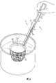
See also shown in Figure 6, the user can be engaged in regulating rack 1 top with conditioning spoon 2, and food materials are placed in the support body 12, hold handle 11 and support body 12 is inserted in the soup to hold, utilize salding soup liquid that food materials in the support body 12 are boiled, and be covered in support body 12 tops by spoon body 22, food materials are unlikely to along with the soup rolling of boiling is scattered; If the food materials in the support body 12 are observed or taken out to user's desire, only need push kettleholder 21 ends of conditioning spoon 2, then this spoonful body 22 is that fulcrum raises up with resisting block 2111, the user can observe or take out food materials easily.Yet, conditioning spoon 2 can also be separated with regulating rack 1, the user can use this conditioning spoon 2 separately, and spoonful end 221 by conditioning spoon 2, dips the soup product and drinks, or uses this regulating rack 1 separately, rinses the usefulness of cooking and food materials are placed in the support body 12.
Utilize conditioning spoon 2 and regulating rack 1 to combine in the foregoing description, designs simplification not only, and still can reach and commonly use structure and coat the advantage that food materials are unlikely to be scattered and; But this conditioning rack delamination conditioning spoon 2 and regulating rack 1, the user can use regulating rack 1 to rinse the material of cooking separately, it is edible to use conditioning spoon 2 to dip the soup product separately, also can use as the conditioning rack in conjunction with both, has more usage compared to the structure of commonly using.If the food materials in the rack are taken out or observed to desire, the user only need push kettleholder 21 ends, spoonful body 22 is raised up get final product, and this spoonful body 22 only starts in support body 12 tops, and the accommodation space in the shared slaughterhouse is less.In addition, the sliding embedding of above-mentioned conditioning rack utilization portion 211 engages with caulking groove 1111 clips of holding part 111, the user only needs cunning embedding portion 211 is inserted in the holding part 111, move down along lever 11 again, can be with the neck 2112 urgent caulking grooves 1111 that enter easily in conjunction with conditioning spoon 2 and regulating rack 1, operation is very easy.
See also another embodiment schematic diagram shown in Figure 7, originally the spoon end 221, replaced to lave net 222, this lave net 222 also has the effect that covers support body 12, and passes through the network structure of lave net 222, and the user can use this conditioning spoon 2 separately and soup stock be pulled out edible.
The above only is preferred embodiment of the present utility model; not in order to restriction the utility model; all any modifications of within spirit of the present utility model and principle, being done; be equal to replacement and improvement etc.; as the spoon body 22 that changes this conditioning spoon 2 has identical covering support body 12 effects for other and can implement according to this; or change support body 12; the structure of lever 11 is for other engraved structure that can implement according to this and have same effect; or the structure that changes this cunning embedding portion 211 can implement according to this for other and have same effect, all should be included within the protection domain of the present utility model.