CN201075432Y - Electric Connector - Google Patents
Electric Connector Download PDFInfo
- Publication number
- CN201075432Y CN201075432Y CNU2007200390188U CN200720039018U CN201075432Y CN 201075432 Y CN201075432 Y CN 201075432Y CN U2007200390188 U CNU2007200390188 U CN U2007200390188U CN 200720039018 U CN200720039018 U CN 200720039018U CN 201075432 Y CN201075432 Y CN 201075432Y
- Authority
- CN
- China
- Prior art keywords
- electrical connector
- curved connection
- conductive terminal
- elastic contact
- curved
- Prior art date
- Legal status (The legal status is an assumption and is not a legal conclusion. Google has not performed a legal analysis and makes no representation as to the accuracy of the status listed.)
- Expired - Fee Related
Links
Images


Landscapes
- Connector Housings Or Holding Contact Members (AREA)
Abstract
一种电连接器(100),其包括设有收容槽(16)的绝缘本体(1)及收容于收容槽的导电端子(2)。导电端子包括沿相反方向弯折的第一、第二弯曲连接部(23,25)、两端分别连接上述两弯曲连接部的臂部(24)、自第一弯曲连接部的自由端延伸形成的固持部(22)及由第二弯曲连接部的自由端倾斜向外延伸形成的弹性接触臂(26)。上述两弯曲连接部均由一直线段(231,251)及位于直线段两端的两圆弧段(232,233,252,253)形成。弯曲连接部的直线段可有效分散应力,防止端子变形。
An electrical connector (100), comprising an insulating body (1) provided with a receiving groove (16) and a conductive terminal (2) accommodated in the receiving groove. The conductive terminal includes first and second curved connection parts (23, 25) bent in opposite directions, arm parts (24) whose two ends are respectively connected to the two curved connection parts, and formed by extending from the free end of the first curved connection part. The retaining portion (22) and the elastic contact arm (26) formed by extending obliquely outward from the free end of the second curved connection portion. The above-mentioned two curved connection parts are both formed by a straight line segment (231, 251) and two circular arc segments (232, 233, 252, 253) located at both ends of the straight line segment. The straight section of the curved connection can effectively disperse stress and prevent terminal deformation.
Description
【技术领域】【Technical field】
本实用新型涉及一种电连接器,尤其涉及一种用于手机或手持装置中与电池电性连接的电连接器。The utility model relates to an electric connector, in particular to an electric connector used in a mobile phone or a hand-held device to be electrically connected with a battery.
【背景技术】【Background technique】
美国专利公告第6,908,341号公开了一种现有电连接器,其包括绝缘本体及收容于绝缘本体内的若干导电端子。导电端子包括突伸出绝缘本体一侧开口的用以对接的接触部、固定于相对于绝缘本体开口侧的另一侧的固定部及连接上述两者的S形弹性部,该弹性部借由两弯曲部弯折成S形以增加其弹性。但是两弯曲部为圆弧状,其在成型过程中弯折处表面容易产生裂纹,在电池频繁插拔时这些裂纹会导致弯曲部断裂。并且电池抵接导电端子时,弯曲部弯曲而产生的应力会集中于一点,这更加导致端子发生永久形变,使电连接器在使用不久后容易发生导通不良或接触不可靠等失效问题。US Patent No. 6,908,341 discloses a conventional electrical connector, which includes an insulating body and a plurality of conductive terminals accommodated in the insulating body. The conductive terminal includes a contact portion protruding from the opening on one side of the insulating body, a fixing portion fixed on the other side opposite to the opening side of the insulating body, and an S-shaped elastic portion connecting the two. The two bending parts are bent into an S shape to increase its elasticity. However, the two curved parts are arc-shaped, and cracks are likely to occur on the surface of the bent parts during the forming process, and these cracks will cause the curved parts to break when the battery is frequently inserted and pulled out. Moreover, when the battery touches the conductive terminal, the stress generated by the bending part will be concentrated at one point, which further leads to permanent deformation of the terminal, making the electrical connector prone to failure problems such as poor conduction or unreliable contact soon after use.
因此,有必要设计一种可克服上述缺陷的电连接器。Therefore, it is necessary to design an electrical connector that can overcome the above defects.
【实用新型内容】【Content of utility model】
本实用新型的目的在于提供一种端子具有弯曲部以增加弹性的电连接器,其端子的弯曲部不易产生裂纹或断裂。The purpose of the utility model is to provide an electrical connector with a terminal having a bent portion to increase elasticity, and the bent portion of the terminal is not easily cracked or broken.
为达到上述目的,本实用新型采用如下技术方案:一种电连接器,其包括设有收容槽的绝缘本体及收容于收容槽的若干导电端子,导电端子包括第一、第二弯曲连接部、两端分别连接第一、第二弯曲连接部的臂部、自第一弯曲连接部的自由端延伸形成的固持部及自第二弯曲连接部的自由端倾斜向外延伸形成的弹性接触臂,且第一、第二弯曲连接部是沿相反方向弯折;其中,第一、第二弯曲连接部均由一直线段及位于直线段两端的两圆弧段形成。In order to achieve the above object, the utility model adopts the following technical solutions: an electrical connector, which includes an insulating body provided with a receiving groove and a plurality of conductive terminals accommodated in the receiving groove, the conductive terminals include first and second curved connection parts, The two ends are respectively connected to the arms of the first and second curved connection parts, the holding part extending from the free end of the first curved connection part, and the elastic contact arm formed by extending obliquely outward from the free end of the second curved connection part, And the first and second curved connection parts are bent in opposite directions; wherein, the first and second curved connection parts are both formed by a straight line segment and two arc segments located at two ends of the straight line segment.
与现有技术相比,本实用新型电连接器具有如下有益效果:弯曲连接部的直线段可有效分散应力,防止端子变形。Compared with the prior art, the electrical connector of the utility model has the following beneficial effects: the straight section of the curved connection part can effectively disperse stress and prevent terminal deformation.
【附图说明】【Description of drawings】
图1是本实用新型电连接器的立体组合图。Fig. 1 is a three-dimensional assembled view of the electrical connector of the present invention.
图2是图1所示另一角度的立体组合图。Fig. 2 is a three-dimensional assembled view from another angle shown in Fig. 1 .
图3是图1所示电连接器的立体分解图。FIG. 3 is an exploded perspective view of the electrical connector shown in FIG. 1 .
图4是电连接器端子的立体图。Fig. 4 is a perspective view of an electrical connector terminal.
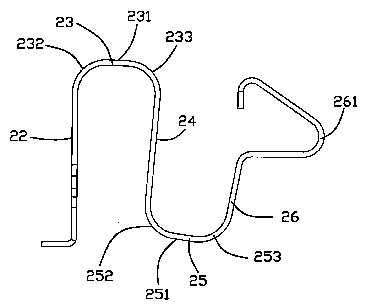
图5是图4所示端子的主视图。Fig. 5 is a front view of the terminal shown in Fig. 4 .
【具体实施方式】【Detailed ways】
请参阅图1、2所示,电连接器100包括绝缘本体1及收容于绝缘本体1的若干导电端子2。Referring to FIGS. 1 and 2 , the
请参阅图2、3所示,绝缘本体1呈矩形设置,其设有安装面11、与安装面11相对设置的顶壁12、对接面13、与对接面12相对设置的后壁14及垂直于安装面11与对接面13的两侧壁15,若干并列设置的收容槽16贯通安装面11与对接面13,且于靠近对接面处形成挡块161,后壁14于靠近安装面11处开设有凹槽141。绝缘本体1的两侧壁15上分别设有安装部17,该安装部17上开设有卡持槽171,固持件(未图示)一端固定于卡持槽171内,另一端固定于电连接器100将要安装的物件上,从而将电连接器100固定于该物件上。Please refer to Fig. 2, shown in 3,
请参阅图4、5所示,导电端子2是由一金属片弯折形成,其收容于绝缘本体1的收容槽16中。导电端子2包括固持部22、与固持部22呈一定夹角设置的臂部24、与臂部24呈一定夹角设置的弹性接触臂26、光滑连接固持部22与臂部24一端的第一弯曲连接部23及光滑连接臂部24另一端与弹性接触臂26的第二弯曲连接部25,即臂部24两端分别光滑连接沿相反方向弯折的第一、第二弯曲连接部23、25,固持部22是从第一弯曲连接部23的自由端延伸形成,弹性接触臂26是由第二弯曲连接部25的自由端倾斜向外延伸形成。固持部22两侧边上设有两对凸刺221,以将导电端子2稳固地固持于绝缘本体1中,其自由端延伸出可焊接于电路板的尾部21。弹性接触臂26沿大致垂直于固持部22的方向向外弯折形成山型接触部261,其末端朝向臂部24,且末端设有向下弯折设置的卡持部262,卡持部262的横向设有一对凸块263,以防止弹性接触臂26的末端露出于绝缘本体1,加强对导电端子2的固定。Please refer to FIGS. 4 and 5 , the
第一弯曲连接部23包括水平的第一直线段231及自第一直线段231两端同向弯折的第一、第二圆弧段232、233,即第一圆弧段232光滑连接固持部22与第一直线段231的左端,第二圆弧段233光滑连接第一直线段231右端与臂部24的上端。第二弯曲连接部25与第一弯曲连接部23的结构类似,其同向弯折的第三、第四圆弧段252、253分别光滑连接臂部24的下端与第二直线段251的左端及第二直线段251的右端与弹性接触臂26的下端。The first
导电端子2自绝缘本体1的安装面11组装进入,其固持部22借凸刺221固定于后壁14的狭槽142(参图2所示)内,第一、第二弯曲连接部23、25、臂部24及弹性接触臂26收容于收容槽16内,接触部261凸露于绝缘本体1的对接面13,凸块263抵挡于挡块161而将卡持部262卡持于收容槽16内,尾部21自后壁14开设的凹槽141(参图2所示)延伸出来。The
对接元件(如电池等)在抵压接触部261时,弹性接触臂26与臂部24之间的夹角及臂部24与固持部22之间的夹角均会发生变化,从而在第一、第二弯曲连接部23、25处产生应力。现有技术中弯曲连接部仅为一圆弧设置,应力会集中于圆弧状弯曲连接部的中心处,受力范围较小,容易使端子产生永久形变,而本实用新型中第一、第二弯曲连接部23、25分别具有第一、第二直线段231、251,弯曲连接部产生的应力是作用于第一、第二直线段231、251上,应力承受的范围增大,可有效分散应力,进而达到防止端子永久变形的目的。且弯曲连接部的直线段231、251还能避免端子成型时在弯曲表面产生裂纹,能有效延长产品之使用寿命。When the docking element (such as a battery, etc.) presses the
本实用新型不局限于上述实施方式,如电连接器100的导电端子2也可由一弯曲连接部光滑连接固持部22与弹性接触臂26而形成,此处不再一一赘述。The present invention is not limited to the above embodiments. For example, the
Claims (10)
Priority Applications (1)
| Application Number | Priority Date | Filing Date | Title |
|---|---|---|---|
| CNU2007200390188U CN201075432Y (en) | 2007-06-27 | 2007-06-27 | Electric Connector |
Applications Claiming Priority (1)
| Application Number | Priority Date | Filing Date | Title |
|---|---|---|---|
| CNU2007200390188U CN201075432Y (en) | 2007-06-27 | 2007-06-27 | Electric Connector |
Publications (1)
| Publication Number | Publication Date |
|---|---|
| CN201075432Y true CN201075432Y (en) | 2008-06-18 |
Family
ID=39520689
Family Applications (1)
| Application Number | Title | Priority Date | Filing Date |
|---|---|---|---|
| CNU2007200390188U Expired - Fee Related CN201075432Y (en) | 2007-06-27 | 2007-06-27 | Electric Connector |
Country Status (1)
| Country | Link |
|---|---|
| CN (1) | CN201075432Y (en) |
Cited By (3)
| Publication number | Priority date | Publication date | Assignee | Title |
|---|---|---|---|---|
| CN109586069A (en) * | 2017-09-28 | 2019-04-05 | 格棱电子科技(赣州)有限公司 | Floatation style connector and its conductive terminal |
| CN115395263A (en) * | 2022-08-12 | 2022-11-25 | 鸿日达科技股份有限公司 | FPC connector and terminal thereof |
| WO2025092120A1 (en) * | 2023-10-30 | 2025-05-08 | 深圳市信维通信股份有限公司 | Elastic piece connector and electronic device |
-
2007
- 2007-06-27 CN CNU2007200390188U patent/CN201075432Y/en not_active Expired - Fee Related
Cited By (4)
| Publication number | Priority date | Publication date | Assignee | Title |
|---|---|---|---|---|
| CN109586069A (en) * | 2017-09-28 | 2019-04-05 | 格棱电子科技(赣州)有限公司 | Floatation style connector and its conductive terminal |
| CN109586069B (en) * | 2017-09-28 | 2023-12-05 | 格棱电子科技(赣州)有限公司 | Floating connector and conductive terminal thereof |
| CN115395263A (en) * | 2022-08-12 | 2022-11-25 | 鸿日达科技股份有限公司 | FPC connector and terminal thereof |
| WO2025092120A1 (en) * | 2023-10-30 | 2025-05-08 | 深圳市信维通信股份有限公司 | Elastic piece connector and electronic device |
Similar Documents
| Publication | Publication Date | Title |
|---|---|---|
| CN203056159U (en) | card edge connector | |
| CN201797115U (en) | Electrical connectors and their conductive terminals | |
| TW201014063A (en) | Electrical connector | |
| CN201515054U (en) | Board terminal electric connector | |
| CN201549679U (en) | Electric connector | |
| CN201323260Y (en) | Card connector | |
| CN201075432Y (en) | Electric Connector | |
| CN105281120B (en) | Battery connector | |
| CN205319424U (en) | battery connector | |
| CN219498398U (en) | Electric connector | |
| CN201549668U (en) | Terminal and electrical connector using the terminal | |
| CN101677154B (en) | Electric connector | |
| CN201160138Y (en) | Electrical Connector Assembly | |
| CN205385130U (en) | Conductive terminal , connector and electronic equipment | |
| CN201285841Y (en) | Electric connector | |
| CN200941463Y (en) | battery connector | |
| CN203466318U (en) | Micro-usb connector | |
| CN201430279Y (en) | Electric connector | |
| CN101136524A (en) | Electrical connector and manufacturing method thereof | |
| CN201113028Y (en) | electrical connector | |
| CN201285939Y (en) | Electric connector | |
| CN201639017U (en) | Electric connector terminal | |
| CN202142682U (en) | Battery connector | |
| CN217239793U (en) | a connector terminal | |
| CN201160135Y (en) | Electrical Connector Assembly |
Legal Events
| Date | Code | Title | Description |
|---|---|---|---|
| C14 | Grant of patent or utility model | ||
| GR01 | Patent grant | ||
| C17 | Cessation of patent right | ||
| CF01 | Termination of patent right due to non-payment of annual fee |
Granted publication date: 20080618 Termination date: 20110627 |