CN201123780Y - Vacuum cleaner - Google Patents
Vacuum cleaner Download PDFInfo
- Publication number
- CN201123780Y CN201123780Y CNU2007201866172U CN200720186617U CN201123780Y CN 201123780 Y CN201123780 Y CN 201123780Y CN U2007201866172 U CNU2007201866172 U CN U2007201866172U CN 200720186617 U CN200720186617 U CN 200720186617U CN 201123780 Y CN201123780 Y CN 201123780Y
- Authority
- CN
- China
- Prior art keywords
- vacuum cleaner
- air
- housing
- filter
- dish
- Prior art date
- Legal status (The legal status is an assumption and is not a legal conclusion. Google has not performed a legal analysis and makes no representation as to the accuracy of the status listed.)
- Expired - Fee Related
Links
- 239000011148 porous material Substances 0.000 claims description 25
- 238000003780 insertion Methods 0.000 claims description 8
- 230000037431 insertion Effects 0.000 claims description 8
- 239000000428 dust Substances 0.000 abstract 3
- 230000000712 assembly Effects 0.000 description 31
- 238000000429 assembly Methods 0.000 description 31
- 239000000463 material Substances 0.000 description 8
- 238000004140 cleaning Methods 0.000 description 5
- 238000007789 sealing Methods 0.000 description 5
- 238000001914 filtration Methods 0.000 description 3
- 239000004033 plastic Substances 0.000 description 3
- 229920003023 plastic Polymers 0.000 description 3
- 238000010276 construction Methods 0.000 description 2
- 229920001971 elastomer Polymers 0.000 description 2
- 239000012530 fluid Substances 0.000 description 2
- 230000002950 deficient Effects 0.000 description 1
- 239000000806 elastomer Substances 0.000 description 1
- 238000005516 engineering process Methods 0.000 description 1
- 230000008676 import Effects 0.000 description 1
- 238000012423 maintenance Methods 0.000 description 1
- 239000012858 resilient material Substances 0.000 description 1
- 230000002195 synergetic effect Effects 0.000 description 1
Images




Landscapes
- Filters For Electric Vacuum Cleaners (AREA)
Abstract
The utility model discloses a vacuum dust collector, comprising a housing, a vacuum pressure source and a detachable filter coil, wherein, the housing limits an air suction inlet hole and a chipping cavity communicated with the air suction inlet hole; the vacuum pressure source is arranged inside the housing and is used for providing vacuum pressure for the air suction inlet hole; the detachable filter coil can be contacted from the outside of the housing and is arranged in an air stream path between the air suction inlet hole and the vacuum pressure source, the housing comprises a basic container part for limiting the chipping cavity and a head part which can be detachably fixed on the base container part, the detachable filter coil can be received in a hole inside the head part along the inserting direction with an angle relative to the horizontal line. A user can contact the filter without disconnecting the vacuum dust collector and change or clean the filter as well as place the filter to the original position without disconnecting the vacuum dust collector.
Description
Technical field
The utility model relates to vacuum cleaner, more particularly, relate to vacuum cleaner filter (vacuum filter), relate in particular to a kind of vacuum cleaner with flat-panel filter, this flat-panel filter is detachably in the outside of vacuum cleaner, and therefore need not take vacuum cleaner apart just can clean and change the filter flat board easily.
It is No.60/859 that the application requires to enjoy in the application number of submitting on November 20th, 2006,944 U.S. Provisional Application No..The disclosed content of above-mentioned application is incorporated among the application as a reference.
Background technology
Statement to this part only provides the background information that relates to the utility model disclosure, does not constitute prior art.
Vacuum cleaner, especially industrial station-service vacuum cleaner (shop vacuum) can be equipped with the filter unit of the entry that directly is connected to Floor nozzle of duster (vacuum head), and Floor nozzle of duster is connected with vacuum source.In order to touch this vacuum filter, must unload Floor nozzle of duster from container.Then, must or unload vacuum filter or it is cleaned, simultaneously vacuum filter is installed on the Floor nozzle of duster reliably.Cleaning and/or dismounting filter not only bother but also dirty.
The utility model content
The purpose of this utility model is to provide a kind of defective that can overcome prior art, has the vacuum cleaner of flat-panel filter.The vacuum cleaner that the utility model provides comprises: housing, and it limits and air-breathingly enters oral pore and enter the chip chamber that oral pore is communicated with air-breathing; Vacuum pressure source, it is set in the housing, and being used for provides vacuum pressure to the air-breathing oral pore that enters; The removable filter device dish that can touch from the outside of housing, this detachable filter dish is set in the air-breathing air flow path that enters between oral pore and the vacuum pressure source, housing comprises basic container part that limits the chip chamber and the head part that is detachably fixed to basic container part, removable filter device dish is inserted in the interior hole of head part, and removable filter device dish is housed inside the edge with respect in the hole in the head part of horizontal line direction of insertion at angle.
According on the other hand of the present utility model, a kind of vacuum cleaner is provided, comprising: housing, it limits and air-breathingly enters oral pore and enter the chip chamber that oral pore is communicated with air-breathing; Motor and by the impeller of the drive shaft of motor, motor and impeller are set in the housing, and being used for provides vacuum pressure to the air-breathing oral pore that enters, and driving shaft can be around the axis rotation that becomes 10 to 30 degree angles with vertical line.
According to another aspect of the present utility model, a kind of vacuum cleaner is provided, comprising: housing, it limits and air-breathingly enters oral pore and enter the chip chamber that oral pore is communicated with air-breathing; One motor and by the impeller of the drive shaft of this motor, motor and impeller are placed in the housing, and being used for provides vacuum pressure to the air-breathing oral pore that enters, and driving shaft can be around the axis rotation that becomes 10 to 30 degree angles with vertical line; And be arranged at a removable filter device in the air-breathing air flow path that enters between oral pore and the vacuum pressure source.
According to other aspects of the present utility model, removable filter device dish comprises the dish framework, and this dish framework has the handle that can touch from the outside of housing.This vacuum cleaner also comprises the filter insert that is contained in the removable filter device dish, the angle of direction of insertion with respect to horizontal line between 10 the degree and 30 the degree between.Described head part comprises the guiding channel that extends from the hole that is used to hold removable filter device dish, and this guiding channel extends to described basic container part with an angle.Guiding channel comprises inclined surface, so that make removable filter device dish compress impeller eye, thereby provides being tightly connected between interior filter insert of removable filter device dish and the impeller eye.Vacuum pressure source comprises motor and by the impeller of the drive shaft of motor, and driving shaft is usually perpendicular to the direction of insertion of guiding channel.In addition, the hole sealed engagement in dish framework and the described housing.
By means of the utility model, the user needn't take vacuum cleaner apart just can touch filter, needn't take then that vacuum cleaner can be changed apart or cleaning and filtering and easily filter being replaced.
By the following description further scope of application of the present utility model will be more obvious.It should be understood that these are described and instantiation only is used for explanation and is not used in the scope of the present utility model that limits.
Description of drawings
Hereinafter the description of accompanying drawing only is used for explanation, rather than by any way to the restriction of scope disclosed in the utility model.
Fig. 1 is the schematic cross-section according to the station-service vacuum cleaner of the utility model principle;
Fig. 2 is the perspective view according to the detachable filter dish of the utility model principle;
The part of Fig. 3 (cut away) perspective view shows according to the detachable filter dish of the station-service vacuum cleaner of the utility model principle and maintenance oralia;
Partial cross section's perspective view of Fig. 4 illustrates the dismantled and assembled property according to the filter discs of the utility model principle;
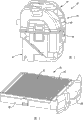
Fig. 5 is the perspective view according to the station-service vacuum cleaner that is combined with the detachable filter dish of the utility model principle;
Fig. 6 is the perspective view according to the detachable filter dish of the utility model principle;
The perspective view of Fig. 7 shows the filter that removes from the detachable filter dish according to the utility model principle and inserts box;
Fig. 8 is the perspective view of Floor nozzle of duster, and it shows the insertion angle according to the detachable filter dish of the utility model principle;
The cross-sectional view of Fig. 9 has illustrated according to the utility model principle and has been contained in detachable filter dish in the Floor nozzle of duster, also shows the angled orientation of motor and vacuum cleaner impeller;
The cross-section details of Figure 10 illustrates according to the filter discs of the utility model principle and the sealing relationship between the vaccum case;
The cross-section details of Figure 11 illustrates according to the innermost part of the detachable filter dish of the utility model principle and the sealing relationship of vaccum case.
The specific embodiment
It in fact only is exemplary below describing, and is not the restriction to present disclosure, the application or the scope of application.It should be understood that in whole accompanying drawings corresponding Reference numeral representation class like or corresponding parts and structure division (feature).
The exemplary vacuum cleaner 10 of foundation principle of the present utility model is described referring now to Fig. 1-4.Vacuum cleaner 10 can comprise the Floor nozzle of duster 14 of container 12 and closed container 12.Floor nozzle of duster can support drive motor 16.Drive motors 16 can support the induced-draught fan 18 in the fan house 20 (fan chamber) that can be arranged at Floor nozzle of duster 14.Fan house 20 can be communicated with outlet 22 and inlet 24 fluids.Inlet 24 can be covered by the filter assemblies 26 of the filter housings 28 that is positioned at Floor nozzle of duster 14.Filter housings 28 can comprise inclined-plane 30, this inclined-plane can cause filter assemblies 26 towards inlet 24 opening and with this opening sealed engagement.
When connecting power supply, motor 16 can make induced-draught fan 18 rotations, thereby enters oral pore 31 with the air suction is air-breathing, and makes air flow through container 12, filter assemblies 26, inlet 24 to enter fan house 20.Induced-draught fan 18 can promote air in the fan house 20 to be made it by exporting 22 and discharge vacuum cleaner 10.Flexible pipe 32 can be connected to and enter oral pore 31.
With reference to figure 2, filter assemblies 26 can comprise the framework 36 of support plate filter 38.In embodiment of the present disclosure, flat-panel filter 38 can be the corrugated paper filter.In some alternative embodiment, flat-panel filter 38 can be made by many and alternative material commonly known in the art.Flat-panel filter 38 can comprise and deviates from inlet 24 input side and towards the outlet side of inlet 24.
As shown in the figure, framework 36 can comprise handle 40.In this embodiment, framework 36 and handle 40 can be the individual constructions of an integral body.In some alternative embodiment, framework 36 can be separate and the different parts that fit together with handle 40.Framework 36 can be made by the material with enough rigidity, allowing the user to catch handle 40 and to shake and/or knock filter assemblies 26, thus cleaning and filtering 38.Framework 36 can be made by plastic material and/or many with different alternative material commonly known in the art.
In illustrated embodiment, filter assemblies 26 can be square shape, and perhaps, in some alternative embodiment, filter assemblies 26 can have any geometry that inlet 24 was crossed and covered in extension.In addition, in illustrated embodiment, filter assemblies 26 can have the profile of flat (or smooth).In some alternative embodiment, filter assemblies 26 can have many with different profiles.Only as an example, filter assemblies 26 can have the concave arc surface (concave profile) towards the vessel side of filter assemblies 26.By this way, can increase effective cleaning area of flat-panel filter 26.Can be by being installed in the door 42 contacted filter assemblies 26 on container 12 or the Floor nozzle of duster 14.In the present embodiment, the bottom side hinge of door 42 can be attached to container 12.Door 42 top side and container 12 can comprise traditional structure division, for example breech lock and/or synergistic rib, and their synergies are temporarily fixed on closed condition with door 42.In some alternative embodiment, the another side rather than the base hinge of door 42 can be attached to container 12.For example, a side hinge of door 42 can be attached to container 12, so that can open the opposite flank of door 42 pivotally.In some alternative embodiment, door 42 can be slidably mounted in the relative groove that is arranged in the container 12 and not use any hinge to connect.
With reference to figure 4, can place pad 44 between container 12 and the door 42 to improve gas sealing ability.As shown in the figure, pad 44 can be installed on the container 12.Perhaps, pad 44 can be installed on the door 42.Door 42 can comprise saddle 46, and this saddle and handle 40 interact with raising filter assemblies 26 and the gas sealing ability between 24 of entering the mouth.For example, when being in half-open position, saddle 46 can be near handle 40 at as shown in Figure 4 door 42.When door 42 was moved to as shown in Figure 3 closed condition, saddle 46 can laterally push filter assemblies 26 in the filter housings 28 of Floor nozzle of duster 14.Because door 42 arcuate movement track, saddle 46 also can upwards push away filter assemblies 26 and against inlet 24.
The user will not pull down the just contacted filter assembly 26 of energy from container 12 by Floor nozzle of duster 14.For example, the user can open door 42, catches handle 40, and filter assemblies 26 is pulled out filter housings 28.Then, filter assemblies 26 can be shaken and/or knock to the user to remove chip on the flat-panel filter 38 or the filter 38 that more renews.In addition, the filter assemblies 26 of little profile (low profile) can increase the carrying capacity of container 12.
Second example of vacuum cleaner 60 described below with reference to Fig. 5-11.Vacuum cleaner 60 comprises the Floor nozzle of duster 64 of container 62 and closing containers 62.As shown in Figure 9, Floor nozzle of duster 64 can support drive motor 66.Drive motors 66 can prop up the induced-draught fan 68 in the fan house 70 that stays at Floor nozzle of duster 64.Fan house 70 can be communicated with outlet 72 and inlet 74 fluids.Inlet 74 can be covered by the filter assemblies 76 of the filter housings 78 that is positioned at Floor nozzle of duster 64.Filter housings 78 can comprise inclined-plane 80, and this inclined-plane can cause filter assemblies 76 to engage towards the opening of inlet 74 and with this opening.Specifically, as shown in figure 11, the inclined-plane 80 that is arranged on the inner surface of filter housings 78 guides filter assemblies 76 in the upward direction, cause the continuous pad 82 that is provided with around this filter periphery to engage, be tightly connected thereby between filter assemblies 76 and ingate 74, provide with ingate 74 fin 84 on every side.Pad 82 shown in Figure 10 also engages with the fin 84 of the proximal end of filter assemblies 76.
When connecting power supply, motor 66 can make induced-draught fan 68 rotations, enters container 62 thereby make air flow through air-breathing inlet 85, again from container 62 by filter assemblies 76,74 go forward side by side into fan house 70 by entering the mouth.The air that induced-draught fan 68 can promote in the fan house 70 is discharged vacuum cleaner 60 by outlet 72.
With reference to figure 6 and 7, filter assemblies 76 can comprise the framework 90 of support plate filter 92.In the disclosed embodiment, flat-panel filter 92 can be the corrugated paper filter, and it has around the plastics of this corrugated paper filter, elastomer or rubber frame part 96.Frame part 96 can comprise the recess 97 that is in wherein, and this recess will fill up 82 and be contained in wherein.Perhaps, in order to reduce optional feature, pad 82 and frame part 96 can form as one.In this case, in order to strengthen filling up and can forming with soft resilient material the filter frame and the pad of combination around the sealed engagement between the projection 84 of entry 74.In some alternative embodiment, flat-panel filter 92 can be made by many and alternative material commonly known in the art.Flat-panel filter 92 can comprise and deviates from inlet 74 input side 92a and towards the outlet side 92b of inlet 74.
As shown in the figure, dish framework 90 can comprise handle 100.In this exemplary embodiment, framework 90 and handle 100 can be the individual constructions of an integral body.In some alternative embodiment, framework 90 can be separating and different assemblies of being assembled together with handle 100.Framework 90 can be made allowing the user to catch handle 100 and to shake and/or knock filter assemblies 76 by having the enough materials of rigidity, thus cleaning and filtering 92.Framework 90 can be made by plastic material and/or many and different alternative material commonly known in the art.
In this illustrated embodiment, filter assemblies 76 has rectangular shape.Certainly, filter assemblies 76 can have any geometry that inlet 74 was crossed and covered in extension.
As shown in Figure 5, can contacted filter 76 by the handle 100 that is exposed to vacuum cleaner 60 outsides.Filter assemblies 76 is received in as shown in Figure 8 the filter housings 78 slidably.As shown in Figure 8, it is the angle [alpha] of 10 to 45 degree that direction of insertion that can detachable filter dish 76 is set to respect to its horizontal angle
1Therefore, the filter housings 78 of Floor nozzle of duster 64 can extend downwardly into the inner end of container 62 to filter housings.So, as shown in Figure 9, the angular orientation of filter discs assembly 76 can be become make that driving shaft 67 that motor 66 and induced-draught fan 68 be orientated motor 66 is α with respect to the angle of vertical line
2Angle α
2Can become with respect to vertical line between 10 to 45 degree, perhaps if preferably talk about, with vertical line out-of-line (out of line).Although angle α
1And α
2Each other also can be different, but they also can be identical or basic identical.The described angular orientation of filter discs assembly 76, motor 66 and induced-draught fan 68 can make the vertically whole stack height of motor, fan and filter reduce, so that the whole height minimum of vacuum cleaner 60.In addition, as shown in Figure 9, the described angular orientation of filter assemblies 76 can be orientated filter air-breathing inlet 85 with container 62 more near straight line.With reference to Figure 10, what be worth to remind is, filter housings 78 can be provided with fin 106, and the respective ribs 108 that is provided with on the surface of this fin and dish 90 is chimeric.Fin 106 and 108 is chimeric each other, is fixed in the filter housings 78 so that will coil 90.Rib 106,108 can be the user sense of touch indication is provided, and makes them know that dish 90 is inserted in the filter housings 78 rightly.Also additional sealing strip 110 can be set, be used for engaging hermetically handle portion near the dish of the opening that imports filter housings 78.This being tightly connected can prevent that air is inhaled into vacuum cleaner around the opening of dish housing, and the vacuum pressure that therefore can eliminate the noise of not expecting and avoid being used to drawing chip reduces.
Claims (14)
1, a kind of vacuum cleaner is characterized in that, comprising:
One housing, it limits and air-breathingly enters oral pore and air-breathingly enter the chip chamber that oral pore is communicated with this;
One vacuum pressure source, it is set in the described housing, and being used for provides vacuum pressure to the described air-breathing oral pore that enters;
Can touch and be set at a detachable filter dish the described air-breathing air flow path that enters between oral pore and the described vacuum pressure source from described hull outside, wherein said housing comprises basic container part that limits described chip chamber and the head part that is detachably fixed to described basic container part, described removable filter device dish is inserted in the interior hole of described head part, and described removable filter device dish is housed inside the edge with respect in the described hole in the described head part of horizontal line direction of insertion at angle.
2, vacuum cleaner according to claim 1 is characterized in that, described removable filter device dish comprises the dish framework, and this dish framework has the handle that can touch from the outside of described housing.
3, vacuum cleaner according to claim 1 is characterized in that, also comprises the filter insert that is contained in the described removable filter device dish.
4, vacuum cleaner according to claim 1 is characterized in that, the angle of described direction of insertion with respect to horizontal line between 10 the degree and 30 the degree between.
5, vacuum cleaner according to claim 1 is characterized in that, described head part comprises the guiding channel that extends from the described hole that is used to hold described removable filter device dish.
6, vacuum cleaner according to claim 5 is characterized in that, described guiding channel extends to described basic container part with an angle.
7, vacuum cleaner according to claim 6, it is characterized in that, described guiding channel comprises inclined surface, so that make described removable filter device dish compress impeller eye, thereby provide being tightly connected between interior filter insert of described removable filter device dish and the described impeller eye.
8, vacuum cleaner according to claim 7 is characterized in that, described vacuum pressure source comprises motor and by the impeller of the drive shaft of described motor, and described driving shaft is usually perpendicular to the direction of insertion of described guiding channel.
9, vacuum cleaner according to claim 2 is characterized in that, the hole sealed engagement in described dish framework and the described housing.
10, a kind of vacuum cleaner is characterized in that, comprising:
One housing, it limits and air-breathingly enters oral pore and air-breathingly enter the chip chamber that oral pore is communicated with this;
One motor and by the impeller of the drive shaft of this motor, this motor and described impeller are set in the described housing, be used for providing vacuum pressure to the described air-breathing oral pore that enters, described driving shaft can be around the axis rotation that becomes 10 to 30 degree angles with vertical line.
11, vacuum cleaner according to claim 10 is characterized in that, also comprises the removable filter device that is placed in the described air-breathing air flow path that enters between oral pore and the described vacuum pressure source.
12, vacuum cleaner according to claim 11, it is characterized in that, described filter comprises upper face and is in substantially parallel relationship to the lower surface of described upper face that the residing plane of each of the surface, described upper and lower of described filter cardinal principle is perpendicular to the described axis of described driving shaft.
13, vacuum cleaner according to claim 12 is characterized in that, described filter comprises the dish framework, and this dish framework has the handle that can touch from the outside of described housing.
14, a kind of vacuum cleaner is characterized in that, comprising:
One housing, its limit air-breathing enter oral pore and with the described air-breathing chip chamber that oral pore is communicated with that enters;
One motor and by the impeller of the drive shaft of described motor, described motor and described impeller are placed in the described housing, be used for providing vacuum pressure to the described air-breathing oral pore that enters, described driving shaft can be around the axis rotation that becomes 10 to 30 degree angles with vertical line;
Be arranged at the removable filter device in the described air-breathing air flow path that enters between oral pore and the described vacuum pressure source.
Applications Claiming Priority (3)
| Application Number | Priority Date | Filing Date | Title |
|---|---|---|---|
| US85994406P | 2006-11-20 | 2006-11-20 | |
| US60/859,944 | 2006-11-20 | ||
| US11/870,822 | 2007-10-11 |
Publications (1)
| Publication Number | Publication Date |
|---|---|
| CN201123780Y true CN201123780Y (en) | 2008-10-01 |
Family
ID=39997197
Family Applications (1)
| Application Number | Title | Priority Date | Filing Date |
|---|---|---|---|
| CNU2007201866172U Expired - Fee Related CN201123780Y (en) | 2006-11-20 | 2007-11-20 | Vacuum cleaner |
Country Status (1)
| Country | Link |
|---|---|
| CN (1) | CN201123780Y (en) |
Cited By (4)
| Publication number | Priority date | Publication date | Assignee | Title |
|---|---|---|---|---|
| CN103702600A (en) * | 2011-07-25 | 2014-04-02 | 阿尔弗雷德·凯驰两合公司 | Suction apparatus |
| CN104508208A (en) * | 2012-08-01 | 2015-04-08 | 阿尔弗雷德·凯驰两合公司 | Self-propelled floor cleaning machine and a filter system module |
| CN107877363A (en) * | 2016-09-29 | 2018-04-06 | 波音公司 | It is ground cabin assembly and the method for being ground workpiece |
| CN111263606A (en) * | 2017-12-15 | 2020-06-09 | 喜利得股份公司 | filter box |
-
2007
- 2007-11-20 CN CNU2007201866172U patent/CN201123780Y/en not_active Expired - Fee Related
Cited By (8)
| Publication number | Priority date | Publication date | Assignee | Title |
|---|---|---|---|---|
| CN103702600A (en) * | 2011-07-25 | 2014-04-02 | 阿尔弗雷德·凯驰两合公司 | Suction apparatus |
| CN103702600B (en) * | 2011-07-25 | 2017-02-15 | 阿尔弗雷德·凯驰两合公司 | Suction apparatus |
| CN104508208A (en) * | 2012-08-01 | 2015-04-08 | 阿尔弗雷德·凯驰两合公司 | Self-propelled floor cleaning machine and a filter system module |
| CN107877363A (en) * | 2016-09-29 | 2018-04-06 | 波音公司 | It is ground cabin assembly and the method for being ground workpiece |
| CN107877363B (en) * | 2016-09-29 | 2021-06-01 | 波音公司 | Grinding chamber assembly and method for grinding a workpiece |
| CN111263606A (en) * | 2017-12-15 | 2020-06-09 | 喜利得股份公司 | filter box |
| CN111263606B (en) * | 2017-12-15 | 2021-06-15 | 喜利得股份公司 | filter box |
| US12414662B2 (en) | 2017-12-15 | 2025-09-16 | Hilti Aktiengesellschaft | Filter cassette |
Similar Documents
| Publication | Publication Date | Title |
|---|---|---|
| EP1674017B1 (en) | Dust collection unit and vacuum cleaner with the same | |
| EP1922970B1 (en) | Vacuum cleaner with panel filter | |
| CA2730632C (en) | Seal construction for a surface cleaning apparatus | |
| CN1263417C (en) | Locking apparatus of dust-collecting tank for vacuum dust catcher | |
| US20070039127A1 (en) | Dust container of upright type vacuum cleaner and supporting structure for cover thereof | |
| CN201123780Y (en) | Vacuum cleaner | |
| CN1355679A (en) | Vacuum cleaner | |
| KR100730944B1 (en) | Exhaust flow path structure of vacuum cleaner | |
| AU2006249267B8 (en) | Vacuum cleaner | |
| CN220192934U (en) | Handheld assembly and cleaning device | |
| CN208524741U (en) | a surface cleaner | |
| CN207384195U (en) | vacuum cleaner | |
| CN213030578U (en) | Multi-fan dust collector | |
| CN103908194B (en) | Bedding cleaner | |
| CN201691850U (en) | Dust collector | |
| CN219982801U (en) | Dust collecting station | |
| CN222510375U (en) | Sewage tank and cleaning device | |
| CN222646356U (en) | Vacuum sealer with external water collection box | |
| CN210095636U (en) | Dust collection box and cleaning robot with leak-proof design | |
| JP4269315B2 (en) | Electric vacuum cleaner | |
| KR100692552B1 (en) | Dust bucket of vacuum cleaner | |
| KR100635150B1 (en) | Dust collector structure of upright vacuum cleaner | |
| KR200144892Y1 (en) | Vacuum cleaner | |
| CN101147660A (en) | Vacuum cleaner dust-collecting bucket bottom dust removing device | |
| KR100635151B1 (en) | Dust collector cover support structure of upright vacuum cleaner |
Legal Events
| Date | Code | Title | Description |
|---|---|---|---|
| C14 | Grant of patent or utility model | ||
| GR01 | Patent grant | ||
| CF01 | Termination of patent right due to non-payment of annual fee | ||
| CF01 | Termination of patent right due to non-payment of annual fee |
Granted publication date: 20081001 Termination date: 20161120 |