CN201151663Y - Actuating mechanism of automatic oil dispenser - Google Patents
Actuating mechanism of automatic oil dispenser Download PDFInfo
- Publication number
- CN201151663Y CN201151663Y CNU2008200974827U CN200820097482U CN201151663Y CN 201151663 Y CN201151663 Y CN 201151663Y CN U2008200974827 U CNU2008200974827 U CN U2008200974827U CN 200820097482 U CN200820097482 U CN 200820097482U CN 201151663 Y CN201151663 Y CN 201151663Y
- Authority
- CN
- China
- Prior art keywords
- cylinder
- piston rod
- piston
- fuel
- ground
- Prior art date
- Legal status (The legal status is an assumption and is not a legal conclusion. Google has not performed a legal analysis and makes no representation as to the accuracy of the status listed.)
- Expired - Fee Related
Links
Images
Landscapes
- Automatic Assembly (AREA)
Abstract
本实用新型涉及一种自动加油机的执行机构,其特征在于:带有活塞的第一气缸的缸体(11)固定于支座(4)上并与地面垂直,与地面平行的带有活塞的第二气缸与第一气缸活塞杆(12)上端连接,第二气缸的活塞杆(22)的一端与带导向孔的导向柱(5)连接,第三气缸的活塞杆(31)一端穿过导向柱孔与导向柱滑动配合,加油枪(6)与第三气缸的活塞杆一端的端部连接。本实用新型利于节约生产成本,并且有操作方便的优点。
The utility model relates to an executive mechanism of an automatic fuel dispenser, which is characterized in that: a cylinder body (11) of a first cylinder with a piston is fixed on a support (4) and is perpendicular to the ground, and a cylinder body (11) with a piston parallel to the ground The second cylinder of the first cylinder is connected with the upper end of the piston rod (12) of the first cylinder, and one end of the piston rod (22) of the second cylinder is connected with the guide column (5) with a guide hole, and one end of the piston rod (31) of the third cylinder passes through Slidingly fit with the guide post through the guide post hole, and the refueling gun (6) is connected with the end of one end of the piston rod of the third cylinder. The utility model is beneficial to saving production cost and has the advantages of convenient operation.
Description
技术领域 technical field
本实用新型涉及一种自动加油机,特别涉及一种对发动机加注燃油的自动加油机的执行机构。The utility model relates to an automatic fuel dispenser, in particular to an executive mechanism of the automatic fuel dispenser for fueling the engine.
背景技术 Background technique
机动车辆的发动机在出厂装配前会注入一定量的燃油,便于进行调试。目前发动机的燃油加注大多是采用人工操作来完成,即当发动机通过流水线到位后,由操作工人手持加油枪,将机油加入到发动机中,这种加注方式中需要固定1~2个操作人员,因此其生产成本高。The engine of a motor vehicle will be injected with a certain amount of fuel before assembly at the factory to facilitate debugging. At present, the fuel filling of the engine is mostly completed by manual operation, that is, when the engine is put in place through the assembly line, the operator holds the oil gun and adds the engine oil to the engine. In this filling method, one or two operators need to be fixed , so its production cost is high.
发明内容 Contents of the invention
本实用新型的目的在于,提供一种自动加油机的执行机构,它利于节约生产成本,并且有操作方便的优点。The purpose of the utility model is to provide an executive mechanism of an automatic fuel dispenser, which is beneficial to save production cost and has the advantages of convenient operation.
本实用新型的目的是这样来实现的:The purpose of this utility model is achieved like this:
带有活塞的第一气缸的缸体固定于支座上并与地面垂直,与地面平行的带有活塞的第二气缸与第一气缸活塞杆上端连接,第二气缸的活塞杆的一端与带导向孔的导向柱连接,第三气缸的活塞杆一端穿过导向柱孔并与导向柱滑动配合,加油枪与第三气缸的活塞杆端部连接。The cylinder body of the first cylinder with piston is fixed on the support and is perpendicular to the ground, the second cylinder with piston parallel to the ground is connected with the upper end of the piston rod of the first cylinder, and one end of the piston rod of the second cylinder is connected with the belt The guide post of the guide hole is connected, one end of the piston rod of the third cylinder passes through the guide post hole and is slidably fitted with the guide post, and the fuel gun is connected with the end of the piston rod of the third cylinder.
采用了上述技术方案,实现发动机燃油加注的自动化,省去人力的投入,不但利于节约生产成本,燃油加注过程不受人为因素影响,因此有操作简单、工作效率高的优点。The above-mentioned technical scheme is adopted to realize the automation of engine fuel filling and save manpower input, which is not only beneficial to saving production costs, but also the fuel filling process is not affected by human factors, so it has the advantages of simple operation and high work efficiency.
附图说明 Description of drawings
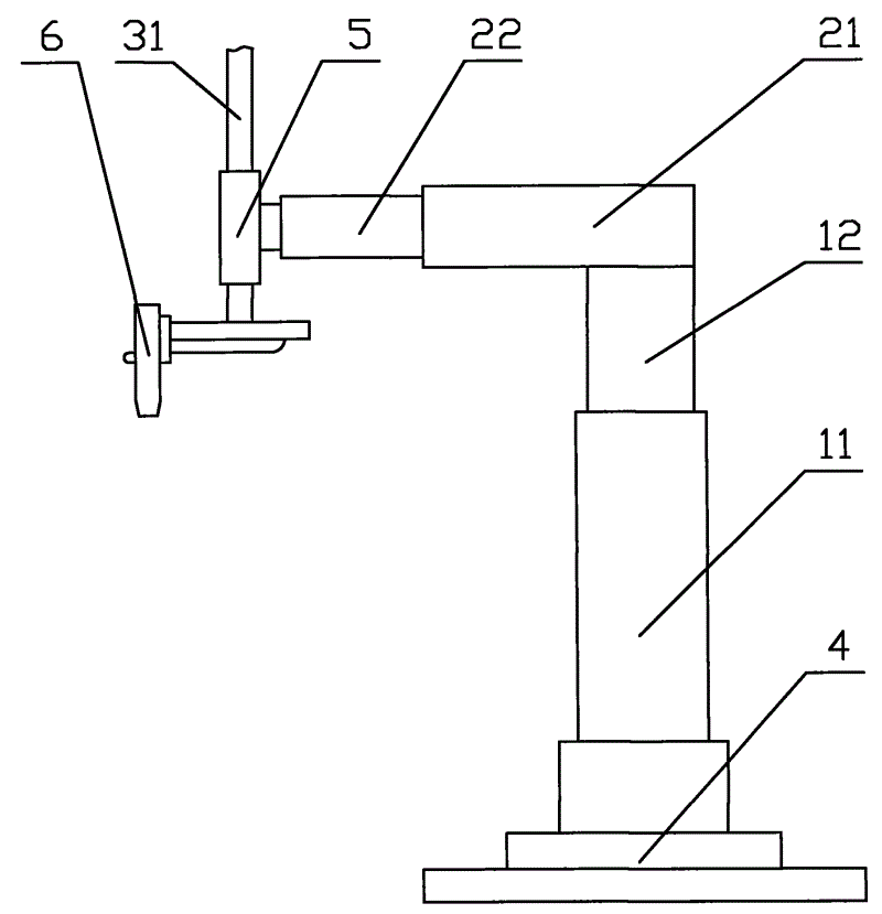
附图为本实用新型的一种实施例。Accompanying drawing is a kind of embodiment of the utility model.
附图中,11为第一气缸的缸体,12为第一气缸的活塞杆,21为第二气缸的缸体,22为第二气缸的活塞杆,31为第三气缸的活塞杆,4为支座,5为导向柱,6为加油枪。In the accompanying drawings, 11 is the cylinder body of the first cylinder, 12 is the piston rod of the first cylinder, 21 is the cylinder body of the second cylinder, 22 is the piston rod of the second cylinder, 31 is the piston rod of the third cylinder, 4 is a bearing, 5 is a guide column, and 6 is a refueling gun.
具体实施方式 Detailed ways
参照附图,带有活塞的第一气缸的缸体11固定于支座4上并与地面垂直,支座4为可作周向旋转,用于调节整个加油机构的方向。第一气缸的活塞杆作为调节加油枪6垂直方向的距离,其在垂直方向的运动行程为0~600mm。与地面平行的带有活塞的第二气缸与第一气缸活塞杆12的上端连接,该第二气缸的缸体21与第一气缸的活塞杆焊接,作为加油枪水平方向距离调节的第二气缸的活塞杆,其在水平方向的运动行程为0~400mm。带导向孔的导向柱5的圆周壁上延伸出一螺纹段,导向柱通过该螺纹段与第二气缸的活塞杆22端部连接。第三气缸的活塞杆31一端穿过导向柱孔并与导向柱滑动配合,加油枪6与第三气缸的活塞杆一端的端部连接。第三气缸缸体(图中未示出)的角度可作调节,用于微调加油枪与发动机加油孔之间的距离。当调节第三气缸的缸体角度时,加油枪的角度也随之发生改变。所述第一气缸、第二气缸以及第三气缸的活塞杆均为单杆活塞。With reference to accompanying drawing, the
本实用新型的执行机构由PLC控制其对发动机加注燃油的工作,当需要加注燃油的发动机到达定位气缸位置时,由红外线传感机构检测后发出信号给PLC,PLC控制定位气缸将发动机夹紧后,控制定位气缸上升到设定加油枪高度位置。PLC控制第二气缸的活塞杆伸出,当第二气缸活塞伸出加油枪对准发动机油孔位置时,第二气缸的活塞杆伸出到位,PLC控制燃油加注电磁阀打开,对发动机进行燃油加注。当检测燃油的流量计检测加注到设定的量后,流量计发出信号,由PLC控制关闭燃油加注电磁阀,燃油加注完成;PLC延时后控制第二气缸的活塞杆复位,当第二气缸的活塞杆到位后发出放行指令,定位气缸复位并将夹持的发动机松驰,放行加注燃油完毕的发动机。PLC复位,放行下一台发动机作加注燃油工作。如此循环,逐台将生产线上的发动机加注燃油。The executive mechanism of the utility model is controlled by the PLC to fill the engine with fuel. When the engine that needs to be filled with fuel reaches the position of the positioning cylinder, it will send a signal to the PLC after being detected by the infrared sensor, and the PLC will control the positioning cylinder to clamp the engine. After that, control the positioning cylinder to rise to the height position of the set fuel gun. The PLC controls the extension of the piston rod of the second cylinder. When the piston of the second cylinder stretches out the refueling gun and aligns with the position of the engine oil hole, the piston rod of the second cylinder extends to the right position. The PLC controls the solenoid valve for fuel filling to open, and the engine Fuel up. When the flow meter for detecting fuel detects that the fuel filling reaches the set amount, the flow meter sends out a signal, and the PLC controls to close the fuel filling solenoid valve, and the fuel filling is completed; after a delay, the PLC controls the piston rod of the second cylinder to reset, when After the piston rod of the second cylinder is in place, a release command is issued, the positioning cylinder is reset and the clamped engine is relaxed, and the engine that has been filled with fuel is released. The PLC is reset, and the next engine is released for fuel filling. In such a cycle, the engines on the production line are filled with fuel one by one.
经过测验,上述执行机构结合PLC使用,燃油加注量可以10ml为步进单位进行调整,加油节拍≤10秒/每升(不包括辅助时间);并且,燃油加注精度为±1%(加注量200ml以上)。因此,上述执行机构通过与PLC结合,加注燃油的工作效率得到提高。After testing, the above-mentioned actuators are used in combination with PLC, the fuel filling volume can be adjusted in 10ml step units, and the fueling cycle is ≤10 seconds/liter (excluding auxiliary time); and the fuel filling accuracy is ±1% (plus The injection volume is more than 200ml). Therefore, the above-mentioned actuator is combined with the PLC to improve the work efficiency of fuel filling.
Claims (4)
Priority Applications (1)
| Application Number | Priority Date | Filing Date | Title |
|---|---|---|---|
| CNU2008200974827U CN201151663Y (en) | 2008-01-15 | 2008-01-15 | Actuating mechanism of automatic oil dispenser |
Applications Claiming Priority (1)
| Application Number | Priority Date | Filing Date | Title |
|---|---|---|---|
| CNU2008200974827U CN201151663Y (en) | 2008-01-15 | 2008-01-15 | Actuating mechanism of automatic oil dispenser |
Publications (1)
| Publication Number | Publication Date |
|---|---|
| CN201151663Y true CN201151663Y (en) | 2008-11-19 |
Family
ID=40127341
Family Applications (1)
| Application Number | Title | Priority Date | Filing Date |
|---|---|---|---|
| CNU2008200974827U Expired - Fee Related CN201151663Y (en) | 2008-01-15 | 2008-01-15 | Actuating mechanism of automatic oil dispenser |
Country Status (1)
| Country | Link |
|---|---|
| CN (1) | CN201151663Y (en) |
Cited By (5)
| Publication number | Priority date | Publication date | Assignee | Title |
|---|---|---|---|---|
| CN104445033A (en) * | 2014-11-10 | 2015-03-25 | 苏州环球集团链传动有限公司 | In-sleeve automatic oiling machine |
| CN105384133A (en) * | 2015-11-25 | 2016-03-09 | 浙江吉利汽车研究院有限公司 | Intelligent autonomous oil filling device and control method |
| CN107628586A (en) * | 2017-10-18 | 2018-01-26 | 重庆博昂科技有限公司 | A kind of automatic refuelling machine for engine line |
| CN107806356A (en) * | 2017-10-18 | 2018-03-16 | 重庆博昂科技有限公司 | Dip angle regulating device |
| CN112777553A (en) * | 2019-11-07 | 2021-05-11 | 中国石油化工股份有限公司 | Automatic oiling robot |
-
2008
- 2008-01-15 CN CNU2008200974827U patent/CN201151663Y/en not_active Expired - Fee Related
Cited By (6)
| Publication number | Priority date | Publication date | Assignee | Title |
|---|---|---|---|---|
| CN104445033A (en) * | 2014-11-10 | 2015-03-25 | 苏州环球集团链传动有限公司 | In-sleeve automatic oiling machine |
| CN105384133A (en) * | 2015-11-25 | 2016-03-09 | 浙江吉利汽车研究院有限公司 | Intelligent autonomous oil filling device and control method |
| CN105384133B (en) * | 2015-11-25 | 2018-08-21 | 浙江吉利汽车研究院有限公司 | A kind of intelligent independent refueling device and control method |
| CN107628586A (en) * | 2017-10-18 | 2018-01-26 | 重庆博昂科技有限公司 | A kind of automatic refuelling machine for engine line |
| CN107806356A (en) * | 2017-10-18 | 2018-03-16 | 重庆博昂科技有限公司 | Dip angle regulating device |
| CN112777553A (en) * | 2019-11-07 | 2021-05-11 | 中国石油化工股份有限公司 | Automatic oiling robot |
Similar Documents
| Publication | Publication Date | Title |
|---|---|---|
| CN201151663Y (en) | Actuating mechanism of automatic oil dispenser | |
| CN107677461B (en) | Test module and system and test method for the experiment of oil-pressure damper orifice valve | |
| CN104089769B (en) | Reciprocating type liquid shock absorber simulation test device | |
| CN105904210A (en) | Assembly test line for gear-shifting assistance air cylinders and assembly test method | |
| CN202166597U (en) | Rapid testing device for permeability of rock | |
| JP6154487B2 (en) | Method and apparatus for determining fuel quality | |
| CN205798913U (en) | Power assisted gearshift cylinder assembling p-wire | |
| CN101201287A (en) | Device for testing product air leakage | |
| CN204984684U (en) | Gasoline engine directly spouts formula sprayer performance detecting system | |
| CN201158583Y (en) | Pneumatic constant volume rotary liquid filling machine | |
| CN101949754A (en) | Pressurizing test bed for leak hunt of butterfly valve | |
| CN206725424U (en) | Transformer oil spectrum monitoring equipment calibration oil storage tank | |
| CN202305220U (en) | Distribution unevenness measuring device of fuel nozzle | |
| CN201770463U (en) | Servo drive pump cylinder type liquid filling mechanism | |
| CN102996312B (en) | Automatic clamping device of common rail oil atomizer detection device | |
| CN203022945U (en) | Automatic clamping device of common rail fuel injector detection equipment | |
| CN203486159U (en) | Intelligent weighing filling machine | |
| CN107014595B (en) | Pilot handle valve performance test frock based on double stepper motors | |
| CN102861790A (en) | Automobile depression flattening device controlled by hydraulic servo system | |
| CN102530811A (en) | Visible-liquid-level dual-stage buffer filling valve | |
| CN105319032B (en) | A kind of oil trap test equipment | |
| CN219038937U (en) | Full-automatic quantitative sample feeding device for oil chromatographic analysis | |
| CN203486883U (en) | Filling amount adjusting device of filling machine | |
| CN207147745U (en) | Jolt the device wriggled and tested for automotive seat | |
| CN203330960U (en) | System special for dismounting and mounting common rail oil sprayer |
Legal Events
| Date | Code | Title | Description |
|---|---|---|---|
| C14 | Grant of patent or utility model | ||
| GR01 | Patent grant | ||
| ASS | Succession or assignment of patent right |
Owner name: CHONGQING ZONGSHEN GENERAL POWER MACHINE CO., LTD. Free format text: FORMER OWNER: CHONGQING ZONGSHEN TECHNOLOGY DEVELOPMENT + RESEARCH CO. LTD. Effective date: 20101115 |
|
| C41 | Transfer of patent application or patent right or utility model | ||
| COR | Change of bibliographic data |
Free format text: CORRECT: ADDRESS; FROM: 400039 NO.25, ERLANG ROAD, SHIQIAOPU, HIGH-TECH. ZONE, CHONGQING CITY TO: 400054 CHAOYOUCHANG, BA NAN DISTRICT, CHONGQING CITY |
|
| TR01 | Transfer of patent right |
Effective date of registration: 20101115 Address after: 400054 Banan District, Chongqing fried oil field Patentee after: Chongqing Zongshen General Power Machine Co., Ltd. Address before: 400039, No. 25 Erlang Road, Chongqing hi tech Development Zone, Shiqiaopu Patentee before: Chongqing Zongshen Technology Development & Research Co., Ltd. |
|
| C17 | Cessation of patent right | ||
| CF01 | Termination of patent right due to non-payment of annual fee |
Granted publication date: 20081119 Termination date: 20110115 |