CN201166370Y - Continuous casting torch - Google Patents
Continuous casting torch Download PDFInfo
- Publication number
- CN201166370Y CN201166370Y CNU2008201015343U CN200820101534U CN201166370Y CN 201166370 Y CN201166370 Y CN 201166370Y CN U2008201015343 U CNU2008201015343 U CN U2008201015343U CN 200820101534 U CN200820101534 U CN 200820101534U CN 201166370 Y CN201166370 Y CN 201166370Y
- Authority
- CN
- China
- Prior art keywords
- cutting
- hole
- cutting nozzle
- oxygen
- torch
- Prior art date
- Legal status (The legal status is an assumption and is not a legal conclusion. Google has not performed a legal analysis and makes no representation as to the accuracy of the status listed.)
- Expired - Fee Related
Links
Images


Landscapes
- Gas Burners (AREA)
Abstract
一种连铸割枪,包括枪帽头、割嘴座及枪身,割嘴座的一端插入在枪身中与枪身固接,割嘴座的中部为轴向中空的割嘴腔,割嘴座上方开有燃气孔、切割氧孔、预热氧孔、进水孔及回水孔,切割氧孔与中空的割嘴腔同轴相通,燃气孔、预热氧孔分别通过燃气道、预热氧通道与割嘴腔相通,枪帽头通过螺纹与割嘴座上的割嘴腔下部连接,割嘴座中部的外径小于两端的外径,割嘴座中部与枪身形成环形腔,该环形腔与割嘴座上方的进水孔、回水孔相通。本实用新型的连铸割枪,使用时,连铸割嘴插入割嘴座上的割嘴腔中,通过枪帽头,即可将连铸割嘴固定在割嘴座上。它与现有的连铸割枪相比,具有结构简单、使用方便的特点,同时,还可达到节约燃气、氧气的节能效果。
A continuous casting cutting torch, comprising a cap head, a cutting nozzle seat and a torch body, one end of the cutting nozzle seat is inserted into the torch body and fixedly connected with the torch body, the middle part of the cutting nozzle seat is an axially hollow cutting nozzle cavity, the cutting There are gas holes, cutting oxygen holes, preheating oxygen holes, water inlet holes and return water holes on the top of the nozzle seat. The cutting oxygen holes communicate with the hollow cutting nozzle cavity coaxially. The preheating oxygen channel communicates with the cutting nozzle cavity, and the torch cap head is connected with the lower part of the cutting nozzle cavity on the cutting nozzle seat through threads. , the annular cavity communicates with the water inlet hole and the water return hole above the cutting nozzle seat. When the continuous casting cutting torch of the utility model is in use, the continuous casting cutting nozzle is inserted into the cutting nozzle cavity on the cutting nozzle seat, and the continuous casting cutting nozzle can be fixed on the cutting nozzle seat through the gun cap head. Compared with the existing continuous casting torch, it has the characteristics of simple structure and convenient use, and at the same time, it can also achieve the energy-saving effect of saving gas and oxygen.
Description
技术领域 technical field
本实用新型涉及一种用于炼钢连铸坯火焰切割的连铸割枪。The utility model relates to a continuous casting torch used for flame cutting of steelmaking continuous casting slabs.
背景技术 Background technique
连铸割枪是炼钢工业中,连铸坯火焰切割时与割嘴配套使用的专用工具,它是将燃气、氧气及冷却水与割嘴相连的中间体。现有的连铸割枪结构复杂,使用不太方便。The continuous casting torch is a special tool used in conjunction with the cutting nozzle when the continuous casting slab is flame-cut in the steelmaking industry. It is an intermediate that connects gas, oxygen and cooling water to the cutting nozzle. The existing continuous casting torch has a complex structure and is not very convenient to use.
发明内容 Contents of the invention
本实用新型的目的就是提供一种结构简单、使用方便的连铸割枪。The purpose of the utility model is to provide a continuous casting torch with simple structure and convenient use.
本实用新型的连铸割枪,包括枪帽头、割嘴座及枪身,割嘴座的一端插入在枪身中与枪身固接,割嘴座的中部为轴向中空的割嘴腔,割嘴腔中开有两道环形凹槽,割嘴座上方开有燃气孔、切割氧孔、预热氧孔、进水孔及回水孔,切割氧孔与中空的割嘴腔同轴相通,燃气孔、预热氧孔分别通过燃气道、预热氧通道、环形凹槽与割嘴腔相通,割嘴腔下部开有内螺纹,枪帽头通过螺纹与割嘴座上的割嘴腔下部连接,割嘴座中部的外径小于两端的外径,割嘴座中部与枪身形成环形腔,该环形腔与割嘴座上方的进水孔、回水孔相通。燃气管、切割氧管、预热氧管、进水管、出水管分别与燃气孔、切割氧孔、预热氧孔、进水孔、回水孔相接。The continuous casting cutting torch of the present utility model includes a cap head, a cutting nozzle seat and a torch body, one end of the cutting nozzle seat is inserted into the torch body and fixedly connected with the torch body, and the middle part of the cutting nozzle seat is an axially hollow cutting nozzle cavity , there are two annular grooves in the cutting nozzle cavity, and there are gas holes, cutting oxygen holes, preheating oxygen holes, water inlet holes and return water holes above the cutting nozzle seat, and the cutting oxygen holes are coaxial with the hollow cutting nozzle cavity The gas hole and the preheating oxygen hole communicate with the cutting nozzle cavity through the gas channel, the preheating oxygen channel and the annular groove respectively. The lower part of the cavity is connected, the outer diameter of the middle part of the cutting nozzle seat is smaller than the outer diameter of both ends, the middle part of the cutting nozzle seat and the gun body form an annular cavity, and the annular cavity communicates with the water inlet hole and the water return hole above the cutting nozzle seat. The gas pipe, the cutting oxygen pipe, the preheating oxygen pipe, the water inlet pipe and the water outlet pipe are respectively connected with the gas hole, the cutting oxygen hole, the preheating oxygen hole, the water inlet hole and the water return hole.
本实用新型的连铸割枪,使用时,连铸割嘴插入割嘴座上的割嘴腔中,通过枪帽头,即可将连铸割嘴固定在割嘴座上。它与现有的连铸割枪相比,具有结构简单、使用方便的特点,同时,还可达到节约燃气、氧气的节能效果。When the continuous casting cutting torch of the utility model is in use, the continuous casting cutting nozzle is inserted into the cutting nozzle cavity on the cutting nozzle seat, and the continuous casting cutting nozzle can be fixed on the cutting nozzle seat through the cap head. Compared with the existing continuous casting torch, it has the characteristics of simple structure and convenient use, and at the same time, it can also achieve the energy-saving effect of saving gas and oxygen.
附图说明 Description of drawings
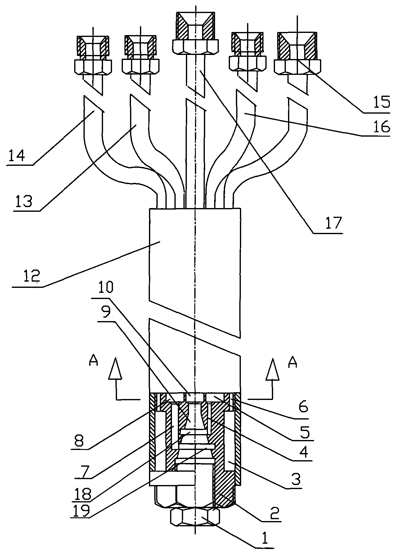
图1为本实用新型结构示意图;Fig. 1 is a structural representation of the utility model;
图2为图1中A-A面剖示图。Fig. 2 is a sectional view of plane A-A in Fig. 1 .
具体实施方式Detailed ways
一种连铸割枪,包括枪帽头1、割嘴座2及枪身12,割嘴座2的一端插入在枪身12中与枪身12固接,割嘴座2的中部为轴向中空的割嘴腔9,割嘴腔9中开有两道环形凹槽18、19,割嘴座2上方开有燃气孔8、切割氧孔10、预热氧孔5、进水孔11及回水孔6,切割氧孔10与中空的割嘴腔9同轴相通,燃气孔8通过燃气道7、环形凹槽19与割嘴腔9相通,预热氧孔5通过预热氧通道4、环形凹槽18与割嘴腔9相通,割嘴腔9下部开有内螺纹,枪帽头1通过螺纹与割嘴座2上的割嘴腔9下部连接,割嘴座2中部的外径小于两端的外径,割嘴座2中部与枪身12形成环形腔3,该环形腔3与割嘴座2上方的进水孔11、回水孔6相通,通过循环水可对整个割枪、割嘴进行冷却。燃气管15、切割氧管17、预热氧管13、进水管16、出水管14分别与燃气孔8、切割氧孔10、预热氧孔5、进水孔11、回水孔6相接。所述的进水孔11直径为4-7mm,燃气孔8直径为2-4mm,切割氧孔10直径为3-7mm,预热氧孔5直径为2-5mm,回水孔6直径为1-3mm。A continuous casting cutting torch, comprising a
Claims (2)
Priority Applications (1)
| Application Number | Priority Date | Filing Date | Title |
|---|---|---|---|
| CNU2008201015343U CN201166370Y (en) | 2008-02-29 | 2008-02-29 | Continuous casting torch |
Applications Claiming Priority (1)
| Application Number | Priority Date | Filing Date | Title |
|---|---|---|---|
| CNU2008201015343U CN201166370Y (en) | 2008-02-29 | 2008-02-29 | Continuous casting torch |
Publications (1)
| Publication Number | Publication Date |
|---|---|
| CN201166370Y true CN201166370Y (en) | 2008-12-17 |
Family
ID=40191760
Family Applications (1)
| Application Number | Title | Priority Date | Filing Date |
|---|---|---|---|
| CNU2008201015343U Expired - Fee Related CN201166370Y (en) | 2008-02-29 | 2008-02-29 | Continuous casting torch |
Country Status (1)
| Country | Link |
|---|---|
| CN (1) | CN201166370Y (en) |
Cited By (3)
| Publication number | Priority date | Publication date | Assignee | Title |
|---|---|---|---|---|
| CN101839485A (en) * | 2010-06-18 | 2010-09-22 | 青岛上联机械设备有限公司 | Autoignition dual ring fast cutting torch |
| CN102330983A (en) * | 2011-07-12 | 2012-01-25 | 陈寅明 | Continuous casting cutting gun |
| CN109226708A (en) * | 2018-11-21 | 2019-01-18 | 西峡龙成特种材料有限公司 | Online facing attachment and conticaster |
-
2008
- 2008-02-29 CN CNU2008201015343U patent/CN201166370Y/en not_active Expired - Fee Related
Cited By (4)
| Publication number | Priority date | Publication date | Assignee | Title |
|---|---|---|---|---|
| CN101839485A (en) * | 2010-06-18 | 2010-09-22 | 青岛上联机械设备有限公司 | Autoignition dual ring fast cutting torch |
| CN101839485B (en) * | 2010-06-18 | 2012-05-09 | 青岛上联机械设备有限公司 | Autoignition dual ring fast cutting torch |
| CN102330983A (en) * | 2011-07-12 | 2012-01-25 | 陈寅明 | Continuous casting cutting gun |
| CN109226708A (en) * | 2018-11-21 | 2019-01-18 | 西峡龙成特种材料有限公司 | Online facing attachment and conticaster |
Similar Documents
| Publication | Publication Date | Title |
|---|---|---|
| CN103658483B (en) | Cup and rod integrated part type forge piece heat extruding die | |
| CN205245173U (en) | Top air intake burner | |
| US20100193608A1 (en) | Nozzle of a gas burner | |
| CN205664377U (en) | Burner | |
| CN201639849U (en) | Directly adjusted plasma heating gun | |
| CN201866769U (en) | Anti-backfire gas burner | |
| JP4863693B2 (en) | Two-fluid injection nozzle and oil burner | |
| CN201487958U (en) | Built-in high-efficiency burner | |
| CN202598522U (en) | Combustor for gas stove | |
| CN201285047Y (en) | Energy-saving natural gas cutting nozzle | |
| CN202910435U (en) | Quick-change continuous casting billet cutting nozzle | |
| CN209068508U (en) | Natural gas conticaster cutting nozzle | |
| CN202253651U (en) | Industrial gas quick cutting nozzle | |
| CN201246749Y (en) | Injection type continuous casting cutting nozzle | |
| CN201779664U (en) | Quick cutting torch of propane | |
| CN208058835U (en) | Multi-layered fluid energy-saving combustion apparatus | |
| CN102003704B (en) | Swirl air inflow type evaporative burner with changeable oil absorption lining | |
| ATE472930T1 (en) | PLASMA BURNER | |
| CN201306714Y (en) | Backblowing type external premixing high-speed current equalizing burner for industrial furnace | |
| CN201259223Y (en) | High-efficiency thermal gas burner | |
| CN109611845B (en) | Manufacturing method of burner | |
| CN202943227U (en) | Cutting torch of continuous casting machine | |
| CN102393016B (en) | Evaporation-type combustor with easily replaced oil absorption lining | |
| CN207839207U (en) | A kind of cavitation chamber has the high pressure cavitation jet combination nozzle of roughness | |
| CN202062144U (en) | Multi-purpose coal gas type continuous-casting cutting gun |
Legal Events
| Date | Code | Title | Description |
|---|---|---|---|
| C14 | Grant of patent or utility model | ||
| GR01 | Patent grant | ||
| C17 | Cessation of patent right | ||
| CF01 | Termination of patent right due to non-payment of annual fee |
Granted publication date: 20081217 Termination date: 20130229 |
|
| CF01 | Termination of patent right due to non-payment of annual fee |