CN201230200Y - Protective circuit for limiting the operating power of an electrical device - Google Patents
Protective circuit for limiting the operating power of an electrical device Download PDFInfo
- Publication number
- CN201230200Y CN201230200Y CNU2008201255489U CN200820125548U CN201230200Y CN 201230200 Y CN201230200 Y CN 201230200Y CN U2008201255489 U CNU2008201255489 U CN U2008201255489U CN 200820125548 U CN200820125548 U CN 200820125548U CN 201230200 Y CN201230200 Y CN 201230200Y
- Authority
- CN
- China
- Prior art keywords
- power
- protective circuit
- electric equipment
- resistor
- described electric
- Prior art date
- Legal status (The legal status is an assumption and is not a legal conclusion. Google has not performed a legal analysis and makes no representation as to the accuracy of the status listed.)
- Expired - Lifetime
Links
- 230000001681 protective effect Effects 0.000 title claims description 27
- 230000004044 response Effects 0.000 claims abstract description 10
- 239000003990 capacitor Substances 0.000 claims description 32
- 230000003247 decreasing effect Effects 0.000 claims description 5
- 230000004913 activation Effects 0.000 claims description 4
- 230000003213 activating effect Effects 0.000 claims description 2
- 230000006698 induction Effects 0.000 claims 4
- 230000008676 import Effects 0.000 claims 1
- 230000000750 progressive effect Effects 0.000 claims 1
- 238000000034 method Methods 0.000 description 14
- 238000010304 firing Methods 0.000 description 13
- 230000008569 process Effects 0.000 description 13
- 239000007787 solid Substances 0.000 description 12
- 238000010586 diagram Methods 0.000 description 8
- 238000005070 sampling Methods 0.000 description 8
- 230000015556 catabolic process Effects 0.000 description 7
- 238000005286 illumination Methods 0.000 description 6
- 230000000630 rising effect Effects 0.000 description 5
- 230000033228 biological regulation Effects 0.000 description 4
- 230000001960 triggered effect Effects 0.000 description 4
- XUIMIQQOPSSXEZ-UHFFFAOYSA-N Silicon Chemical compound [Si] XUIMIQQOPSSXEZ-UHFFFAOYSA-N 0.000 description 3
- 230000009467 reduction Effects 0.000 description 3
- 229910052710 silicon Inorganic materials 0.000 description 3
- 239000010703 silicon Substances 0.000 description 3
- 230000009471 action Effects 0.000 description 2
- 230000008859 change Effects 0.000 description 2
- 230000007423 decrease Effects 0.000 description 2
- 230000007935 neutral effect Effects 0.000 description 2
- 238000004904 shortening Methods 0.000 description 2
- 230000000295 complement effect Effects 0.000 description 1
- 238000001514 detection method Methods 0.000 description 1
- 238000007599 discharging Methods 0.000 description 1
- 230000005611 electricity Effects 0.000 description 1
- 230000007613 environmental effect Effects 0.000 description 1
- 239000002803 fossil fuel Substances 0.000 description 1
- 230000004048 modification Effects 0.000 description 1
- 238000012986 modification Methods 0.000 description 1
- 238000006467 substitution reaction Methods 0.000 description 1
- 230000001360 synchronised effect Effects 0.000 description 1
- 239000002699 waste material Substances 0.000 description 1
Images


Classifications
-
- H—ELECTRICITY
- H02—GENERATION; CONVERSION OR DISTRIBUTION OF ELECTRIC POWER
- H02H—EMERGENCY PROTECTIVE CIRCUIT ARRANGEMENTS
- H02H9/00—Emergency protective circuit arrangements for limiting excess current or voltage without disconnection
- H02H9/02—Emergency protective circuit arrangements for limiting excess current or voltage without disconnection responsive to excess current
Landscapes
- Engineering & Computer Science (AREA)
- Power Engineering (AREA)
- Circuit Arrangement For Electric Light Sources In General (AREA)
Abstract
Description
技术领域 technical field
本实用新型涉及限制电气设备的工作功率的保护电路,具体地而非唯一地涉及照明设备。The utility model relates to a protection circuit for limiting the working power of electrical equipment, in particular but not exclusively to lighting equipment.
背景技术 Background technique
为了保护环境,在世界范围内,人们变得越来越谨慎并且大体上承认了应该最小化对矿物燃料的使用,具体地,对来自主干/家用电源的电力的使用。Worldwide, in order to protect the environment, people are becoming more cautious and generally acknowledging that the use of fossil fuels, in particular electricity from mains/domestic power supplies, should be minimized.
照明是能够由普通公众容易实现能量节约的领域。例如,对于通常不苛求照明强度的普通照明用途,推荐相对低额定功率的电灯泡。在某些司法管辖领域(jurisdiction)中,已经制定了将照明设备等的工作约束在特定的额定瓦数以下的规定,例如对于吊扇上的照明部件(light kit)约束在109W以下。Lighting is an area where energy savings can be readily achieved by the general public. For example, relatively low wattage rated light bulbs are recommended for general lighting purposes where light intensity is generally not critical. In some jurisdictions there have been regulations restricting the operation of lighting equipment etc. below a certain rated wattage, for example 109W for a light kit on a ceiling fan.
然而,由于疏忽或无忧无虑(lightheartedness),一些人为了更明亮的照明可能仍然使用过功率的电灯泡,这将引起对能量不必要的浪费并且可能是危险的。However, due to negligence or lightheartedness, some people may still use overpowered light bulbs for brighter lighting, which causes unnecessary waste of energy and can be dangerous.
本实用新型要通过提供一种限制电气设备的工作功率的新的或改进的保护电路,来消除或至少减轻这样的问题或缺点。The present invention seeks to eliminate or at least alleviate such problems or disadvantages by providing a new or improved protection circuit which limits the operating power of electrical equipment.
发明内容 Contents of the invention
根据本实用新型,提供了一种将与电源连接的电气设备的工作功率限制在预定的额定功率以下的保护电路,该保护电路包括:According to the utility model, there is provided a protection circuit that limits the working power of the electrical equipment connected to the power supply below the predetermined rated power, the protection circuit includes:
与电气设备连接的开关设备,调整从电源供应至电气设备的电功率;Switchgear connected to electrical equipment to regulate the electrical power supplied from the mains to the electrical equipment;
感应器,感应与电气设备的工作功率相关的参数;以及sensors for sensing parameters related to the operating power of electrical equipment; and
比较器,比较感应器感应的参数以确定不期望的工作状况,在所述工作状况下电气设备以超过预定的额定功率的功率进行工作;以及响应于确定这样的不期望的工作状况,提供输出信号以控制开关设备将供应电气设备的电功率调整到预定的额定功率以下,同时保持电流流经电气设备。a comparator for comparing a parameter sensed by the sensor to determine an undesired operating condition in which the electrical device is operating at a power in excess of a predetermined power rating; and providing an output in response to determining such an undesired operating condition Signal to control the switching device to adjust the electrical power supplied to the electrical equipment below the predetermined rated power, while maintaining the current flow through the electrical equipment.
优选地,感应器包括:电压感应设备,感应所述电气设备的工作电压,该工作电压是所述参数。Preferably, the sensor includes: a voltage sensing device for sensing the operating voltage of the electrical device, and the operating voltage is the parameter.
更优选地,电压感应设备包括:串联连接在所述电气设备和所述电源之间的第一电阻器,该第一电阻器在电气设备侧具有一个感应所述电气设备的工作电压的端子。More preferably, the voltage sensing device includes: a first resistor connected in series between the electric device and the power supply, the first resistor having a terminal on the electric device side for sensing the operating voltage of the electric device.
进一步更优选地,比较器包括电压比较器,该电压比较器具有:第一输入端,通过第二电阻器连接到第一电阻器的端子以输入所述电气设备的工作电压;以及第二输入端,与在电源侧的第一电阻器的另一端子连接以输入作为比较的参考而出现在第一电阻器的另一端子的电压。Still more preferably, the comparator includes a voltage comparator having: a first input terminal connected to a terminal of the first resistor through a second resistor to input the operating voltage of the electrical device; and a second input terminal connected to the other terminal of the first resistor on the power supply side to input the voltage appearing at the other terminal of the first resistor as a reference for comparison.
进一步更优选地,第一电阻器的另一端子与所述电源直接连接,使得将所述电源的电压作为参考。Still more preferably, the other terminal of the first resistor is directly connected to the power supply so that the voltage of the power supply is used as a reference.
优选地,感应器包括电流感应设备,电流感应设备具有串联连接在所述电气设备与所述电源之间的电阻器以感应所述电气设备的工作电流,该工作电流是所述参数。Preferably, the inductor comprises a current sensing device having a resistor connected in series between said electrical device and said power supply to sense an operating current of said electrical device, which is said parameter.
进一步优选地,比较器包括电压比较器,电压比较器具有分别与电阻器的相对的端子连接的两个输入端,通过比较由所述工作电流在电阻器上产生的电势差,来确定所述不期望的工作状况。Further preferably, the comparator includes a voltage comparator having two input terminals respectively connected to opposite terminals of the resistor, and determining the difference by comparing the potential difference generated on the resistor by the operating current. desired working conditions.
在优选实施例中,开关设备包括继电器,将继电器布置为在至少两个第一和第二电路之间的进行切换,第一电路将所述电气设备正常连接至所述电源,第二电路在确定所述不期望的状况之后将所述电气设备连接至所述电源。In a preferred embodiment, the switching device comprises a relay arranged to switch between at least two first and second circuits, the first circuit normally connecting said electrical device to said power supply, and the second circuit in Connecting the electrical device to the power source after determining the undesirable condition.
更优选地,第一电路具有相对低的电阻,以将所述电气设备正常连接至所述电源,第二电路具有相对高的电阻,以在确定所述不期望的状况之后将所述电气设备连接至所述电源,从而将供应给所述电气设备的电功率减小至预定的额定功率以下。More preferably, the first circuit has a relatively low resistance to normally connect the electrical device to the power source and the second circuit has a relatively high resistance to connect the electrical device to connected to the power source, thereby reducing the electrical power supplied to the electrical device below a predetermined power rating.
更优选地,开关设备包括将所述电气设备连接至所述电源的固态开关,该固态开关具有控制端子,该控制端子可由在不同电阻的第一和第二电路之间的继电器切换,以控制固态开关的导通的占空比。More preferably, the switching device comprises a solid state switch connecting said electrical device to said power supply, the solid state switch having control terminals switchable by a relay between first and second circuits of different resistance to control The duty cycle of the solid-state switch's conduction.
进一步更优选地,固态开关包括三端可控硅器件,通过由继电器所切换到的第一和第二电路之一进行充电的电容器对三端可控硅器件的控制端子进行控制。Still more preferably, the solid state switch comprises a triac, the control terminal of which is controlled by a capacitor charged by one of the first and second circuits to which the relay is switched.
更优选地,保护电路包括连接在比较器和继电器之间的锁存单元,将所述比较器的输出信号锁存至继电器使得继电器将保持激活。More preferably, the protection circuit includes a latch unit connected between the comparator and the relay, latching the output signal of the comparator to the relay so that the relay will remain active.
更优选地,继电器包括电磁继电器,所述电磁继电器具有开关和操作开关的电磁体。More preferably, the relay comprises an electromagnetic relay having a switch and an electromagnet operating the switch.
在优选实施例中,开关设备包括:将所述电气设备连接至所述电源的固态开关,该固态开关具有控制端子;以及与控制端子连接的触发单元,响应于比较器的所述输出信号提供一系列时控触发信号以在渐进的不同起动角度处使固态开关导通,从而控制固态开关的导通的占空比,其中每个起动角度在预定的时间周期上。In a preferred embodiment, the switching device comprises: a solid-state switch connecting said electrical device to said power supply, the solid-state switch having a control terminal; and a trigger unit connected to the control terminal, responsive to said output signal of the comparator providing A series of timed trigger signals to turn on the solid state switch at progressively different firing angles, each firing angle over a predetermined period of time, thereby controlling the duty cycle of the solid state switch's conduction.
更优选地,保护电路包括连接在比较器和触发单元之间的控制器,对触发单元的触发信号的定时和起动角度进行控制。More preferably, the protection circuit includes a controller connected between the comparator and the trigger unit to control the timing and starting angle of the trigger signal of the trigger unit.
进一步更优选地,控制器包括:计数器,以所述预定的时间间隔提供一系列控制信号,以对触发单元提供的触发信号的定时进行控制。Still more preferably, the controller includes: a counter, which provides a series of control signals at the predetermined time interval, so as to control the timing of the trigger signal provided by the trigger unit.
进一步更优选地,触发单元包括:电容器以及与固态开关的控制端子连接的多个电阻通路,每个电阻通路具有不同的电阻以渐进地调整电容器的充电时间以及依次地由触发单元提供的触发信号的起动角度,由计数器的各个控制信号交替地激活电阻通路。Still more preferably, the triggering unit comprises: a capacitor and a plurality of resistive paths connected to the control terminals of the solid-state switch, each resistive path having a different resistance to gradually adjust the charging time of the capacitor and the triggering signal sequentially provided by the triggering unit The starting angle of the counter is activated alternately by the respective control signals of the counter.
进一步更优选地,计数器具有输出各个控制信号的多个输出端,每个电阻通路包括电阻器以及固态开关,以及该固态开关具有与计数器的各个输出端连接的激活用控制端子。Still more preferably, the counter has a plurality of outputs outputting respective control signals, each resistive path comprises a resistor and a solid state switch, and the solid state switch has an activation control terminal connected to the respective output of the counter.
进一步更优选地,控制器包括与触发单元连接的计时器,响应于由计数器提供的每个控制信号对触发单元的触发信号的起动角度进行渐进地调整。Still more preferably, the controller includes a timer connected to the trigger unit, and progressively adjusts the firing angle of the trigger signal of the trigger unit in response to each control signal provided by the counter.
进一步更优选地,计数器具有将一系列控制信号输出至计时器的与计时器连接的至少一个输出端,控制信号是二进制信号。Still more preferably, the counter has at least one output connected to the timer that outputs a series of control signals to the timer, the control signals being binary signals.
优选地,开关设备最初以最大功率将电功率从所述电源发送至所述电气设备,随后将所述电功率减小至预定的额定功率以下。Preferably, the switching device initially sends electrical power from said power source to said electrical device at maximum power and subsequently reduces said electrical power below a predetermined rated power.
优选地,控制器可操作地增大触发单元的触发信号的起动角度,以减小固态开关的导通的占空比,使得将所述电功率减小至预定的额定功率以下。Preferably, the controller is operable to increase the firing angle of the firing signal of the firing unit to reduce the duty cycle of conduction of the solid state switch such that the electrical power is reduced below a predetermined rated power.
优选地,控制器可操作地减小触发单元的触发信号的起动角度以增大固态开关的导通的占空比,使得增大所述电功率,直到其超过预定的额定功率,随后增大触发单元的触发信号的起动角度,以减小固态开关的导通的占空比,使得将所述电功率减小至预定的额定功率以下。Preferably, the controller is operable to decrease the firing angle of the triggering signal of the triggering unit to increase the duty cycle of the conduction of the solid state switch such that the electrical power is increased until it exceeds a predetermined power rating, and then the triggering is increased. The activation angle of the trigger signal of the unit to reduce the duty cycle of the conduction of the solid state switch so as to reduce the electric power below a predetermined rated power.
优选地,预定的额定功率是190瓦特。Preferably, the predetermined power rating is 190 watts.
附图说明 Description of drawings
现在将通过参考附图仅以示例的方式更具体地描述本实用新型,在附图中:The invention will now be described more particularly, by way of example only, with reference to the accompanying drawings, in which:
图1是根据本实用新型的包括并入了保护电路的照明部件在内的电吊扇的底透视图;1 is a bottom perspective view of an electric ceiling fan including a lighting component incorporating a protective circuit according to the present invention;
图2是图1的吊扇的顶透视图,示出了容纳在位于吊扇安装轴上端的箱体中的保护电路;Fig. 2 is a top perspective view of the ceiling fan of Fig. 1, showing the protection circuit housed in the housing at the upper end of the ceiling fan's mounting shaft;
图3是图2的安装轴的上端的放大的透视图,更清楚地示出了箱体;Figure 3 is an enlarged perspective view of the upper end of the mounting shaft of Figure 2, more clearly showing the housing;
图4是图3的箱体的敞开的透视图,揭示了保护电路内部;Figure 4 is an open perspective view of the case of Figure 3, revealing the inside of the protection circuit;
图5是图4的保护电路的第一实施例的示意性电路图;5 is a schematic circuit diagram of a first embodiment of the protection circuit of FIG. 4;
图6是图4的保护电路的第二实施例的示意性电路图;6 is a schematic circuit diagram of a second embodiment of the protection circuit of FIG. 4;
图7是演示了图5和6的保护电路的工作过程的流程图;Figure 7 is a flow chart illustrating the working process of the protection circuit of Figures 5 and 6;
图8是图4的保护电路的第三实施例的示意性电路图;8 is a schematic circuit diagram of a third embodiment of the protection circuit of FIG. 4;
图9是演示了图8的保护电路的工作过程的流程图;Fig. 9 is a flow chart illustrating the working process of the protection circuit of Fig. 8;
图10是图4的保护电路的第四实施例的示意性电路图;10 is a schematic circuit diagram of a fourth embodiment of the protection circuit of FIG. 4;
图11是演示了图10的保护电路的工作过程的流程图;Fig. 11 is a flowchart illustrating the working process of the protection circuit of Fig. 10;
图12是图4的保护电路的第五实施例的示意性电路图;12 is a schematic circuit diagram of a fifth embodiment of the protection circuit of FIG. 4;
图13是演示了图12的保护电路的工作过程的流程图;Fig. 13 is a flow chart illustrating the working process of the protection circuit of Fig. 12;
图14是图4的保护电路的第六实施例的示意性电路图;14 is a schematic circuit diagram of a sixth embodiment of the protection circuit of FIG. 4;
图15是演示了图14的保护电路的工作过程的流程图;Fig. 15 is a flow chart illustrating the working process of the protection circuit of Fig. 14;
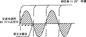
图16A到16N是,在由图4的保护电路实现的相位控制所产生的逐渐减小的占空比(duty cycle)处,照明部件的工作电压的波形图;以及16A to 16N are waveform diagrams of operating voltages of lighting components at gradually decreasing duty cycles produced by the phase control implemented by the protection circuit of FIG. 4; and
图17和18是示出了照明部件的工作电压的占空比与因此而消耗的功率之间的关系的表格。17 and 18 are tables showing the relationship between the duty cycle of the operating voltage of the lighting part and the power consumed thereby.
具体实施方式 Detailed ways
首先参考附图中的图1至图5以及图7,示出了电气设备,也就是并入了体现本实用新型的保护电路100的电吊扇10。吊扇10具有典型的结构,该典型的结构包括:利用垂直的安装轴12吊在天花板上的电动机外壳11,在外壳11中并且驱动四个或五个水平的风扇叶片15的风扇电动机13,以及安装在电动机13下面的开关杯(switch cup)14。Referring first to Figures 1 to 5 and 7 of the accompanying drawings, there is shown an electrical device, that is, an
所关注类型的吊扇10包括在其底部的向房间添加环境光(ambientlight)的照明部件L,它安装在开关杯14上。如本领域通常所知,利用固定各白炽灯泡5的(例如)四个灯座4组成照明部件L。一对电缆2通过所说的保护电路100和开关杯14上的打开/关闭照明部件L的ON/OFF开关(未示出)将灯座4连接到主干交流(AC)电源M。A
出于环境保护或安全原因或为了满足某些安全规定,对于照明部件L也就是所有电灯泡5一起,存在额定功率或工作瓦数上的限制,这是应该遵守的过载限制。例如,瓦数限制是:如有关当局设定的190W,这对于115V(110-120V)的主干电压转化为约1.65A的最大负载电流。为了满足该规定,可以将标准的40W用作电灯泡5。For environmental protection or safety reasons or to meet certain safety regulations, there is a limit on the rated power or operating wattage for the lighting part L, ie all
由于疏忽或随意的违反规定,一些人为了更明亮的照明可能使用过度的瓦数(例如,每个60W或甚至100W)的电灯泡。这不仅违反规定而且的确是危险的。保护电路100自动地将照明部件L的工作限制在前述的190W额定瓦数以下。Due to negligence or random violation of regulations, some people may use excessive wattage (eg, 60W or even 100W each) light bulbs for brighter lighting. Not only is this against the rules but it is indeed dangerous. The
在图5的电路图中,如从主干电源M到照明部件L,保护电路100包括直流(DC)电源单元110、负载电压采样单元120、电压比较器130、信号锁存单元140、以及调光器(light dimmer)150。In the circuit diagram of FIG. 5, as from the main power supply M to the lighting part L, the
将DC电源单元110连接到主干电源M的带电端(the live)和不带电端(the neutral)。如本领域通常所知,可以利用二极管电桥以及适当的滤波电容器来实现该DC电源单元110,DC电源单元110为调光器150提供24V直流电,为其它部件提供12V直流电,或适当地提供任何其它DV电压。Connect the DC
通过使用串联连接在主干电源带电端与负载(也就是照明部件L)之间的非常小的、作为电流感应设备来监控负载电流的电阻器R1(例如0.04Ω),以及提供采样负载电压的串联的电阻器R2和可变电阻器R3,负载电压采样电路120对负载电压进行采样。电阻器R1上的电势差取决于反映照明部件L的主要工作功率的负载电流。Monitor the load current by using a very small resistor R1 (eg 0.04Ω) connected in series between the mains live terminal and the load (i.e. the lighting unit L) as a current sensing device, and provide a series connection to sample the load voltage The resistor R2 and the variable resistor R3, the load
零(或接近零)负载电流处照明部件L的负载电压实际上是主干电压,因此将该主干电压用作参考电压。通过使用电压比较器130将采样的负载电压与主干电压(也就是参考电压)相比较,能够确定或监控照明部件L的负载状况(也就是工作功率)。The load voltage of the lighting component L at zero (or close to zero) load current is actually the mains voltage, so this mains voltage is used as the reference voltage. By using the
电压比较器130具有:与用于对负载电压进行采样的电阻器R2/R3连接的第一输入端,以及与得到参考主干电压的主干带电端连接的第二输入端。通过将负载电压与主干电压相比较,电压比较器130连续不断地对照明部件的工作功率进行监控。The
通过调整可变电阻器R3而对电压比较器130进行调节,使得电压比较器130将立刻在超过1.65A限制的负载电流(也就是照明部件以190W限制以上的功率进行工作)上提供高输出信号(例如从逻辑低上升至逻辑高,如脉冲信号的上升沿),只要出现这样的状况。这是不期望的状况,在该状况下电灯泡5吸收(draw)过大的负载电流(因为其过度的瓦数),从而使调光器150跳闸以减轻可能的危险。
具体考虑电流感应电阻器R1,将所述电阻器R1相对的两端分别连接到电压比较器230的两个输入端,由此比较器230利用负载电流比较电阻器R1两端的电势差,以通过参考作为所考虑的参数的电流来监控和确定不期望的过功率工作状况。Considering specifically the current sensing resistor R1, the opposite ends of said resistor R1 are respectively connected to the two input terminals of the
利用继电器151和电阻器R4实现调光器150。继电器151是电磁型的,尽管其可以是固态型的。它具有SPDT(单刀双掷)开关152,在负载电压采样单元120与照明部件L之间的带电电路中,该SPDT开关152与跨越两个电路节点N1和N2的电阻器R4串联连接。由继电器150的电磁体153操作开关152,操作开关152在正常位置将照明部件L与主干电源M之间的电路短路,在跳闸位置将电阻器R4插入所述电路中。The dimmer 150 is implemented with a
信号锁存单元140具有与电磁体153连接的输出端,该输出端传递电压比较器130的所述输出信号,以便将开关152拨动至跳闸位置。在电压比较器130检测到照明部件L以超过190W的功率等级工作之后,将几乎立即执行这样的切换动作。The
与开关152的正常状况相比,在开关152的跳闸位置,串联连接的电阻器R4极大限制了通过照明部件L的电流,因此电灯泡5仅能以190W以下极大降低的功率等级运行。In the tripped position of the
一旦出现比较器的输出信号,信号锁存单元140就锁存和保持所述输出信号,并且这保证了一旦将继电器151跳闸(即使在极大减小了负载电流之后)继电器151将保持激活,调光器150以及此后全部保护电路100将保持跳闸。The
然后应该进行用户动作,也就是利用低功率的电灯泡替换电灯泡5,然后将照明部件L重新接电,因此保护电路100将复位然后允许190W以下的照明部件L的正常工作。A user action should then be performed, ie replace the
图7的流程图概括了以上描述的工作过程。从开始(步骤101)起,在已接电之后的0.5s中(对于白炽负载突入电流(inrush current)足够长,通常在约0.3s内),电压比较器130确定电灯泡5是否正在以190W以上的功率工作(步骤102)。如果不是,则不要求也不进行对电灯泡5的控制并且电灯泡5的照明强度保持不变(步骤103)。The flowchart in Fig. 7 summarizes the working process described above. From the beginning (step 101), within 0.5s after being powered on (long enough for an incandescent load inrush current, usually within about 0.3s), the
在工作功率超过190W的情况下,信号锁存单元140保持来自电压比较器130的高输出信号“ON”(步骤104),然后调光器150突入(kickin)并且限制照明部件L的工作电压,因此降低了电灯泡5的强度(步骤105)。In the case that the operating power exceeds 190W, the
调光器150根据电阻进行操作。为了避免电阻器R4的温度的过度上升,其电阻应该足够大(例如100kΩ)以至于充分限制负载电流。在本实施例中,尤其在不是太黑暗的环境中,负载电流将减小到这样低的等级以至于电灯泡5即使仍然在运行却将发射仅仅可注意的光。The dimmer 150 operates based on resistance. In order to avoid an excessive rise in the temperature of resistor R4, its resistance should be large enough (eg 100 kΩ) to sufficiently limit the load current. In this embodiment, especially in environments that are not too dark, the load current will be reduced to such a low level that the
值得注意的是,在保护电路100的工作过程的末端,将不关闭或断开电灯泡5并且也不打算将其关闭或断开。例如,为了提供保护电路100已经跳闸或者灯泡5的额定功率过高的照明指示(light indication),将保持流经电灯泡5的小的非零电流。It is worth noting that at the end of the working process of the
该情况不是理想的,这是因为,在电灯泡5呈现不发光的跳闸条件下照明部件L可以看似故障(即根本未工作),即使真实情况是它们仅仅不适于使用,也就是过高功率。This situation is not ideal because the lighting components L may appear to be faulty (ie not working at all) in a trip condition in which the
体现本实用新型的图6的第二保护电路200没有这样的缺点。该保护电路200具有与第一保护电路100相类似的电路设计和工作过程,除了包括保持相同的字母在内的参考标记以外,由提高了100的相同参考数字表示多数等同部件。The
唯一的主要区别在于调光器250,调光器250根据AC功率波形而不是电阻上的相位控制进行工作。除了继电器251和电阻器R4(4.7kΩ)之外,调光器250包括:另一电阻器R5(190kΩ)、三端可控硅器件(triac)254、二端开关元件(diac)255以及电容器C1。三端可控硅器件254和二端开关元件255都是固态开关设备。The only major difference is the dimmer 250, which operates from an AC power waveform rather than phase control across resistors. In addition to
利用继电器251的开关252的COM端子将所述开关252连接到电路节点N1,利用开关252的L1和L2端子分别通过两个电阻器R4和R5以及随后通过电容器C1将开关252连接到另一电路节点N2。跨越电路节点N1和N2连接三端可控硅器件254,其中通过二端开关元件255和电容器C1将三端可控硅器件254的栅电极(也就是控制端子)连接到电路节点N2。The COM terminal of
三端可控硅器件254通过连接和断开在电源M(通过负载电压采样单元220)与照明部件L之间的带电电路进行控制。在利用施加到三端可控硅器件254的栅电极的正或负触发电压脉冲触发(打开)了所述三端可控硅器件254之后,所述三端可控硅器件254在任一方向上的导通负载电流。一旦触发,三端可控硅器件254将连续导通直到通过其的电流下降到特定门限值以下,也就是在AC功率的每半周的末端处。The
二端开关元件255根据跨越电容器C1的电压将正/负触发脉冲施加到三端可控硅器件254的栅电极。在操作中,与AC电压的半周同步并且在每个AC电压的半周期间,将重复地对电容器C1进行充电(施加所述正/负触发脉冲)然后(迅速地通过三端可控硅器件254的栅电极)放电。
根据继电器251的切换位置,电容器C1通过电阻器R4和R5中的任意一个进行充电。二端开关元件255将导通,以在电容器电压超过二端开关元件的击穿电压之后施加触发或起动脉冲,由此三端可控硅器件254导通以将负载电流导通至照明部件L,直到AC功率的有关半周结束。Depending on the switching position of the
应理解,为了简单,可以使用在其栅极具有内置的二端开关元件的三端可控硅器件代替三端可控硅器件254和二端开关元件255。It should be understood that, for simplicity, a triac having a built-in diac at its gate may be used instead of
将电阻器R4连接在继电器开关252的正常位置(未示出),电阻器R4的电阻(4.7kΩ)足够小以适于电容器C1快速充电至二端开关元件255的击穿电压。这导致三端可控硅器件254几乎在每个半周的开始就开始导通,由此三端可控硅器件254实际上连续地进行导通(也就是处于导通的100%占空比)并且照明部件L以最大功率进行工作。Resistor R4 is connected in the normal position (not shown) of
如果电灯泡5是过功率的并且一起消耗超过预先确定的190W限制的功率,则这将被电压比较器230(根据来自负载电压采样单元220的采样的数据)立即检测到。然后,电压比较器230将为调光器250产生输出信号(由信号锁存单元240保持)。在触发了调光器250之后,继电器开关252改变到跳闸的位置,从而替换电阻器R4将电阻器R5切入或连接至电容器C1。If the
因为电阻器R5是相当大的电阻(190kΩ),所以电容器C1将花费相当长的时间充电至二端开关元件255的击穿电压。这导致三端可控硅器件254从每个半周的起点开始进行带有延迟的导通,由此三端可控硅器件254仅在每个半周中的部分时间上(也就是导通的25%占空比)进行导通并且因此照明部件L以减小的功率(也就是最大功率的9.09%)进行操作。Because resistor R5 is a relatively large resistance (190 kΩ), capacitor C1 will take a relatively long time to charge to the breakdown voltage of
根据两个标准选择电阻器R5的电阻以向照明部件L给出减小的功率。第一,功率上的减小应该足以允许使用在市场上能得到的最高功率电灯泡。第二,在供照明部件L使用的正常环境照明条件中,所说的电灯泡5将仍然呈现发光的或发热的,作为显而易见的指示:电灯泡5不适于(也就是过供电的)使用因此应将其替换。The resistance of resistor R5 is chosen to give reduced power to lighting part L according to two criteria. First, the reduction in power should be sufficient to allow the use of the highest wattage bulbs available on the market. Second, in normal ambient lighting conditions for use with the lighting unit L, said
图7的流程图中概括了以上描述的保护电路200的工作过程,如关于第一保护电路100所讨论的,由提高了100的相同的参考数字也就是步骤201至205代表等同的步骤。为了清楚这里将不再重复描述。The operation of the
通过选择电阻器R5的电阻,可以在AC功率的每个AC周期中的特定点(也就是相位控制)施加起动脉冲。在过功率但跳闸条件的情况下,这允许预先确定通过三端可控硅器件254流至电灯泡5的电流的百分比,从而提供可觉察的调光指示(dimmed light indication)以要求灯泡替换。By selecting the resistance of resistor R5, the start pulse can be applied at a specific point in each AC cycle of the AC power (ie, phase controlled). In the event of an overpower but tripped condition, this allows the percentage of current to flow through the
然而,例如为了适合主要环境照明条件,用户不能控制或最大化调光指示的强度。尽管可能对于电阻器R5采用手动装置例如可变电阻器,然而为了放置适当或使用,调整是可能是麻烦的。However, the user cannot control or maximize the intensity of the dimming indication, for example to suit prevailing ambient lighting conditions. While it is possible to employ manual means such as a variable resistor for resistor R5, adjustments for proper placement or use can be cumbersome.
现在参考体现本实用新型的第三保护电路300的图8和9,在第三保护电路300中,调光信号(指示过功率电灯泡的使用)的强度是自身可控制的。该保护电路300具有与第二保护电路200相类似的设计和工作过程,除了包括保持相同的字母在内的参考标记以外,由提高了100的相同参考数字表示多数等同部件。Referring now to Figures 8 and 9 of a third protection circuit 300 embodying the present invention, in the third protection circuit 300 the intensity of the dimming signal (indicating the use of an overpowered light bulb) is itself controllable. This protection circuit 300 has a similar design and operation as the
存在两个主要区别。第一个区别在于,调光器350尽管同样地根据相位控制的原理进行工作,然而其能够更好地调整。另一区别是,使用计数器360作为自动地调整调光器350的控制器,这使得有必要代替前述的信号锁存单元使用脉冲发生单元340,所述脉冲发生单元340采用时控的方式(timed manner)(如果适当的话接连地)对计数器360进行脉冲触发。There are two main differences. The first difference is that dimmer 350 is able to be adjusted better, although it also works according to the principle of phase control. Another difference is that the counter 360 is used as a controller to automatically adjust the dimmer 350, which makes it necessary to replace the aforementioned signal latch unit with a pulse generating unit 340 that is timed. manner) (sequentially if appropriate) pulses the counter 360.
调光器350包括类似的三端可控硅器件354、二端开关元件355以及电容器C1,如第二实施例200一样,与电路节点N1和N2相对应采用相同的方式连接所述三端可控硅器件354、二端开关元件355以及电容器C1。利用分别串联连接有电阻器R4至R7的四个三端可控硅器件356.1至356.4(总体为356)替换先前的继电器以及关联的电阻器。从主干带电端至电容器C1将分别带有电阻器R4至R7三端可控硅器件356并联以提供四个不同的电阻通路,所述通路作为给电容器C1充电(至二端开关元件355的击穿电压)的备选是可选的。The dimmer 350 includes a similar triac 354, a two-terminal switching element 355, and a capacitor C1. Like the
借助于相应三端可控硅器件356的栅电极,控制这四个电阻通路中的每个,四个栅极电极用作调光器350的分离的控制输入端IN0至IN3。通过在控制输入端之一处施加适当的脉冲信号,将相应的三端可控硅器件356导通,以使得相关通路导通,从而切换到相对应的电阻器R4/R5/R6/R7以允许电容器C1通过所述电阻器进行充电。Each of these four resistive paths is controlled by means of the gate electrodes of respective triacs 356 , which serve as separate control inputs IN0 to IN3 of the dimmer 350 . By applying an appropriate pulse signal at one of the control inputs, the corresponding triac 356 is turned on, so that the relevant path is turned on, thereby switching to the corresponding resistor R4/R5/R6/R7 to Capacitor C1 is allowed to charge through the resistor.
在AC功率的每个半周期间电容器C1充电至二端开关元件355的击穿电压所花费的时间取决于为了电容器充电而连接的电阻器R4/R5/R6/R7的电阻(也就是4.7kΩ/40kΩ/125kΩ/190kΩ)。在击穿二端开关元件355之后,电容器C1将起动脉冲施加到三端可控硅器件354并使其导通。The time it takes capacitor C1 to charge to the breakdown voltage of diac 355 during each half cycle of AC power depends on the resistance of resistors R4/R5/R6/R7 connected for capacitor charging (i.e. 4.7kΩ/ 40kΩ/125kΩ/190kΩ). After breakdown of the diac 355, the capacitor C1 applies the start pulse to the triac 354 and turns it on.
因此,通过将电阻器从R4接连地切换至R7,在AC功率的每个半周期间电容器C1将花费逐渐更长的时间周期进行充电以导致二端开关元件355的击穿,从而为三端可控硅器件354提供了相应的时控起动脉冲。然后三端可控硅器件354将对于在AC功率的每个半周上互补的逐渐缩短的时间周期进行导通,由此照明部件L将消耗更少的功率,因此减小了照明部件L的强度。Thus, by successively switching resistors from R4 to R7, capacitor C1 will take progressively longer periods of time to charge during each half-cycle of AC power to cause breakdown of the diac 355, providing a three-terminal Silicon controlled device 354 provides a corresponding timed start pulse. The triac 354 will then conduct for a complementary progressively shorter period of time on each half cycle of AC power, whereby the lighting element L will consume less power, thus reducing the intensity of the lighting element L .
图16A、16E、16I以及16M利用图7所列出的这样的占空比与功率消耗之间的关系,从100%、75%、50%至25%的导通占空比,演示了在AC功率的每个半周中缩短的时间周期,其中三端可控硅器件354在所述时间周期期间导通。Figures 16A, 16E, 16I, and 16M use the relationship between the duty cycle and power consumption listed in Figure 7, from 100%, 75%, 50% to 25% of the conduction duty cycle, demonstrates that in The shortened time period in each half cycle of AC power during which the triac 354 conducts.
计数器360可以是IC十进制计数器芯片,该芯片具有触发输入端(也就是时钟管脚)以及四个输出端Q0至Q3(也就是正在使用的十个输出管脚中的前四个)。通过将其输出端Q0至Q3(每个通过各自的二极管D/D1/D2/D3与电阻器R8/R9/R10/R11(820Ω)的串联电路)分别连接到调光器350的输入端IN0至IN3,计数器360控制三端可控硅器件356.1至356.4,并且因此与用于对电容器C1进行充电的第一至第四电阻通路相对应。Counter 360 may be an IC decade counter chip that has a trigger input (ie, a clock pin) and four output terminals Q0 to Q3 (ie, the first four of the ten output pins being used). By connecting its outputs Q0 to Q3 (each through a series circuit of respective diodes D/D1/D2/D3 and resistors R8/R9/R10/R11 (820Ω)) to the input IN0 of dimmer 350 respectively To IN3, the counter 360 controls the triacs 356.1 to 356.4 and thus corresponds to the first to fourth resistive paths for charging the capacitor C1.
将计数器360设计为:在每次在其触发输入端处接收触发脉冲之后,将逻辑高从其输出端Q0至Q3中的一个切换至下一个,也就是计数。这样的计数操作将从第一输出端Q0(也就是初始状态)开始至第二输出端Q1,然后至第三输出端Q2,最后至输出端Q3,于此将停止计数,例如通过计数器芯片的禁用管脚(如图8所示的使能的反)进一步禁止计数。Counter 360 is designed to switch logic high from one of its outputs Q0 to Q3 to the next, ie count, after each receipt of a trigger pulse at its trigger input. Such a counting operation will start from the first output terminal Q0 (that is, the initial state) to the second output terminal Q1, then to the third output terminal Q2, and finally to the output terminal Q3, where the counting will stop, for example, through the counter chip. The disable pin (the inverse of enable as shown in Figure 8) further disables counting.
将脉冲发生单元340配置为:在从电压比较器330接收检测到照明部件L消耗大于190W的功率的输出信号之后或同时,只要这样的操作条件持续,就以预先设定的各半秒(0.5s)的规定时间间隔将一系列前述的触发脉冲提供给计数器360。The pulse generation unit 340 is configured to: after receiving the output signal from the voltage comparator 330 that detects that the lighting part L consumes power greater than 190W or simultaneously, as long as such an operating condition persists, the pulse generation unit 340 pulses at a preset interval of half a second (0.5 The prescribed time interval of s) provides a series of the aforementioned trigger pulses to the counter 360 .
如之前解释的,在电压比较器330根据由采样单元320检测的负载电流/电压确定照明部件L以高于190W进行工作或吸收大于1.65A的电流时,这种情况立即出现。如果这样的过载条件持续,则脉冲发生单元340将以每个随后的半秒时间间隔提供进一步的触发脉冲,直到校正了过载条件为止。As explained before, this occurs immediately when the voltage comparator 330 determines from the load current/voltage detected by the sampling unit 320 that the lighting part L is operating above 190W or sinking a current above 1.65A. If such an overload condition persists, the pulse generation unit 340 will provide further trigger pulses at each subsequent half-second time interval until the overload condition is corrected.
开始,为了将电容器C1快速充电至二端开关元件355的击穿电压,计数器的第一输出端Q0处于逻辑高,这激活或导通第一三端可控硅器件356.1(也就是第一电阻通路)以切换到电阻器R4(4.7kΩ)。这导致三端可控硅器件354几乎在每个半周的开始就开始导通,从而三端可控硅器件354实际上在AC功率的100%占空比(图16A)处进行导通并且照明部件L以最大功率进行工作。如果电灯泡5是过大功率的或电灯泡5吸收过度的电流(大于1.65A)或功率(高于190W),则这将被电压比较器330检测到,其中电压比较器330依次触发脉冲发生单元340为计数器360提供第一触发脉冲以调整调光器350。为了更缓慢地对电容器C1进行充电,计数器360增大一个计数并且将逻辑高从第一输出端Q0切换至第二输出端Q1,从而使调光器350的第二三端可控硅器件356.2(也就是第二电阻通路)而不是切入电阻器R5(40kΩ)导通。这导致三端可控硅器件354开始带有延迟(在每个半周上25%的时间)进行导通,从而三端可控硅器件354在AC功率的75%占空比处进行导通(图16E),照明部件L采用减少了一步长的更低的功率(也就是最大功率的90.92%)进行操作。Initially, to quickly charge capacitor C1 to the breakdown voltage of the diac 355, the first output Q0 of the counter is at logic high, which activates or turns on the first triac 356.1 (i.e., the first resistor pass) to switch to resistor R4 (4.7kΩ). This causes the triac 354 to start conducting almost at the beginning of each half cycle so that the triac 354 actually conducts and illuminates at 100% duty cycle of the AC power (FIG. 16A). Component L works at maximum power. If the
电压比较器330连续地监控负载电压/电流。如果负载电流仍然超过1.65A,则脉冲发生单元340将在第一触发脉冲之后的半秒为计数器360产生第二触发脉冲。为了进一步更慢地对电容器C1进行充电,然后计数器360增大又一个计数并且将逻辑高切换至其第三输出端Q2,因此激活第三三端可控硅器件356.3(也就是第三个电阻通路)以切换到电阻器R6(125kΩ)。这导致三端可控硅器件354开始带有延迟(每半周上50%的时间)进行导通,从而三端可控硅器件354仅在AC功率的50%占空比处进行导通(图16I)并且照明部件L以减少了又一步长的功率消耗最大功率的50%。The voltage comparator 330 continuously monitors the load voltage/current. If the load current still exceeds 1.65A, the pulse generating unit 340 will generate a second trigger pulse for the counter 360 half a second after the first trigger pulse. To further charge capacitor C1 more slowly, counter 360 then increments another count and switches logic high to its third output Q2, thus activating third triac 356.3 (ie third resistor pass) to switch to resistor R6 (125kΩ). This causes the triac 354 to start conducting with a delay (50% of the time on each half cycle), so that the triac 354 only conducts at 50% duty cycle of the AC power (Fig. 16I) and the lighting part L consumes 50% of the maximum power with a power reduction of a further step.
最后,如果负载电流仍然超过1.65A,则进一步的0.5s之后将再一次重复前述的操作。因此,计数器360将把逻辑高切换至计数器360的第四输出端Q3以使第四三端可控硅器件356.4(也就是第四电阻通路)导通,从而切换到最大的电阻器R7(190kΩ)以使电容器C1的充电进一步慢下来。三端可控硅器件354将开始带有延迟(每个半周上的75%的时间)进行导通,使得三端可控硅器件354将仅在AC功率的25%占空比处进行导通(图16M)并且照明部件L以最小功率(也就是采用此外又一步骤减小至最大功率的9.09%)进行操作。Finally, if the load current still exceeds 1.65A, the aforementioned operation will be repeated again after a further 0.5s. Accordingly, the counter 360 will switch a logic high to the fourth output Q3 of the counter 360 to turn on the fourth triac 356.4 (ie, the fourth resistance path), thereby switching to the largest resistor R7 (190 kΩ ) to further slow down the charging of capacitor C1. The triac 354 will start to conduct with a delay (75% of the time on each half cycle) so that the triac 354 will only conduct at 25% duty cycle of the AC power (FIG. 16M) and the lighting part L is operated at minimum power (ie reduced to 9.09% of maximum power with yet another step).
总的来说,调光器350将每半秒步进地逐渐减小电灯泡5的强度。根据电灯泡5的原始额定功率,在计数器360仅提高了一次(减小至75%占空比的电流)或两次(至50%占空比的电流)之后,负载电流可以下降至1.65A极限以下,而不需要将电流进一步减小至25%占空比。In general, the dimmer 350 will gradually reduce the intensity of the
在计数器360的控制下,调光器360逐渐地突入(kick in)以步进地(in steps)减小负载电流,然后分析期间的负载条件以确定是否需要调光器350的进一步操作。为了保证电灯泡5的已调光作为要求替换灯泡的信号将是显而易见的(也就是充分地发光或发热),执行该操作以在触发了保护电路300之后避免不必要地过度减小负载电流。Under the control of the counter 360, the dimmer 360 is gradually kicked in to reduce the load current in steps, and then the load conditions in between are analyzed to determine whether further operation of the dimmer 350 is required. In order to ensure that the dimming of the
图9的流程图概括了以上描述的工作过程。从开始(步骤301),在接通电源之后约0.5中(对于白炽负载突入电流稳定下来而言足够长,通常在约0.3s内),电压比较器330确定电灯泡5是否正在以190W以上的功率工作(步骤302)。如果不是,则不需要对电灯泡5进行控制并且电灯泡5的照明强度保持不变(步骤303)。如果工作功率超过190W,则脉冲发生单元304将为计数器360输出触发脉冲(步骤304),所述计数器306从而增大一个计数或将存储的值加一(步骤305)。调光器305然后通过将AC功率的占空比缩短25%而突入且减小照明强度(步骤306)。随后,操作将返回(通过路径307)开始并且从开始(步骤301)重复所述操作,以检验工作功率是否仍然超过190W(步骤302),等等。为了将工作功率降低到190W以下,一个或更多个循环可以是有必要的。The flowchart of Fig. 9 summarizes the working process described above. From the start (step 301), within about 0.5 seconds after the power is turned on (long enough for the incandescent load inrush current to stabilize, usually within about 0.3 seconds), the voltage comparator 330 determines whether the
对于要求替换灯泡的最亮的可能已调光信号,为了在触发了保护电路之后最大化负载电流,要求更精密的电路和控制。For the brightest possible dimmed signal requiring a bulb replacement, more sophisticated circuitry and control are required in order to maximize the load current after the protection circuit has been triggered.
现在参考体现了本实用新型的第四保护电路400的图10和11,在第四保护电路400中能够将指示过功率电灯泡的使用的已调光的照明信号的强度最大化。该保护电路400具有与第三保护电路相类似的设计和工作过程,除了包括保持相同的字母在内的参考标记以外,由提高了100的相同的参考数字表示多数等同部件。Reference is now made to FIGS. 10 and 11 which embody a
尽管调光器450的工作过程还根据在三端可控硅器件454的导通的相位控制原理,然而在本实施例中的相位控制,不依靠模拟方式的电容器充电/放电,取而代之的是利用信号IC(集成电路)控制器芯片470数字地执行所述相位控制。Although the operation of the dimmer 450 is also based on the principle of phase control at the conduction of the
由三端可控硅器件454实现调光器450,为了由控制器470直接控制,通过二极管D1和电阻器R4将三端可控硅器件454的栅电极连接到控制器芯片470的输出端。三端可控硅器件454利用在所施加的负载电压上的相位控制将出现在负载电压采样单元420的下游的主干带电端连接并且施加到照明部件K。The dimmer 450 is implemented by a
将控制器芯片470制造为包括脉冲发生单元440和计数器460,这两个均在第三保护电路300中存在等同的对应物,尽管在先的是分立的部件。类似地,在电压比较器430检测到照明部件消耗多于190W的功率或吸收大于1.65A的电流(也就是过载条件)之后,只要这样的操作条件持续,脉冲发生单元440就以预先确定的规定的时间间隔(也就是0.1s)为计数器460提供一系列触发脉冲。因为数字部件比模拟的要快得多,所以该情况下的时间间隔无论如何要短得多,也就是0.1s。计数器460是具有四个输出管脚Q0至Q3的二进制计数器。The
控制器芯片470还包括:脉冲输出单元471,它在控制器芯片470的输出端提供起动脉冲以导通三端可控硅器件454;以及与脉冲输出单元471相连接的计时器472,它确定从零交叉处输出每个起动脉冲时的精确时间。还包括的是,将脉冲输出单元471和计时器472复位的零交叉检测器473。零交叉检测器473具有与主干带电端相连接的输入端,用于检测带电/负载电压(也就是每个半周的开始)中的零交叉,并且相应地输出复位信号以在每个零交叉处将脉冲输出单元471和计时器472复位。The
将二进制计数器460编程为:每次其从脉冲发声单元440接收触发脉冲(也就是从检测到过载条件开始每0.1s)时,在其输出管脚Q0至Q3增大一个计数并且输出结果计数。The binary counter 460 is programmed to increment by one count at its output pins Q0 to Q3 and output the resulting count each time it receives a trigger pulse from the pulse sounding unit 440 (ie every 0.1 s from detection of an overload condition).
控制信号是四位二进制数,其具有从“0000”(也就是初始状态)至“1111”变化的值。总计存在十六个可能值,每个值表示在AC功率的每个半周(180°)中的各个起动角度,其中,在所述起动角度处应该在控制器芯片470的控制下使三端可控硅器件454导通以传递(deliver)相应等级的功率。The control signal is a four-bit binary number having a value varying from "0000" (that is, the initial state) to "1111". In total there are sixteen possible values, each representing a respective firing angle in each half-cycle (180°) of AC power at which the three terminals should be enabled under the control of the
在将要发出起动脉冲以使三端可控硅器件454导通时,通过从AC功率的每个半周(180°)中的零交叉开始计算时间上的延迟,计时器472根据控制信号确定起动角度。以规定的间隔将起动角度按顺序布置开,所述间隔以11.25°的步长从0°(也就是处于最大功率的初始状态),11.25°,22.5°,......,112.5°,123.75°,至135°逐渐增大(见图16A至16M)。增长的步长是常数也就是11.25°,这与AC功率的占空比中的6.25%相等。When the start pulse is about to be issued to turn on the
以60Hz作为使用/主干频率为例,AC功率的每周(360°)的周期是1/60秒。从而相位角的每个11.25°的步长占用0.5208ms(毫秒)的时间间隔,其中,在为三端可控硅器件454发出(issue)这样的时控起动角度之前,将作为(从零交叉(多单元提前的)开始在时间上的)一个延迟单元采用所述0.5208ms(毫秒)的时间间隔。Taking 60Hz as an example of the usage/trunk frequency, the cycle (360°) of AC power is 1/60 second. Each 11.25° step in the phase angle thus takes a time interval of 0.5208 ms (milliseconds), which will be taken as (from zero crossing (Multi-unit advance) starts in time) One delay unit takes the time interval of 0.5208 ms (milliseconds).
在本实施例中,打算使用的最大的起动角度是135°,这与AC功率的25%占空比相对应,其表示功率减小至9.09%并且这已经足够低以至于考虑在照明部件L中最高可能功率电灯泡的使用。因此仅利用第一个十三起动角度。In this example, the maximum starting angle intended to be used is 135°, which corresponds to a 25% duty cycle of AC power, which represents a reduction in power to 9.09% and is low enough to be considered in the lighting component L Use of light bulbs of the highest possible wattage. Therefore only the first thirteen starting angles are utilized.
在默认初始状态中,二进制计数器460将“0000”表示为要求0°起动角度的控制信号,其中在0°起动角度处,脉冲输出单元471几乎在零交叉(也就是AC功率的每半周的开始)处发出起动脉冲以使调光器450的三端可控硅器件454导通。从而三端可控硅器件454实际上在AC功率的100%占空比处进行导通(图16A),照明部件L以最大功率进行工作。In the default initial state, the binary counter 460 represents "0000" as a control signal requiring a 0° starting angle, where the
如果电灯泡5是过大功率的并且吸收过度的电流(大于1.65A)或功率(高于190W),则这将被电压比较器430探测到,其中电压比较器430依次触发脉冲发生单元440为二进制计数器460发出触发脉冲以增大一个计数至“0001”。在计时器472的定时控制下,该计数表示从先前的角度增大一个步长(也就是增大至11.25°)的下一个起动角度。然后脉冲输出单元471在AC功率的93%(减小了6.25%)占空比处使三端可控硅器件454导通(图16B),照明部件L以相应减小的功率进行工作。If the
如果在预先确定的0.1s时间间隔上(或在其末端)的负载电流/功率仍然是过度的,则重复前述图中所描述的工作过程。因此,脉冲发生单元440为二进制计数器460发出另一触发脉冲,以将又一计数增大至“0010”。还是在计时器472的定时控制下,该计数表示从先前的角度增大一个步长(也就是增大至22.5°)的下一个起动角度。然后脉冲输出单元471在AC功率的87.5%(减小了又一6.25%)占空比处使三端可控硅器件454(图16C)导通,照明部件L以相应的进一步减小的功率进行工作。If the load current/power is still excessive over (or at the end of) the predetermined 0.1s time interval, the working process described in the previous figures is repeated. Accordingly, the
将在0.1s的另一周期之后再次重复该操作,或如果多于一次的重复操作则以每0.1s时间间隔重复该操作,直到照明部件L的功率消耗下降至190W以下。在功率消耗在限制范围内时,操作电路400保持主要的操作条件。更具体地,电压比较器430不再为控制器芯片470发出触发,然后不再改变地继续操作,具体地为三端可控硅器件454保持起动角度,以将当前的AC功率的占空比保持在照明部件所操作的AC功率的占空比处。The operation will be repeated again after another period of 0.1 s, or at intervals of every 0.1 s if more than one repetition, until the power consumption of the lighting part L drops below 190W.
每次接通照明部件L就执行保护电路400的全部操作过程。在接通电灯泡5之后允许将电灯泡5点亮至最大强度。在接通电源之后约半秒中(足够长以使得白炽负载突入电流稳定,通常在0.3s内),如果电灯泡5吸收过度的功率/电流,则在较短时段内,也就是几个十分之一秒(取决于超过初始工作功率多少)内将电灯泡5以一个或更多个步长(每个(0.1s)从最大强度逐渐变暗。直到电灯泡5的功率消耗降低到限制范围之内。通常整个过程将花费大约不大于一秒的时间。The entire operation process of the
数字装置(具体地计时器472和脉冲输出单元471)的使用,允许对调光器450以及依次电灯泡5的功率消耗(以及因此的亮度)在起动角度上进行更精密并且更好更快速的控制。与在先的实施例相比,多得多的功率等级适用于逐渐地调整电灯泡5的工作功率,并且以快得多的速度并且以更短的时间周期,使得在电灯泡5的工作功率下降至190W的限制范围之内时能够使电灯泡5的亮度最大化。The use of digital means, specifically the
在保护电路400的操作的末端(在从接通开始的一至两秒中),电灯泡5将以低于190W以下不太多的功率进行操作,使得电灯泡5对于照明目的而言将足够亮。该情况下,将根本不需要替换电灯泡5。作为灯泡5的额定功率过高的信号,紧随接通而出现的电灯泡5的变暗将是显而易见的,尽管因为已经自动地覆盖了功率消耗并且减小的亮度将仍然是适当的所以能够忽略该信号。At the end of the operation of the protection circuit 400 (in the first one to two seconds from switching on), the
图11的流程图概括了以上描述的操作。从开始(步骤401),在接通了电源之后的约0.5s中,电压比较器430确定电灯泡5是否正在以190W以上的功率进行工作(步骤402)。如果不是,则不需要对电灯泡5进行控制并且电灯泡5的照明强度保持不变(步骤403)。如果工作功率超过190W,则脉冲发生器440为计数器460输出触发脉冲(步骤404),从而增大一个计数或将存储的值加一(步骤405)。The flow chart of Figure 11 summarizes the operations described above. From the beginning (step 401), in about 0.5s after the power is turned on, the
新的计数导致计时器472增加一个时间延迟单位(也就是0.5208s)(步骤406),该时间延迟单位与调光器450的三端可控硅器件454的起动角度上的增加(也就是11.25°)相对应。在利用零交叉检测器473检测到AC功率中的零交叉(也就是每半周的开始)之后,计时器472载在整个延迟时间运行,在其结束后计时器472触发脉冲输出单元471(步骤407)发出起动脉冲并且打开在其余的相应AC功率半周上进行导通的三端可控硅器件454。从而,调光器450通过将AC功率的占空比缩短一个6.25%的步长而减小了电灯泡5的强度。The new count causes
随后,操作将在0.1s内返回(步骤408)开始(步骤401)并且从开始(步骤401)开始重复所述操作,以检验工作功率是否仍然超过190W(步骤402),等等。为了将工作功率逐渐降低至190W以下,一个或更多个循环(每个在预先设定的0.1s的时间间隔上)可以是有必要的。Then, the operation will return (step 408 ) to start (step 401 ) within 0.1s and repeat the operation from start (step 401 ) to check if the operating power still exceeds 190W (step 402 ), and so on. In order to gradually reduce the operating power below 190W, one or more cycles (each at a preset time interval of 0.1s) may be necessary.
因为通过递增地增大三端可控硅器件的起动角度而以较好的步长逐渐减小了电灯泡5的功率以及强度,所以在覆盖了工作功率(或负载电流)之后电灯泡5将保持足够亮。这避免了对替换电灯泡5的需要。Since the power and intensity of the
每次接通了照明部件L之后将执行保护电路300/400的全部操作过程。在接通了亮电灯泡5之后,将会把电灯泡5点亮至最大强度。如果电灯泡5超过指定的功率限制,则在从半秒至至多两秒的短周期上以一个或更多个步长(每个0.5s/0.1s)将电灯泡5从最大强度逐渐变暗,直到电灯泡5消耗限制以下的功率。The entire operation process of the protection circuit 300/400 will be executed every time the lighting part L is turned on. After switching on the
通过从最大功率开始将照明部件L消耗的功率以步长逐渐减小以将其降低至功率限制以下,两个保护电路300/400进行操作。相反地,如果还根据本实用新型的第五和第六保护电路500和600,则能够逐渐从最小功率调整(提高)功率消耗。The two protection circuits 300/400 operate by gradually reducing the power consumed by the lighting part L in steps starting from maximum power to reduce it below the power limit. On the contrary, if also according to the fifth and sixth protection circuits 500 and 600 of the present invention, it is possible to gradually adjust (increase) the power consumption from the minimum power.
图12和13示出了第五保护电路500,其具有与第三保护电路300相类似的设计,除了包括保持相同的字母在内的参考标记以外,利用提高了200的相同的参考数字表示多数等同部件。Figures 12 and 13 show a fifth protection circuit 500 having a similar design to the third protection circuit 300, using the same reference numerals raised by 200 to denote the majority except for the reference numerals including the same letters that remain equivalent parts.
作为一个主要区别,保护电路500包括连接在电压比较器530与计数器560之间的“一”脉冲发生单元541,与脉冲发生单元540平行。单元540和541均由电压比较器530的公共的相同输出端控制,然而后者以不同的方式进行操作。As a main difference, the protection circuit 500 includes a “one”
将电压比较器530布置为:在检测到照明部件采用190W的限制以下的功率进行操作之后,只要这样的功率下(under-power)操作条件持续就提供反向低输出信号(也就是如脉冲信号的下降沿一样从逻辑高下降至逻辑低)。响应于这样的低输出信号激活脉冲发生单元。The voltage comparator 530 is arranged to provide an inverted low output signal (i.e. as a pulse signal, after detecting that the lighting component is operating with power below the limit of 190 W) for as long as such under-power operating conditions persist. fall from logic high to logic low as the falling edge of the The pulse generation unit is activated in response to such a low output signal.
在照明部件L变为在190W以上进行操作时,电压比较器530然后将提供高输出信号(也就是如脉冲信号的上升沿一样从逻辑低上升至逻辑高)。“响应于这样的高输出信号激活“一”脉冲发生单元541。The voltage comparator 530 will then provide a high output signal (ie rise from logic low to logic high like the rising edge of a pulse signal) when the lighting component L becomes to operate above 190W. "A"
另一主要区别在于,在调光器550的第四电阻通路中电阻的布置,其中将第一至第四电阻通路中的电阻器R4、R5、R6和R7分别布置为具有从190kΩ、125kΩ、40kΩ至4.7kΩ的减小电阻。这与第三保护电路中第一至第四电阻路径的增大电阻布置直接相反。Another major difference is the arrangement of resistors in the fourth resistive path of the dimmer 550, wherein the resistors R4, R5, R6 and R7 in the first to fourth resistive paths are respectively arranged to have values ranging from 190kΩ, 125kΩ, 40kΩ to 4.7kΩ reducing resistors. This is in direct contrast to the increased resistance arrangement of the first to fourth resistance paths in the third protection circuit.
在接通照明部件L之后,计数器560使其第一输出管脚Q0处于逻辑高(也就是初始状态)以激活调光器550的第一电阻通路(包括190kΩ的电阻器R4),从而照明部件L以最小功率也就是AC功率的占空比的25%开始操作(步骤501)。尽管如电压比较器530检测到(步骤502),照明部件L在190W以下进行操作,然而脉冲发生单元540是激活的。After turning on the lighting part L, the
然后,通过接连地将其逻辑高信号切换至下一输出管脚Q1/Q2/Q3以将照明部件L的工作功率提高至50%/75%/100%占空比,计数器560将一次加一个计数或者多于一次(也就是如果必要的话每0.5s重复)加一个计数,从而渐进地提高其照明强度(步骤504至506)。如果电灯泡具有过高的额定功率,则照明部件L的功率消耗一旦超过190W则该操作就停止。Then, by successively switching its logic high signal to the next output pin Q1/Q2/Q3 to increase the operating power of the lighting part L to 50%/75%/100% duty cycle, the
因此,计数器560在脉冲发生器540控制下,采用与先前对应物相类似的方式开始操作,但是计数器560逐渐从最小功率调整(提高)功率消耗,直到照明部件L消耗多于190W。Thus, the
在这个出现时(步骤502),然后激活“一”脉冲发生单元541,而不是触发计数器560通过将其一个输出管脚的逻辑高信号切换回即刻在前输出管脚一次倒计一个计数(步骤503至508)。因此,将照明部件L的工作功率调整回(也就是减小)25%以将其降低至190W以下的一个步长范围之内,从而将照明强度减小一个步长(步骤509),操作最终结束(步骤511)。When this occurs (step 502), the "one"
最后参考图14和15所示的第六保护电路600,其具有与第四保护电路相类似的设计,除了包括保持相同的字母在内的参考标记以外,利用提高了200的相同参考数字表示多数等同部件。Referring finally to the sixth protection circuit 600 shown in Figures 14 and 15, which is of a similar design to the fourth protection circuit, except that the same reference numerals, increased by 200, denote the majority, except that the reference numerals remain the same letters. equivalent parts.
作为一个主要区别,保护电路600包括连接在电压比较器630与计数器560之间的“一”脉冲发生单元641,与脉冲发生单元640并联。单元640和641均由电压比较器630的公共输出端控制,然而后者以不同的方式进行操作。As a main difference, the protection circuit 600 includes a “one” pulse generating unit 641 connected between the voltage comparator 630 and the
将电压比较器630布置为:在检测到照明部件L采用190W以下的功率进行操作之后,如果这样的功率下(under-power)操作条件持续就提供反向低输出信号(也就是如脉冲信号的下降沿一样从逻辑高下降至逻辑低)。响应于这样的输出信号激活脉冲发生单元。The voltage comparator 630 is arranged to, after detecting that the lighting part L is operating with a power below 190W, to provide an inverted low output signal (i.e. like a pulse signal) if such an under-power operating condition persists. falling from logic high to logic low). The pulse generation unit is activated in response to such an output signal.
在照明部件L变为在190W以上操作时,电压比较器630然后将提供高输出信号(也就是如脉冲信号的上升沿一样从逻辑低上升至逻辑高)。响应于这样的高输出信号激活“一”脉冲发生单元641。The voltage comparator 630 will then provide a high output signal (ie rising from logic low to logic high like the rising edge of a pulse signal) when the lighting component L becomes to operate above 190W. The "one" pulse generating unit 641 is activated in response to such a high output signal.
将二进制计数器660编程为:当计数器660在照明部件L在190W以下操作的同时接收来自脉冲发生单元640的触发脉冲时,每次(也就是每0.1s)在其输出管脚Q0至Q3处增大一个计数并且输出结果计数。在接收来自“一”脉冲发生单元641的触发脉冲之后如果照明部件L变为在190W以下操作,则计数器660将最终将其计数减小1。The binary counter 660 is programmed to: when the counter 660 receives a trigger pulse from the pulse generating unit 640 while the lighting part L is operating below 190W, it increments at its output pins Q0 to Q3 every time (that is, every 0.1s). Count up by one and output the resulting count. If the lighting part L becomes to operate below 190W after receiving the trigger pulse from the “one” pulse generating unit 641 , the counter 660 will eventually decrement its count by one.
另一主要区别在于,计时器672的操作被编程为:不仅在应该为三端可控硅器件654发出起动脉冲时(也就是起动角度)从零交叉处增大时间上的延迟,而且同样还减小该延迟。计时器672具有与表示最小功率的135°的起动角度相对应的默认初始设置,其中照明部件L在所述最小功率处将要进行操作以及开始进行操作。Another major difference is that the operation of timer 672 is programmed to not only add a delay in time from zero crossing when a start pulse should be issued for triac 654 (i.e. start angle), but also Reduce this delay. The timer 672 has a default initial setting corresponding to an activation angle of 135° representing the minimum power at which the lighting part L is to operate and begins to operate.
在接通之后(步骤601),如电压比较器630所检测的(步骤602),照明部件L在190W以下进行操作。通过计数器660(步骤605)在脉冲发生单元640的控制下(步骤604),计时器672将起动角度从135°(也就是初始起动角度)减小一个11.25°的步长(步骤606)。然后将在减小的起动角度处打开三端可控硅器件654(步骤607),从而将照明部件L的强度提高一个步长(步骤609)。After switching on (step 601 ), as detected by the voltage comparator 630 (step 602 ), the lighting part L operates below 190W. Through the counter 660 (step 605) under the control of the pulse generating unit 640 (step 604), the timer 672 decreases the starting angle from 135° (ie, the initial starting angle) by a step of 11.25° (step 606). The triac 654 will then be turned on at a reduced firing angle (step 607), thereby increasing the intensity of the lighting component L by one step (step 609).
然后计数器660将一次加一个计数或者多于一次(也就是如果必要的话每0.5s重复)加一个计数(步骤608),以导致计时器672以11.25°的步长将照明强度从123.75°,112.5°,......,11.25°至0°渐进地减小(间图16M至16A),从而增大照明部件L的工作功率以及强度。如果照明部件具有过高的额定功率,则一旦照明部件L的功率消耗超过190W该操作就停止。The counter 660 will then increment one count at a time or more than once (that is, repeat every 0.5s if necessary) (step 608), to cause the timer 672 to change the illumination intensity from 123.75° to 112.5° in steps of 11.25°. °, . . . , 11.25° to 0° are progressively reduced (between FIGS. 16M to 16A ), thereby increasing the working power and intensity of the lighting part L. If the lighting part has an excessively high rated power, the operation is stopped as soon as the power consumption of the lighting part L exceeds 190W.
因此,计数器660在脉冲发生单元640的控制下采用与先前对应物相同的方式进行操作,然而计数器660逐渐从最小功率调整(增大)功率消耗,直到照明部件消耗多于190W。Thus, the counter 660 operates in the same way as its previous counterpart under the control of the pulse generating unit 640, however the counter 660 gradually adjusts (increases) the power consumption from the minimum power until the lighting component consumes more than 190W.
在这出现时(步骤602),然后激活“一”脉冲发生单元641而不是触发(步骤611)计数器660倒计一个计数(步骤615),从而导致计时器672将起动角度增大一个11.25°的步长(步骤616)。这将三端可控硅器件654的起动脉冲恢复(步骤671)至即刻在前值,其中在所述即刻在前值处照明部件L恰好处于190W以下,从而将照明强度往回减小了一个步长(步骤618),操作最终结束(步骤619)。When this occurs (step 602), the "one" pulse generating unit 641 is then activated instead of triggering (step 611) the counter 660 to count down one count (step 615), thereby causing the timer 672 to increase the starting angle by an 11.25° Step size (step 616). This restores (step 671) the start pulse of the triac 654 to the immediately preceding value at which the lighting component L was just below 190 W, reducing the lighting intensity back by one Step size (step 618), the operation finally ends (step 619).
每次接通照明部件L就将执行保护电路500/600的全部操作过程。在从接通电灯泡5开始的一或两秒中,将渐进地以步长(每个0.5s/0.1s)逐渐点亮电灯泡5。如果电灯泡5超过指定的功率极限,则将会从刚好超过极限的最亮强度将电灯泡5变暗回一个步长,使得将功率消耗保持在限制范围之内。The entire operation process of the protection circuit 500/600 will be executed every time the lighting part L is turned on. In one or two seconds from turning on the
通常,保护电路100至600中的每个有益于:通过自动地将供应给设备的电功率调整到预先设定的额定功率以下防止诸如电灯泡之类的电气设备消耗比预先设定的额定功率多的功率,同时保持电流流经设备。通过保持这样的电流,电灯泡能够保持在预先设定的额定功率以下的操作,或如果电流不适于操作则至少提供变暗警报信号。这有助于节约电功率并且从而保护了环境。In general, each of the
仅以示例的方式给出了本实用新型,在不脱离根据权利要求中所限定的本实用新型的范围的情况下,本领域技术人员可以对所述实施例进行各种修改和/或替换。The present invention is given by way of example only, and those skilled in the art may make various modifications and/or substitutions to the described embodiments without departing from the scope of the present invention as defined in the claims.
Claims (24)
Applications Claiming Priority (2)
| Application Number | Priority Date | Filing Date | Title |
|---|---|---|---|
| US12/141,319 US7957112B2 (en) | 2008-06-18 | 2008-06-18 | Protection circuit for limiting operating power of electrical device and method thereof |
| US12/141,319 | 2008-06-18 |
Publications (1)
| Publication Number | Publication Date |
|---|---|
| CN201230200Y true CN201230200Y (en) | 2009-04-29 |
Family
ID=40635143
Family Applications (1)
| Application Number | Title | Priority Date | Filing Date |
|---|---|---|---|
| CNU2008201255489U Expired - Lifetime CN201230200Y (en) | 2008-06-18 | 2008-07-21 | Protective circuit for limiting the operating power of an electrical device |
Country Status (2)
| Country | Link |
|---|---|
| US (1) | US7957112B2 (en) |
| CN (1) | CN201230200Y (en) |
Cited By (3)
| Publication number | Priority date | Publication date | Assignee | Title |
|---|---|---|---|---|
| CN102883500A (en) * | 2011-07-12 | 2013-01-16 | 松下电器产业株式会社 | Dimmer |
| CN104104056A (en) * | 2013-04-15 | 2014-10-15 | 鸿富锦精密工业(深圳)有限公司 | Power detection and protection device |
| CN105207631A (en) * | 2009-10-20 | 2015-12-30 | 杜比实验室特许公司 | Digitally Controlled AC Protection and Attenuation Circuit |
Families Citing this family (5)
| Publication number | Priority date | Publication date | Assignee | Title |
|---|---|---|---|---|
| DE102013202434A1 (en) * | 2013-02-14 | 2014-08-28 | Robert Bosch Gmbh | Method and device for limiting a power consumption of an electric motor in case of overload in a hand tool |
| US10098203B1 (en) * | 2013-09-04 | 2018-10-09 | Terrance Wayne Tucker | Electrical load controller system for use with multiple remote switching locations |
| US9729077B2 (en) * | 2015-01-16 | 2017-08-08 | Graco Minnesota Inc. | Front end protection power controller |
| US20170346388A1 (en) * | 2016-05-30 | 2017-11-30 | Jacobo Frias | Ac chopper power supplies |
| CN116780478B (en) * | 2023-07-25 | 2024-07-16 | 深圳市正浩创新科技股份有限公司 | Overload protection method for inverter circuit and electronic device |
Family Cites Families (5)
| Publication number | Priority date | Publication date | Assignee | Title |
|---|---|---|---|---|
| US4771357A (en) * | 1986-07-23 | 1988-09-13 | Motorola, Inc. | Power driver having short circuit protection |
| US5815351A (en) * | 1997-07-21 | 1998-09-29 | Dell Computer Corporation | Overload protection circuit using a no-trim circuit for computer power supplies |
| US6249411B1 (en) * | 1999-10-07 | 2001-06-19 | International Business Machines Corporation | Over-voltage protection circuit and method for preventing system shutdown in a power system employing multiple power supplies |
| US20040070908A1 (en) * | 2002-09-27 | 2004-04-15 | International Business Machines Corporation | Overcurrent protection of input/output devices in a data processing system |
| TWM305854U (en) * | 2006-08-16 | 2007-02-01 | Huei-Yan Ju | Control module of ceiling fan motor |
-
2008
- 2008-06-18 US US12/141,319 patent/US7957112B2/en not_active Expired - Fee Related
- 2008-07-21 CN CNU2008201255489U patent/CN201230200Y/en not_active Expired - Lifetime
Cited By (6)
| Publication number | Priority date | Publication date | Assignee | Title |
|---|---|---|---|---|
| CN105207631A (en) * | 2009-10-20 | 2015-12-30 | 杜比实验室特许公司 | Digitally Controlled AC Protection and Attenuation Circuit |
| CN105207631B (en) * | 2009-10-20 | 2018-09-25 | 杜比实验室特许公司 | Digital control type AC Protection and attenuator circuit |
| US10365673B2 (en) | 2009-10-20 | 2019-07-30 | Dolby Laboratories Licensing Corporation | Digitally controlled AC protection and attenuation circuit |
| CN102883500A (en) * | 2011-07-12 | 2013-01-16 | 松下电器产业株式会社 | Dimmer |
| CN102883500B (en) * | 2011-07-12 | 2015-08-26 | 松下电器产业株式会社 | dimmer |
| CN104104056A (en) * | 2013-04-15 | 2014-10-15 | 鸿富锦精密工业(深圳)有限公司 | Power detection and protection device |
Also Published As
| Publication number | Publication date |
|---|---|
| US7957112B2 (en) | 2011-06-07 |
| US20090316318A1 (en) | 2009-12-24 |
Similar Documents
| Publication | Publication Date | Title |
|---|---|---|
| CN201230200Y (en) | Protective circuit for limiting the operating power of an electrical device | |
| US10985596B2 (en) | Two-level LED security light with motion sensor | |
| USRE49537E1 (en) | Electronic switch having an in-line power supply | |
| EP2599208B1 (en) | Power supply for a load control device | |
| US9608533B2 (en) | Phase control with adaptive parameters | |
| TWI444090B (en) | Led driver circuit and led lighting device using the same | |
| CA3121324C (en) | Load control device configured to operate in two-wire and three-wire modes | |
| CN104106311B (en) | There is the LED of half-wave light modulation | |
| CA2608738A1 (en) | Status indicator circuit for a dimmer switch | |
| JP6459113B2 (en) | Switch device and load control system using the same | |
| CA2701427C (en) | Micro-controller-based electronic switch using a proximity detector to facilitate hands-free control of an ac device | |
| WO2012158480A2 (en) | Determine a setting of a triac dimmer through induced relaxation oscillation | |
| TW200827976A (en) | Power controller having current limited RMS voltage regulated output | |
| US7196478B2 (en) | Circuit arrangement | |
| CN117320210A (en) | Load control device with controllable filter circuit | |
| GB2534425A (en) | Control circuit and method | |
| CN205726514U (en) | Two line style rear cutout actuators | |
| CN206060707U (en) | a timer switch | |
| RU159859U1 (en) | ELECTRIC SWITCH | |
| KR100394481B1 (en) | control circuit for light load | |
| KR20220000070U (en) | Power module for AC low voltage braker | |
| RU59338U1 (en) | SMART DEVICE | |
| JP2010251203A (en) | Lighting control device | |
| HU205688B (en) | Timing circuit arrangement for switch-on and switch-off of a.c. consumer loads | |
| TW201334617A (en) | AC LED driving circuit with open circuit protecting function |
Legal Events
| Date | Code | Title | Description |
|---|---|---|---|
| C14 | Grant of patent or utility model | ||
| GR01 | Patent grant | ||
| CX01 | Expiry of patent term | ||
| CX01 | Expiry of patent term |
Granted publication date: 20090429 |