CN201250921Y - Three-way backwater water valve - Google Patents
Three-way backwater water valve Download PDFInfo
- Publication number
- CN201250921Y CN201250921Y CNU2008201330066U CN200820133006U CN201250921Y CN 201250921 Y CN201250921 Y CN 201250921Y CN U2008201330066 U CNU2008201330066 U CN U2008201330066U CN 200820133006 U CN200820133006 U CN 200820133006U CN 201250921 Y CN201250921 Y CN 201250921Y
- Authority
- CN
- China
- Prior art keywords
- water
- drain opening
- cavity
- valve body
- valve
- Prior art date
- Legal status (The legal status is an assumption and is not a legal conclusion. Google has not performed a legal analysis and makes no representation as to the accuracy of the status listed.)
- Expired - Fee Related
Links
- XLYOFNOQVPJJNP-UHFFFAOYSA-N water Substances O XLYOFNOQVPJJNP-UHFFFAOYSA-N 0.000 title claims abstract description 153
- 230000005484 gravity Effects 0.000 claims abstract description 12
- 239000002699 waste material Substances 0.000 claims description 43
- 230000009286 beneficial effect Effects 0.000 claims description 3
- 238000007789 sealing Methods 0.000 description 13
- 238000000034 method Methods 0.000 description 10
- 238000007710 freezing Methods 0.000 description 6
- 230000000694 effects Effects 0.000 description 5
- 238000011010 flushing procedure Methods 0.000 description 5
- 230000008014 freezing Effects 0.000 description 5
- 230000003321 amplification Effects 0.000 description 3
- 238000009434 installation Methods 0.000 description 3
- 238000003199 nucleic acid amplification method Methods 0.000 description 3
- 239000008399 tap water Substances 0.000 description 3
- 235000020679 tap water Nutrition 0.000 description 3
- 230000002528 anti-freeze Effects 0.000 description 1
- 230000000903 blocking effect Effects 0.000 description 1
- 230000009172 bursting Effects 0.000 description 1
- 238000010276 construction Methods 0.000 description 1
- 238000010586 diagram Methods 0.000 description 1
- 238000005516 engineering process Methods 0.000 description 1
- 239000012467 final product Substances 0.000 description 1
- 238000012797 qualification Methods 0.000 description 1
- 239000002689 soil Substances 0.000 description 1
- 238000013022 venting Methods 0.000 description 1
- 239000002351 wastewater Substances 0.000 description 1
Images


Landscapes
- Self-Closing Valves And Venting Or Aerating Valves (AREA)
Abstract
The utility model relates to a three-way backwater water valve. The three-way backwater water valve comprises a cavity body (4) and a valve body (5); the top of the cavity body (4) is provided with a water outlet (2) connected with a water outlet pipe, and the bottom of the cavity body (4) is provide with a water inlet (1) connected with a water inlet pipe; the side wall fixed on the cavity body (4) is connected with the water outlet (3) of the water outlet pipe; one edge of the valve body (5) is hinged in the cavity body (4); the water outlet (3) is opened under the gravity of the valve body (5) in different positions in a rotatable range, or the water outlet (3) is closed under the impact force of water flow of the water inlet (1). With the three-way backwater water valve, the water outlet can be opened and closed by using the impact force of the water flow and the gravity of the valve body, and water in the pipes can be drained off without manual operation. The three-way backwater water valve is free from freeze and is convenient for use.
Description
Technical field
The utility model relate to a kind ofly prevent to feed water, the equipment of drainage pipe bursting by freezing, specifically relate to a kind of threeway back-water valve (BWV).
Background technique
As everyone knows, in the cold season of cold area, remain in the temperature under the underground certain depth more than the apparent freezing point of water throughout the year.It is underground that this just makes that tap water pipeline directly is embedded in, and do not influence the reason that tap water is carried and can not freeze in the winter time.But in the open-air feedwater of cold area, drainage system, water outlet to the above pipeline of underground apparent freezing point, the blocking pipeline that freezes easily, even destroy delivery (pipe) line.
Publication number is that the Chinese patent literature of CN2937255Y discloses a kind of running water tap anti-icer, comprise the intake pipe that is connected with the tap water service, be embedded in the under ground portion intake pipe and be provided with a manual three-way valve, other two mouthfuls of manual three-way valve connect outlet pipes and waste pipe, the outlet pipe connection water tap that elevates above the soil.After having adopted this structure, when winter temperature is lower, can close feed-water end, waste pipe is communicated with outlet pipe, with the water venting in the pipeline between valve and the water tap, so promptly can not freeze by waste pipe by the operation manual three-way valve; During water, the operation manual three-way valve is closed discharge ends, and intake pipe is communicated with outlet pipe.Three-way valve in this technological scheme needs by manual operation the water in the water pipe to be discharged, and prevents that pipeline from freezing.But people usually can forget operation, and specifically when the flushing system of public lavatory was used, some people was unwilling to carry out the operation of this trouble, and manual three-way valve is because use not convenient and can not play antifreezing effect in this case.
The model utility content
The purpose of this utility model is to solve the not convenient technical problem of manual three-way valve operation in the prior art, and a kind of threeway back-water valve (BWV) that can easily ponding in the pipeline be discharged is provided.
For solving the problems of the technologies described above, the utility model is achieved through the following technical solutions:
A kind of threeway back-water valve (BWV) comprises a cavity; The top of described cavity is provided with the water outlet that connects outlet pipe; The bottom of described cavity is provided with the water intake that connects intake pipe, is fixed on the drain opening that connects waste pipe on the sidewall of described cavity; Also comprise a valve body, one edge of described valve body hingedly is installed on described inside cavity, and the diverse location in rotatable scope utilizes the gravity of described valve body self that described drain opening is opened respectively, or is used to from described water intake impact force of water flow described drain opening be sealed.
Described drain opening is made of the end that waste pipe stretches in the described cavity; Described drain opening is positioned at described cavity bottom, closes on described water inlet; The articulating point of described valve body is on the described cavity between described water intake and the described drain opening.
The waste pipe mouth of pipe of connecting described drain opening place faces down to tilt to be suitable for and cooperates so that described drain opening is sealed with described valve body surface.
Described valve body is provided with and is beneficial to described valve body and opens the balancing weight that direction moves to described drain opening.
Above-mentioned balancing weight is the projection that is shaped as at described valve body lower surface, and described projection is suitable for described water intake sealing.
Described water intake, described water outlet and described drain opening at grade, and described water outlet and described drain opening are respectively in the both sides of described water intake axis.
On described waste pipe outer wall, be set with flange plate; Form mounting hole on the described flange plate, form tapped blind hole on the outer wall of corresponding described cavity; By the screw that passes described mounting hole waste pipe is fixedly attached on the described cavity.
The lower quadrant position is provided with on the described raised flanges of raised flanges and forms mounting hole respectively on described waste pipe outer wall predetermined, forms tapped blind hole on the outer wall of corresponding described cavity; By the screw that passes described mounting hole waste pipe is fixedly attached on the described cavity.
The utlity model has following advantage: 1, threeway back-water valve (BWV) of the present utility model, utilize the gravity of impact force of water flow and valve body self to finish the conducting and the sealing in water route, need not manually-operable and get final product ponding in the discharge conduit, prevent to freeze, easy to use; 2, threeway back-water valve (BWV) of the present utility model, modular construction is simple, and cost is low, is fit to large-scale promotion and uses; 3, threeway back-water valve (BWV) of the present utility model when water intake stops into water, is provided with the gravity that the valve body of balancing weight can better utilization self and drain opening is opened and water intake is sealed; 4, because drain opening is positioned at a side of cavity, valve body influenced the flow direction of water intake current, and drain opening is arranged at the opposite side of cavity away from water intake, thereby has guaranteed the unimpeded of water route when drain opening is sealed; 5, form mounting hole on flange plate or the flange, form tapped blind hole on the outer wall of corresponding cavity, waste pipe connects in the flange mode, by the screw that passes mounting hole waste pipe is fixedly attached on the cavity, can guarantees the inclination that faces down of the mouth of pipe that waste pipe stretches into cavity after fixing a drainpipe like this.
Description of drawings
For the easier quilt of content of the present utility model is clearly understood, according to specific embodiment of the utility model also in conjunction with the accompanying drawings, the utility model is described in further detail, wherein below
Fig. 1 is the utility model threeway back-water valve (BWV) water flowing working state side-looking generalized section;
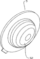
Fig. 2 is a backwater working state section perspective view embodiment illustrated in fig. 1;
Fig. 3 is that backwater working state embodiment illustrated in fig. 1 is looked up structural representation;
Fig. 4 is the stereo amplification figure of middle valve body embodiment illustrated in fig. 1;
Fig. 5 is the three-dimensional structure diagram of the flange position on the middle outlet pipe outer wall embodiment illustrated in fig. 1;
Another embodiment's water flowing working state side-looking generalized section of Fig. 6 the utility model threeway back-water valve (BWV);
The stereo amplification figure of valve body during Fig. 7 is embodiment illustrated in fig. 6;
Fig. 8 the utility model threeway back-water valve (BWV) is another embodiment's water flowing working state side-looking generalized section again;
The stereo amplification figure of valve body during Fig. 9 is embodiment illustrated in fig. 8
The embodiment of a kind of application of Figure 10 the utility model threeway back-water valve (BWV).
The 1-water intake, 2-water outlet, 3-drain opening, 31-waste pipe, 32-flange plate, the 33-flange, 34-mounting hole, 4-cavity, 5-valve body, the peak of 501-waste pipe mouth of pipe face, the minimum point of 502-waste pipe mouth of pipe face, 51, the 52-projection, 6-valve, 7-water closet pan, 8-water-storing tank.
Embodiment
According to shown in Fig. 1 to 5, a kind of threeway back-water valve (BWV) comprises a cavity 4; The top of described cavity 4 is provided with the water outlet 2 that connects outlet pipe; The bottom of described cavity 4 is provided with the water intake 1 that connects intake pipe, is fixed on the drain opening 3 that connects waste pipe 31 on the sidewall of described cavity 4; Also comprise a valve body 5, an edge of described valve body 5 hingedly is installed on described cavity 4 inside, and the articulating point of described valve body 5 is on the described cavity 4 between described water intake 1 and the described drain opening 3.Described drain opening 3 is made of the end that waste pipe 31 stretches in the described cavity 4; Described drain opening 3 is positioned at described cavity 4 bottoms, closes on described water intake 1 place; Described water intake 1, described water outlet 2 and described drain opening 3 at grade, and described water outlet 2 and described drain opening 3 are respectively in the both sides of described water intake 1 axis.Described water outlet 2 is equal with the upper and lower bottom surface of described cavity 4 respectively with described water intake 1, the inclination that faces down of waste pipe 31 mouths of pipe of connecting described drain opening 3 places, be suitable for described valve body 5 surface engagement with described drain opening 3 sealings.Described valve body 5 is provided with and is beneficial to described valve body 5 and opens the balancing weight that direction moves to described drain opening 3.As shown in Figure 1 and Figure 4, described balancing weight is a projection 51 at the cone shape of described valve body 5 lower surfaces, the circular cone bottom surface be slightly larger than described water intake 1, described protruding 51 are suitable for utilizing the gravity of self that described drain opening 3 is opened.When the described water intake 1 of valve body 5 sealing, conical protrusions 51 gets lodged in the described water intake 1, referring to Fig. 2 and state shown in Figure 3.In order to make the inclination that faces down of the mounted waste pipe mouth of pipe, predetermined upper and lower quadrant position at described waste pipe 31 outer walls is provided with raised flanges 33 (in the utility model, described upper and lower quadrant position is meant on the circumferencial direction of described waste pipe 31 vertically, with peak 501 and the minimum point 502 corresponding positions of stretching into waste pipe mouth of pipe face downward-sloping in the described cavity 4), as shown in Figure 5, form mounting hole 34 respectively on the described raised flanges 33, form tapped blind hole on the outer wall of corresponding described cavity 4; By the screw that passes described mounting hole 34 waste pipe 31 is fixedly attached on the described cavity 4.Flange 32 has played the effect that prompting is installed like this, waste pipe 31 stretches into the true dip direction of the part mouth of pipe face of cavity 4 after guaranteeing just can determine installation when described cavity 4 outside installations, thereby can realize the described mouth of pipe face down tilt with the described valve body 5 surfaces described drain opening 3 of incompatible sealing that matches, the waste pipe 31 after therefore installing can well adhere to specification.
The working procedure of present embodiment is: during water flowing, the current that have certain pressure flow into from water intake 1, and valve body 5 is impacted the position of the waste pipe mouth of pipe, drain opening 3 is closed under the impact of current, because at this moment valve body 5 is in the position near the waste pipe mouth of pipe, referring to state shown in Figure 1, water impact is behind valve body 5, the direction skew of flowing is to water intake 1 axis right side, because water outlet 2 is positioned at cavity 5 upper bottom surface right-hand members, current can flow out from water outlet 2 smoothly, and described water outlet 2 and described drain opening 3 have guaranteed the unimpeded of water route respectively in the both sides of described water intake 1 axis.When the water flowing process finished the beginning backwater, water intake 1 was no longer intake, and valve body 5 no longer is subjected to the impact of current.Because the waste pipe mouth of pipe faces down and tilts and under the acting in conjunction of balancing weight conical protrusions 51, valve body 5 leaves the waste pipe nozzle position, water outlet 1 place of backwater mean place falls, tapered protrusion 51 falls into water intake 1, valve body 5 under the pressure of gravity of self and the current that fall back with water intake 1 sealing, referring to Fig. 2 and state shown in Figure 3, at this moment the ducted water that is higher than water outlet 1 falls, and flow out the threeway back-water valve (BWV)s, thereby finish the working procedure of a water flowing, backwater by the drain opening of having opened 3.Present embodiment utilizes the gravity of impact force of water flow and valve body 5 self to finish the conducting and the sealing in water route in the course of the work, need not manually-operable can discharge conduit in ponding, prevent that pipeline from freezing, easy to use.
The mode of execution of a kind of replacement of the foregoing description as shown in Figure 6 and Figure 7, waste pipe 31 mouth of pipe faces of connecting described drain opening 3 places are in vertical plane, described balancing weight for described valve body 5 lower surfaces be shaped as one hemispheric protruding 52, described protruding 52 weight is suitable for described drain opening 3 is opened.In the present embodiment, valve body 5 can turn to respectively vertically and two positions of level, with drain opening 2 and water intake 1 sealing.Projection 52 shapes of the lower surface of described valve body 5 match with water intake 1, when water intake 1 is no longer intake, valve body 5 falls to horizontal position in the action of gravity of hemispherical projections 52, drain opening 3 is opened, projection 52 falls into water intake 1 simultaneously, with water intake 1 sealing, ducted water is flowed out by the drain opening 3 of having opened.The working procedure of present embodiment is identical to embodiment's working procedure shown in Figure 5 with Fig. 1, is not giving unnecessary details at this.
Fig. 8 and Fig. 9 have shown Fig. 1 to another alternative again embodiment illustrated in fig. 5, and valve body 5 is a plane valve plate, and its size is suitable for respectively with water intake 1 and drain opening 3 sealings.The inclination because the waste pipe mouth of pipe faces down, the gravity of described valve body 5 dependence itself promptly can be turned to water intake 1 place, realizes water intake 1 sealing; As shown in Figure 8, on described waste pipe 31 outer walls, be set with flange plate 32; Form mounting hole 34 on the described flange plate 32, form tapped blind hole on the outer wall of corresponding described cavity 4; By the screw that passes described mounting hole 34 waste pipe 31 is fixedly attached on the described cavity 4.This flange connection structure is firm, can resist high hydraulic pressure, and the mounting hole that is provided with in the fixed position has also played the effect that prompting is installed, waste pipe 31 stretches into the true dip direction of the part mouth of pipe face of cavity 4 after guaranteeing just can determine to install when described cavity 4 outside installations, thus can realize the described mouth of pipe face down inclination with the described valve body 5 surfaces described drain opening 3 of incompatible sealing that matches.The working procedure of present embodiment is identical to embodiment's working procedure shown in Figure 5 with Fig. 1, is not giving unnecessary details at this.
In the above-described embodiments, described water intake 1, water outlet 2 and drain opening 3 also can not be arranged on the same plane, and the threeway back-water valve (BWV) can play the effect of water flowing, backwater equally; Needs according to threeway back-water valve (BWV) work water pressure, intake pipe, waste pipe and outlet pipe can be switched on the cavity with the ways of connecting that is spirally connected or weld by flange, to adapt to different hydraulic pressure working environments, because the Placement of water pipe and cavity is not invention main points of the present utility model, does not give unnecessary details in an embodiment.
Figure 10 has shown that the utility model is applied in a kind of mode of execution in the flushing unit, and the water intake 1 of threeway back-water valve (BWV) is connected the network of rivers from the beginning under the control of valve 6, and water outlet 2 is connected the flush pipe of water closet pan 7, and drain opening 3 is connected water-storing tank 8.Valve 6 can be that manually operated valve also can be two solenoid valves, and its control end setting on the ground.When valve 6 is opened, the back-water valve (BWV) of flow direction threeway from the beginning dashes described valve body 5, thereby described water intake 1 is opened, and with described drain opening 3 sealings, threeway this moment back-water valve (BWV) is with water intake 1 and water outlet 2 conductings simultaneously, current flow out the threeway back-water valve (BWV) by water outlet 2, and water closet pan 7 is washed; After flushing finishes, close described valve 6, described valve body 5 seals described water intake 1 under action of gravity, and make described drain opening 3 open, threeway this moment back-water valve (BWV) is with water outlet 2 and drain opening 3 conductings, and ducted water is flowed in the water-storing tank 8 by drain opening 3, thereby has finished the once process of bath, backwater, the not water of guaranteeing to flush the toilet in the pipeline, thus the antifreeze of lavatory toilet-flushing apparatus guaranteed.The water that flow into the described water-storing tank 8 from described drain opening 3 can carry out second use.The flushing unit of present embodiment is with valve 6 control water-rinsing processes, and is simple, convenient, and water waste water resource not again neither in the pipeline has well played the effect of anti-freezing economical.
Obviously, the foregoing description only is for example clearly is described, and is not the qualification to mode of execution.For those of ordinary skill in the field, can also make other changes in different forms on the basis of the above description.Here need not also can't give exhaustive to all mode of executions.And conspicuous variation of being extended out thus or change still are among the protection domain of claims that the utility model creates.
Claims (8)
1. a threeway back-water valve (BWV) comprises a cavity (4); The top of described cavity (4) is provided with the water outlet (2) that connects outlet pipe; The bottom of described cavity (4) is provided with the water intake (1) that connects intake pipe, is fixed on the drain opening (3) that connects waste pipe on the sidewall of described cavity (4);
It is characterized in that:
Also comprise a valve body (5), one edge of described valve body (5) hingedly is installed on described cavity (4) inside, and the diverse location in rotatable scope, utilize the gravity of described valve body (5) self that described drain opening (3) is opened respectively, or be used to described drain opening (3) be sealed from described water intake (1) impact force of water flow.
2. threeway back-water valve (BWV) according to claim 1 is characterized in that: described drain opening (3) is made of the end that waste pipe (31) stretches in the described cavity (4); Described drain opening (3) is positioned at described cavity (4) bottom, closes on described water intake (1) and locates; The articulating point of described valve body (5) is positioned on the described cavity (4) between described water intake (1) and the described drain opening (3).
3. threeway back-water valve (BWV) according to claim 2 is characterized in that: connect waste pipe (31) mouth of pipe that described drain opening (3) locates face down tilt to be suitable for described valve body (5) surface engagement so that described drain opening (3) is sealed.
4. according to any described threeway back-water valve (BWV) among the claim 1-3, it is characterized in that: described valve body (5) is provided with and is beneficial to described valve body (5) and opens the balancing weight that direction moves to described drain opening (3).
5. threeway back-water valve (BWV) according to claim 4 is characterized in that: described balancing weight for described valve body (5) lower surface be shaped as a projection (51,52), described projection (51,52) is suitable for described water intake (1) is sealed.
6. according to any described threeway back-water valve (BWV) among the claim 1-3, it is characterized in that: described water intake (1), described water outlet (2) and described drain opening (3) at grade, and described water outlet (2) and described drain opening (3) are respectively in the both sides of described water intake (1) axis.
7. threeway back-water valve (BWV) according to claim 2 is characterized in that: be set with flange plate (32) on described waste pipe (31) outer wall; Form mounting hole (34) on the described flange plate (32), form tapped blind hole on the outer wall of corresponding described cavity (4); By the screw that passes described mounting hole (34) waste pipe (31) is fixedly attached on the described cavity (4).
8. threeway back-water valve (BWV) according to claim 2, it is characterized in that: the predetermined last lower quadrant position at described waste pipe (31) outer wall is provided with raised flanges (33), form mounting hole (34) on the described raised flanges (33) respectively, form tapped blind hole on the outer wall of corresponding described cavity (4); By the screw that passes described mounting hole (34) waste pipe (31) is fixedly attached on the described cavity (4).
Priority Applications (1)
| Application Number | Priority Date | Filing Date | Title |
|---|---|---|---|
| CNU2008201330066U CN201250921Y (en) | 2008-07-29 | 2008-07-29 | Three-way backwater water valve |
Applications Claiming Priority (1)
| Application Number | Priority Date | Filing Date | Title |
|---|---|---|---|
| CNU2008201330066U CN201250921Y (en) | 2008-07-29 | 2008-07-29 | Three-way backwater water valve |
Publications (1)
| Publication Number | Publication Date |
|---|---|
| CN201250921Y true CN201250921Y (en) | 2009-06-03 |
Family
ID=40746594
Family Applications (1)
| Application Number | Title | Priority Date | Filing Date |
|---|---|---|---|
| CNU2008201330066U Expired - Fee Related CN201250921Y (en) | 2008-07-29 | 2008-07-29 | Three-way backwater water valve |
Country Status (1)
| Country | Link |
|---|---|
| CN (1) | CN201250921Y (en) |
Cited By (8)
| Publication number | Priority date | Publication date | Assignee | Title |
|---|---|---|---|---|
| CN106480956A (en) * | 2016-11-16 | 2017-03-08 | 山东农业大学 | The antifreeze flushing system of lavatory |
| CN108487413A (en) * | 2018-03-30 | 2018-09-04 | 天津市管道工程集团有限公司 | The sewage pipe and its installation method of energy water conservancy diversion |
| CN109114273A (en) * | 2018-09-28 | 2019-01-01 | 苏州丹顿机电有限公司 | One kind is cut off the water latching valve |
| CN110905048A (en) * | 2018-09-16 | 2020-03-24 | 管凤强 | An underground antifreeze water supply device |
| CN112939345A (en) * | 2021-01-29 | 2021-06-11 | 重庆工商大学 | Intelligent sewage treatment device and method |
| CN112984176A (en) * | 2021-04-22 | 2021-06-18 | 重庆市渝水水务机械有限公司 | Automatic water discharge valve for fire hydrant residual water |
| CN113605056A (en) * | 2020-10-26 | 2021-11-05 | 松下家电(中国)有限公司 | Backstop device of clothes treatment equipment and clothes treatment equipment |
| CN116585128A (en) * | 2023-05-19 | 2023-08-15 | 成都联帮医疗科技股份有限公司 | A micro-pressure soft oxygen chamber |
-
2008
- 2008-07-29 CN CNU2008201330066U patent/CN201250921Y/en not_active Expired - Fee Related
Cited By (11)
| Publication number | Priority date | Publication date | Assignee | Title |
|---|---|---|---|---|
| CN106480956A (en) * | 2016-11-16 | 2017-03-08 | 山东农业大学 | The antifreeze flushing system of lavatory |
| CN108487413A (en) * | 2018-03-30 | 2018-09-04 | 天津市管道工程集团有限公司 | The sewage pipe and its installation method of energy water conservancy diversion |
| CN108487413B (en) * | 2018-03-30 | 2024-03-12 | 天津市管道工程集团有限公司 | Sewage drainage pipeline capable of guiding flow and installation method thereof |
| CN110905048A (en) * | 2018-09-16 | 2020-03-24 | 管凤强 | An underground antifreeze water supply device |
| CN109114273A (en) * | 2018-09-28 | 2019-01-01 | 苏州丹顿机电有限公司 | One kind is cut off the water latching valve |
| CN109114273B (en) * | 2018-09-28 | 2020-06-30 | 苏州丹顿机电有限公司 | Self-locking valve for water cut-off |
| CN113605056A (en) * | 2020-10-26 | 2021-11-05 | 松下家电(中国)有限公司 | Backstop device of clothes treatment equipment and clothes treatment equipment |
| CN113605056B (en) * | 2020-10-26 | 2025-11-04 | 松下家电(中国)有限公司 | Anti-reverse device for garment processing equipment and garment processing equipment |
| CN112939345A (en) * | 2021-01-29 | 2021-06-11 | 重庆工商大学 | Intelligent sewage treatment device and method |
| CN112984176A (en) * | 2021-04-22 | 2021-06-18 | 重庆市渝水水务机械有限公司 | Automatic water discharge valve for fire hydrant residual water |
| CN116585128A (en) * | 2023-05-19 | 2023-08-15 | 成都联帮医疗科技股份有限公司 | A micro-pressure soft oxygen chamber |
Similar Documents
| Publication | Publication Date | Title |
|---|---|---|
| CN201250921Y (en) | Three-way backwater water valve | |
| CN110258728B (en) | A flat tube front floor drain type non-drop floor same-floor drainage system | |
| CN102330453B (en) | Access apparatus of pipeline for anti-back overflow | |
| CN205917828U (en) | Distribution of rain and sewage auto -change over device | |
| CN212130548U (en) | Tunnel drainage system capable of preventing and treating karst water crystallization | |
| CN208792438U (en) | A kind of double standpipes band water seal is from ventilation draining sub-assembly | |
| CN201250441Y (en) | Water-saving and antifreezing toilet-flushing system | |
| CN102330452B (en) | Overflow-proof same-layer water drainage riser connecting piece | |
| CN201334713Y (en) | Water-saving anti-freeze toilet flushing system | |
| CN202000419U (en) | Simple same floor drainage system | |
| CN218116700U (en) | A construction site water auxiliary system | |
| CN202577498U (en) | Deodorizing sewer pipe | |
| CN110359519A (en) | A kind of antifreezing water-saving type flush toilet system | |
| CN207582227U (en) | A kind of improved road surface drainage device | |
| CN201424694Y (en) | Water-saving anti-freezing flushing system | |
| CN211113991U (en) | Pipe hanging type sewage intercepting pipeline | |
| CN209523279U (en) | Structure that rainwater and sewage reposition of redundant personnel and piping lane combined together | |
| CN204059578U (en) | Water tank turnover panel rinses door | |
| CN102330458B (en) | Pipeline connection device for preventing overflow return and sludge | |
| CN201598683U (en) | Building same-floor water drainage effluent segregation mounting system | |
| CN210288913U (en) | A siphon roof drainage structure | |
| CN209723099U (en) | A kind of Intelligent type antifreezing bath public lavatory | |
| CN212801777U (en) | Underground anti-freezing water supply device | |
| CN112431282A (en) | Pre-buried formula drainage concentrator of ventilating | |
| CN109577471A (en) | A kind of autocontrol municipal drainage pipe network dredging device and its control method |
Legal Events
| Date | Code | Title | Description |
|---|---|---|---|
| C14 | Grant of patent or utility model | ||
| GR01 | Patent grant | ||
| CF01 | Termination of patent right due to non-payment of annual fee |
Granted publication date: 20090603 Termination date: 20160729 |
|
| CF01 | Termination of patent right due to non-payment of annual fee |