CN201284673Y - Mechanical distribution type dual-mode engine air valve timing variable system - Google Patents
Mechanical distribution type dual-mode engine air valve timing variable system Download PDFInfo
- Publication number
- CN201284673Y CN201284673Y CNU2008201423018U CN200820142301U CN201284673Y CN 201284673 Y CN201284673 Y CN 201284673Y CN U2008201423018 U CNU2008201423018 U CN U2008201423018U CN 200820142301 U CN200820142301 U CN 200820142301U CN 201284673 Y CN201284673 Y CN 201284673Y
- Authority
- CN
- China
- Prior art keywords
- oil
- camshaft
- valve timing
- distribution plate
- hydraulic
- Prior art date
- Legal status (The legal status is an assumption and is not a legal conclusion. Google has not performed a legal analysis and makes no representation as to the accuracy of the status listed.)
- Expired - Lifetime
Links
Images


Classifications
-
- Y—GENERAL TAGGING OF NEW TECHNOLOGICAL DEVELOPMENTS; GENERAL TAGGING OF CROSS-SECTIONAL TECHNOLOGIES SPANNING OVER SEVERAL SECTIONS OF THE IPC; TECHNICAL SUBJECTS COVERED BY FORMER USPC CROSS-REFERENCE ART COLLECTIONS [XRACs] AND DIGESTS
- Y02—TECHNOLOGIES OR APPLICATIONS FOR MITIGATION OR ADAPTATION AGAINST CLIMATE CHANGE
- Y02T—CLIMATE CHANGE MITIGATION TECHNOLOGIES RELATED TO TRANSPORTATION
- Y02T10/00—Road transport of goods or passengers
- Y02T10/10—Internal combustion engine [ICE] based vehicles
- Y02T10/12—Improving ICE efficiencies
Landscapes
- Valve Device For Special Equipments (AREA)
Abstract
本实用新型公开一种机械分配式的两模式发动机气门正时可变系统,包括有:液压挺杆总成,所述的液压挺杆总成一端的顶端压有气门摇臂,另一端连接凸轮轴,所述的凸轮轴由发动机驱动,还设置有驱动液压挺杆总成伸缩的液压驱动系统和油路分配盘,所述的液压驱动系统是通过分配盘驱动液压挺杆总成,所述的凸轮轴还连接分配盘并控制其导通。本实用新型结构简单安全方便,元件的使用寿命长,成本低,易于实现技术的产业化,系统的功耗小,可以单独控制进气门正时或单独控制排气门正时,也可以根据需要同时实现进、排气门正时的调整,只需要多加一个分配盘即可实现,进气门晚关可以实现米勒循环,提高发动机效率并降低排放,实现了可变废气涡轮增压的功能。
The utility model discloses a mechanically distributed two-mode variable engine valve timing system, which comprises: a hydraulic tappet assembly, the top of one end of the hydraulic tappet assembly is pressed with a valve rocker arm, and the other end is connected with a cam shaft, the camshaft is driven by the engine, and is also equipped with a hydraulic drive system and an oil circuit distribution plate for driving the hydraulic lifter assembly to expand and contract. The hydraulic drive system drives the hydraulic lifter assembly through the distribution plate. The camshaft is also connected to the distribution plate and controls its conduction. The utility model has the advantages of simple, safe and convenient structure, long service life of components, low cost, easy realization of industrialization of technology, low power consumption of the system, independent control of intake valve timing or exhaust valve timing, or according to It is necessary to adjust the timing of the intake and exhaust valves at the same time, and it only needs to add an additional distribution plate. The late closing of the intake valve can realize the Miller cycle, improve engine efficiency and reduce emissions, and realize the variable exhaust gas turbocharging. Function.
Description
技术领域 technical field
本实用新型涉及一种内燃机气门正时与升程可变系统。特别是涉及一种可分别对进、排气门进行正时调整的机械分配式的两模式发动机气门正时可变系统。The utility model relates to a valve timing and lift variable system of an internal combustion engine. In particular, it relates to a mechanically distributed two-mode engine valve timing variable system that can adjust the timing of intake and exhaust valves respectively.
背景技术 Background technique
20世纪80年代以来,能源和环境问题日益突出,社会对燃油的经济性和有害排放物的要求日益严格,如何改善发动机的性能、提高热效率和减少有害排放越来越受到关注,这就要求对传统发动机进行改进。Since the 1980s, energy and environmental issues have become increasingly prominent, and society has increasingly strict requirements on fuel economy and harmful emissions. How to improve engine performance, increase thermal efficiency and reduce harmful emissions has attracted more and more attention. Improved conventional engines.
发动机的配气相位对燃烧过程的优劣起着至关重要的作用。配气相位的选择要考虑到发动机的高速功率、低速扭矩、怠速油耗、部分负荷下的燃油经济性、低速平稳性和废气排放等问题。传统的活塞式四冲程发动机普遍采用机械式凸轮轴驱动进气门和排气门的配气机构。气门的运动通过曲轴与凸轮轴,凸轮轴与各气门之间的机械传动来控制定时。这种机械式机构被证明是简单、有效和可靠的,并且费用相对低廉。然而,这种气门机构在气门的开启时刻,开启持续时间和气门升程等参数上是固定不变的,无法在发动机运行中进行调节,工作缺乏柔性。而这些固定不变的气门运行参数不能在各种情况下提供最佳正时,发动机性能潜力不能得到充分发挥。对配气时间进行一定改变,能满足内燃机大部分工况的基本要求,所以被认为是可行的。为了获得较好的发动机性能,配气相位应随着转速和负荷的变化而变化。发动机在高速和大负荷下需要较大的气门重叠角和进气门关闭角,以便得到较高的功率输出;反之,在怠速和低速小负荷下则需要较小的进气门关闭角和气门重叠角,以便得到较好的怠速平稳性和废气排放性能。The valve timing of the engine plays a vital role in the quality of the combustion process. The selection of valve timing should take into account the engine's high-speed power, low-speed torque, idling fuel consumption, fuel economy under partial load, low-speed stability and exhaust emissions. Traditional piston four-stroke engines generally use a mechanical camshaft to drive the valve train of the intake and exhaust valves. The movement of the valves is controlled by the mechanical transmission between the crankshaft and the camshaft, and between the camshaft and each valve. This mechanical mechanism has proven to be simple, efficient, reliable and relatively inexpensive. However, this valve mechanism is fixed in parameters such as the opening moment of the valve, the opening duration and the valve lift, and cannot be adjusted during engine operation, and the work lacks flexibility. However, these fixed valve operating parameters cannot provide the best timing under various conditions, and the engine performance potential cannot be fully utilized. A certain change to the gas distribution time can meet the basic requirements of most working conditions of the internal combustion engine, so it is considered feasible. In order to obtain better engine performance, the valve timing should be changed with the change of speed and load. The engine needs a larger valve overlap angle and intake valve closing angle at high speed and heavy load in order to obtain higher power output; conversely, at idle speed and low speed and small load, a smaller intake valve closing angle and valve closing angle are required. Overlap angle for better idling smoothness and exhaust emission performance.
发动机工作者针对减少发动机有害排放物改进了发动机的设计,改良了发动机的控制系统,出现了废气再循环(EGR)和后处理技术,然而伴随着发动机有害排放物的减少,却导致了发动机效率的降低,而当采用高增压压力时可能导致发动机最高爆发压力过高。可变配气技术可以通过改变气门开启关闭时刻实现米勒循环,在发动机运行的一定工况下,可以利用延迟进气门关闭的时间,使一部分已经进入气缸的气体重新进入进气歧管,并在涡轮增压的作用下保持一定的气压,发动机的进气效率可以大大增加并降低泵吸损失。这样就造成了实际上的压缩空气没有进气时的多从而降低压缩比,造成膨胀比大于压缩比,减小发动机工作的最高爆发压力。Engine workers have improved the design of the engine to reduce the harmful emissions of the engine, improved the control system of the engine, and appeared exhaust gas recirculation (EGR) and after-treatment technology. However, with the reduction of harmful emissions from the engine, it has led to engine efficiency , and when high boost pressure is used, it may cause the maximum engine burst pressure to be too high. The variable valve distribution technology can realize the Miller cycle by changing the opening and closing time of the valve. Under certain operating conditions of the engine, it can be used to delay the closing time of the intake valve so that part of the gas that has entered the cylinder can re-enter the intake manifold. And by maintaining a certain air pressure under the action of turbocharging, the intake efficiency of the engine can be greatly increased and the pumping loss can be reduced. In this way, the actual compressed air is not as much as the intake air, thereby reducing the compression ratio, causing the expansion ratio to be greater than the compression ratio, and reducing the maximum explosion pressure of the engine.
与固定配气相位相比,可变配气相位则可以在发动机不同工作范围内的转速和负荷下,提供可变的气门开启、关闭时刻或升程,从而改善发动机进、排气性能,较好的满足发动机在高转速与低转速、大负荷与小负荷时动力性、经济性、废气排放的要求,整体提高发动机综合性能。现代高科技的发展已将汽车发动机的节能、增效、低排放作为“节能—高效—环保”一体化课题进行综合研究和技术开发。配气相位固定不变的限制Compared with the fixed valve timing, the variable valve timing can provide variable valve opening and closing timing or lift under the engine speed and load in different working ranges, thereby improving the engine intake and exhaust performance, and better It satisfies the requirements of power, economy and exhaust emission of the engine at high speed and low speed, high load and small load, and improves the comprehensive performance of the engine as a whole. The development of modern high technology has taken the energy saving, efficiency enhancement and low emission of automobile engines as an integrated subject of "energy saving-high efficiency-environmental protection" for comprehensive research and technical development. The limitation of fixed valve timing
已越来越显得不适应时代要求,为此,可变气门技术已成为汽车发动机研究重点方向之一。It has become more and more incompatible with the requirements of the times. For this reason, variable valve technology has become one of the key research directions of automobile engines.
可变配气技术由于自身的优点,日益受到人们的重视,国外研究机构进行了大量的研究,出现了很多种可变气门驱动机构,有些系统实现了气门参数可变的功能,但只有少数结构简单、成本较低的机构实现了产品化,大多数可变气门驱动机构由于成本较高或者可靠性的问题,仅处于实验阶段。现有产品中的可变配气机构以改变凸轮轴的相位为主要方式,对原发动机的改动都比较大,多见于小功率汽油机。由于大功率柴油机进排气凸轮轴分为“顶置”和“侧底置”两种,由于“侧底置”凸轮轴使发动机结构简单,制造成本低,目前应用十分广泛,通常它的进排气门由同一凸轮轴驱动,很难使进排气门分别进行调整,所以大功率柴油机的可变气门技术有待开发。Due to its own advantages, variable valve distribution technology has been paid more and more attention by people. Foreign research institutions have conducted a lot of research, and many kinds of variable valve drive mechanisms have appeared. Some systems have realized the function of variable valve parameters, but only a few structures Simple, low-cost mechanisms have been commercialized, and most variable valve drive mechanisms are only in the experimental stage due to high cost or reliability problems. The variable valve train in the existing products is mainly based on changing the phase of the camshaft, and the changes to the original engine are relatively large, and it is more common in low-power gasoline engines. Since the intake and exhaust camshafts of high-power diesel engines are divided into two types: "top-mounted" and "side-bottom-mounted", the "side-bottom-mounted" camshaft makes the engine structure simple and the manufacturing cost is low, so it is widely used at present. The exhaust valves are driven by the same camshaft, so it is difficult to adjust the intake and exhaust valves separately, so the variable valve technology for high-power diesel engines needs to be developed.
发明内容 Contents of the invention
本实用新型所要解决的技术问题是,提供一种。既对材料和加工设备的要求不高,对原柴油机改动小,同时工作可靠的机械分配式的两模式发动机气门正时可变系统。The technical problem to be solved by the utility model is to provide a. It has low requirements on materials and processing equipment, minor changes to the original diesel engine, and a mechanically distributed two-mode variable engine valve timing system that works reliably.
本实用新型所采用的技术方案是:一种机械分配式的两模式发动机气门正时可变系统,包括有:液压挺杆总成,所述的液压挺杆总成一端的顶端压有气门摇臂,另一端连接凸轮轴,所述的凸轮轴由发动机驱动,还设置有驱动液压挺杆总成伸缩的液压驱动系统和油路分配盘,所述的液压驱动系统是通过分配盘驱动液压挺杆总成,所述的凸轮轴还连接分配盘并控制其导通。The technical scheme adopted by the utility model is: a mechanically distributed two-mode engine valve timing variable system, including: a hydraulic lifter assembly, the top of one end of the hydraulic lifter assembly is pressed with a valve rocker The other end of the arm is connected to the camshaft. The camshaft is driven by the engine. It is also equipped with a hydraulic drive system and an oil circuit distribution plate for driving the hydraulic lifter assembly to expand and contract. The hydraulic drive system drives the hydraulic lifter through the distribution plate. Rod assembly, the camshaft is also connected to the distribution plate and controls its conduction.
所述的液压驱动系统包括有:机油箱,连接机油箱的油泵,驱动油泵的泵驱动装置和与油泵相连通的调压阀,其中,所述的调压阀还分别连接机油箱和通过分配盘的进油油路连通液压挺杆总成,所述的机油箱还连通分配盘的回油油路。The hydraulic drive system includes: an oil tank, an oil pump connected to the oil tank, a pump driving device for driving the oil pump, and a pressure regulating valve connected with the oil pump, wherein the pressure regulating valve is also connected to the oil tank and through the distribution The oil inlet circuit of the disc is connected with the hydraulic tappet assembly, and the oil tank is also connected with the oil return circuit of the distribution disc.
所述的油泵为齿轮泵、柱塞泵、转子泵及叶片泵中的一种。The oil pump is one of gear pump, plunger pump, rotor pump and vane pump.
所述的泵驱动装置是电机、机械驱动结构中的一种。The pump driving device is one of a motor and a mechanical driving structure.
所述的分配盘包括有:定盘和以定盘的中心为旋转轴的动盘,所述的定盘上沿动盘的旋转轨迹上开有多数个分别与进油油路及回油油路连通的过油孔。The distribution plate includes: a fixed plate and a moving plate with the center of the fixed plate as the rotation axis, and a plurality of oil inlet passages and oil return oil passages are opened on the fixed plate along the rotation track of the moving plate. The oil hole connected by the road.
所述的分配盘的动盘是通过连轴器连接凸轮轴,或通过与凸轮轴相连的齿轮连接凸轮轴,或通过任意的与凸轮轴有相同转速的轴或齿轮连接凸轮轴。The moving disc of the distribution disc is connected to the camshaft through a coupling, or connected to the camshaft through a gear connected to the camshaft, or connected to the camshaft through any shaft or gear having the same rotational speed as the camshaft.
所述的系统可单独控制进气门正时或单独控制排气门正时,或同时实现进、排气门正时的调整,当同时实现进、排气门正时的调整时,设置有两个与凸轮轴相连的分配盘。The system can control the timing of the intake valve or the timing of the exhaust valve alone, or realize the adjustment of the timing of the intake and exhaust valves at the same time. When the adjustment of the timing of the intake and exhaust valves is realized simultaneously, there are Two distribution discs connected to the camshafts.
本实用新型的机械分配式的两模式发动机气门正时可变系统,是由机械式分配盘控制,结构简单安全方便;对液压挺杆偶件及分配盘的加工精度及材料力学性能没有太高要求,元件的使用寿命长;可分别对进、排气门进行正时的调整;液压挺杆总成可在普通发动机现有推杆基础上进行改装,分配盘可以装在发动机凸轮轴齿轮上,对原机改动小,成本低,易于实现技术的产业化;工作压力要求不高,低压油泵所需的驱动功率小,故系统的功耗小;可同时为发动机各缸分配控制油压,各缸独立控制工作可靠;可以单独控制进气门正时或单独控制排气门正时,也可以根据需要同时实现进、排气门正时的调整,只需要多加一个分配盘即可实现;进气门晚关可以实现米勒循环,提高发动机效率并降低排放;排气门早开可以改变发动机做功和排气能量间的比率,一定程度上实现了可变废气涡轮增压的功能。The mechanically distributed two-mode engine valve timing variable system of the utility model is controlled by a mechanical distribution plate, and the structure is simple, safe and convenient; the processing accuracy and material mechanical properties of the hydraulic tappet coupler and the distribution plate are not too high The service life of the components is long; the timing of the intake and exhaust valves can be adjusted separately; the hydraulic tappet assembly can be refitted on the basis of the existing push rod of the ordinary engine, and the distribution plate can be installed on the engine camshaft gear , small changes to the original machine, low cost, and easy to realize the industrialization of technology; the working pressure is not high, and the driving power required by the low-pressure oil pump is small, so the power consumption of the system is small; it can distribute and control the oil pressure for each cylinder of the engine at the same time, The independent control of each cylinder is reliable; the timing of the intake valve or the timing of the exhaust valve can be controlled separately, and the timing of the intake and exhaust valves can also be adjusted at the same time according to the needs, only need to add an additional distribution plate to achieve; Late intake valve closing can realize the Miller cycle, improve engine efficiency and reduce emissions; early exhaust valve opening can change the ratio between engine work and exhaust energy, and realize the function of variable exhaust gas turbocharging to a certain extent.
附图说明 Description of drawings
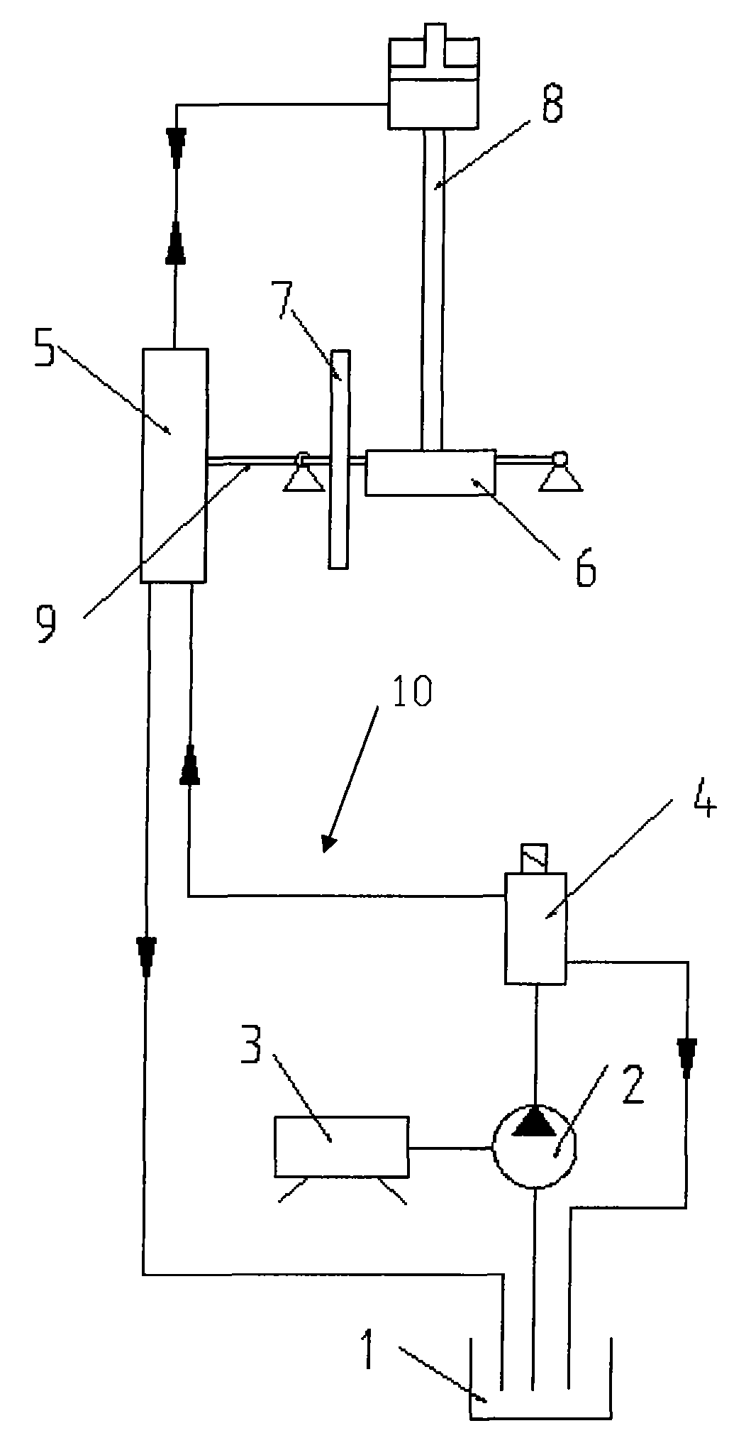
图1是本实用新型机械分配式两模式发动机气门正时可变系统的系统原理示意图;Fig. 1 is the schematic diagram of the system principle of the mechanical distribution type two-mode engine valve timing variable system of the utility model;
图2是本实用新型机械分配式两模式发动机气门正时可变系统分配盘工作原理图。Fig. 2 is a working principle diagram of the distribution plate of the mechanically distributed two-mode engine valve timing variable system of the utility model.
其中:in:
1:机油箱 2:油泵1: Oil tank 2: Oil pump
3:泵驱动装置 4:调压阀3: Pump driving device 4: Pressure regulating valve
5:分配盘 6:凸轮轴5: Distributor plate 6: Camshaft
7:正时齿轮 8:液压挺杆总成7: Timing gear 8: Hydraulic tappet assembly
9:连轴器 10:液压驱动系统9: Coupling 10: Hydraulic drive system
51:动盘 52:定盘51: Moving plate 52: Fixed plate
53:过油孔53: oil hole
具体实施方式 Detailed ways
下面结合实施例附图对本实用新型的机械分配式的两模式发动机气门正时可变系统做出详细说明。The mechanical distribution type two-mode engine valve timing variable system of the utility model will be described in detail below in conjunction with the accompanying drawings of the embodiments.
如图1所示,本实用新型的机械分配式的两模式发动机气门正时可变系统,包括有:液压挺杆总成8,所述的液压挺杆总成8一端的顶端压有气门摇臂,另一端连接凸轮轴6,所述的凸轮轴6由发动机驱动,还设置有驱动液压挺杆总成8伸缩的液压驱动系统10和油路分配盘5,所述的液压驱动系统10是通过分配盘5驱动液压挺杆总成8,所述的凸轮轴6还连接分配盘5并控制其导通。As shown in Figure 1, the mechanically distributed two-mode engine valve timing variable system of the present invention includes: a
所述的液压驱动系统10包括有:机油箱1,连接机油箱1的油泵2,驱动油泵2的泵驱动装置3和与油泵2相连通的调压阀4,其中,所述的调压阀4还分别连接机油箱1和通过分配盘5的进油油路连通液压挺杆总成8,所述的机油箱1还连通分配盘5的回油油路。所述的油泵2为齿轮泵、柱塞泵、转子泵及叶片泵中的一种。所述的泵驱动装置3是电机、机械驱动结构中的一种。The
如图2所示,所述的分配盘5包括有:定盘52和以定盘52的中心为旋转轴的动盘51,所述的定盘52上沿动盘51的旋转轨迹上开有多数个分别与进油油路及回油油路连通的过油孔53。靠动盘51和定盘52之间的相对运动实现油路的通断控制,进而实现液压挺杆总成伸长和缩短的控制。具有良好的可靠性和自密封性,可以同时满足进油和回油的分配,是为实现发动机气门正时可变系统设计的专用控制部件。As shown in Figure 2, the described distributing disk 5 includes: a fixed
所述的凸轮轴6是通过连轴器9连接分配盘5的动盘51,或通过与凸轮轴6相连的齿轮连接分配盘5的动盘51,或通过任意的与凸轮轴6有相同转速的轴或齿轮连接分配盘5的动盘51,从而实现与发动机的同步旋转。The
在本实用新型中所述的凸轮轴6位于分配盘5一侧,所述的动盘51与正时齿轮7连接。与凸轮轴6相连的正时齿轮7带动凸轮轴6和分配盘5的动盘51旋转,实现分配盘的动盘51和凸轮轴6同步旋转,从而实现气门正时可变系统的正时。The
本实用新型是靠分配盘上动盘开口的大小确定气门正时与升程可变系统一个工作循环内液压挺杆总成内进油和排油时间长短。一个分配盘可以为六个液压挺杆同时分配高压油,根据需要过油孔的个数可以不同,只需在定盘上加工不同个数的过油孔。The utility model depends on the size of the opening of the moving plate on the distribution plate to determine the length of time for oil intake and oil discharge in the hydraulic tappet assembly in a working cycle of the valve timing and variable lift system. One distribution plate can distribute high-pressure oil for six hydraulic tappets at the same time, and the number of oil passage holes can be different according to the needs, and only need to process different numbers of oil passage holes on the fixed plate.
当系统在非工作模式时,所述油泵输送的机油经调压阀直接进入机油箱,液压挺杆长度固定不变且为原机长度,所述液压挺杆总成随发动机凸轮轴旋转进行上下往复运动,使进、排气门按照原机的定时与升程进行动作。When the system is in the non-working mode, the oil delivered by the oil pump directly enters the oil tank through the pressure regulating valve, the length of the hydraulic lifter is fixed and is the original machine length, and the hydraulic lifter assembly moves up and down with the rotation of the engine camshaft The reciprocating motion makes the intake and exhaust valves move according to the timing and lift of the original machine.
当系统在工作模式时,该系统可以实现进气门晚关也可实现排气门早开。When the system is in the working mode, the system can realize the late closing of the intake valve and the early opening of the exhaust valve.
对于实现进气门晚关的情况:首先调压阀动作,系统管路里建立油压,分配盘的动盘随与凸轮轴一起旋转,当原进气门升到最高点又开始降落时的某个恰当的时刻,分配盘把进油路接通,机油经管道进入液压挺杆总成,此时液压挺杆总成的长度增加,产生一个附加升程叠加在原气门升程上。当凸轮轴继续旋转到原气门关闭点时,由于液压挺杆总成变长,气门并没有关闭,此时进入进气门晚关阶段。凸轮轴再转过一定角度,分配盘把回油油路接通,液压挺杆总成里的机油回流,液压挺杆总成变回原来长度,气门关闭。如此完成发动机的一个配气循环内进气门晚关的调整。For the situation of realizing the late closing of the intake valve: firstly, the pressure regulating valve acts, the oil pressure is established in the system pipeline, and the moving plate of the distribution disc rotates together with the camshaft. When the original intake valve rises to the highest point and starts to descend again At an appropriate moment, the distribution plate connects the oil inlet circuit, and the engine oil enters the hydraulic lifter assembly through the pipeline. At this time, the length of the hydraulic lifter assembly increases, and an additional lift is superimposed on the original valve lift. When the camshaft continues to rotate to the original valve closing point, the valve is not closed due to the lengthening of the hydraulic lifter assembly, and at this time it enters the stage of late closing of the intake valve. When the camshaft rotates through a certain angle again, the distribution plate connects the oil return circuit, the machine oil in the hydraulic lifter assembly flows back, the hydraulic lifter assembly returns to its original length, and the valve closes. In this way, the adjustment of the late closing of the intake valve in one valve cycle of the engine is completed.
对于实现排气门早开的情况:首先调压阀动作,系统管路里建立油压,分配盘的动盘随与凸轮轴相连的齿轮一起旋转,在原排气门打开之前的某个恰当的时刻,分配盘把进油路接通,机油经管道进入液压挺杆总成,此时液压挺杆总成的长度变长,排气门被提前打开。当凸轮轴继续旋转,排气门继续打开。在凸轮轴再转过一定角度,分配盘把回油油路接通,液压挺杆总成里的机油流出,液压挺杆总成变回原来长度,排气门正常关闭。如此完成发动机的一个配气循环内排气门早开的调整。For the situation of realizing the early opening of the exhaust valve: firstly, the pressure regulating valve acts, the oil pressure is established in the system pipeline, the moving plate of the distribution disc rotates together with the gear connected to the camshaft, and a proper time before the original exhaust valve opens At this time, the distribution plate connects the oil inlet circuit, and the machine oil enters the hydraulic lifter assembly through the pipeline. At this time, the length of the hydraulic lifter assembly becomes longer, and the exhaust valve is opened in advance. As the camshaft continues to rotate, the exhaust valves continue to open. When the camshaft rotates through a certain angle, the distribution plate connects the oil return circuit, the oil in the hydraulic lifter assembly flows out, the hydraulic lifter assembly returns to its original length, and the exhaust valve closes normally. In this way, the adjustment of the early opening of the exhaust valve in one valve cycle of the engine is completed.
本实用新型的机械分配式的两模式发动机气门正时可变系统,靠在油路中安装一个分配盘,靠分配盘控制油路的通断进而实现气门正时的控制。通过仔细调整分配盘上油孔的位置和大小,可以满足发动机进、排气的定时改变的要求,从而调整发动机配气到较佳状态。The mechanically distributed two-mode variable engine valve timing system of the utility model relies on installing a distribution plate in the oil circuit, and controls the on-off of the oil circuit by the distribution plate to realize the control of the valve timing. By carefully adjusting the position and size of the oil hole on the distribution plate, the timing change requirements of engine intake and exhaust can be met, so as to adjust the engine air distribution to the best state.
本实用新型的机械分配式的两模式发动机气门正时可变系统,可单独控制进气门正时或单独控制排气门正时,或同时实现进、排气门正时的调整,当同时实现进、排气门正时的调整时,设置有两个与凸轮轴6相连的分配盘。The mechanically distributed two-mode variable engine valve timing system of the utility model can control the timing of the intake valve or the timing of the exhaust valve separately, or realize the adjustment of the timing of the intake and exhaust valves at the same time. When adjusting the timing of the intake and exhaust valves, two distribution discs connected with the
Claims (7)
Priority Applications (1)
| Application Number | Priority Date | Filing Date | Title |
|---|---|---|---|
| CNU2008201423018U CN201284673Y (en) | 2008-10-09 | 2008-10-09 | Mechanical distribution type dual-mode engine air valve timing variable system |
Applications Claiming Priority (1)
| Application Number | Priority Date | Filing Date | Title |
|---|---|---|---|
| CNU2008201423018U CN201284673Y (en) | 2008-10-09 | 2008-10-09 | Mechanical distribution type dual-mode engine air valve timing variable system |
Publications (1)
| Publication Number | Publication Date |
|---|---|
| CN201284673Y true CN201284673Y (en) | 2009-08-05 |
Family
ID=40949658
Family Applications (1)
| Application Number | Title | Priority Date | Filing Date |
|---|---|---|---|
| CNU2008201423018U Expired - Lifetime CN201284673Y (en) | 2008-10-09 | 2008-10-09 | Mechanical distribution type dual-mode engine air valve timing variable system |
Country Status (1)
| Country | Link |
|---|---|
| CN (1) | CN201284673Y (en) |
Cited By (3)
| Publication number | Priority date | Publication date | Assignee | Title |
|---|---|---|---|---|
| CN101929365A (en) * | 2010-07-30 | 2010-12-29 | 天津大学 | Diesel Engine Hydraulic Adaptive Valve Timing Variable System and Control Method |
| CN101418709B (en) * | 2008-10-09 | 2011-11-02 | 天津大学 | Distribution plate controlled two-mode engine valve timing changing system |
| CN104295333B (en) * | 2013-07-16 | 2017-02-22 | 张珊 | Engine valve mechanism |
-
2008
- 2008-10-09 CN CNU2008201423018U patent/CN201284673Y/en not_active Expired - Lifetime
Cited By (4)
| Publication number | Priority date | Publication date | Assignee | Title |
|---|---|---|---|---|
| CN101418709B (en) * | 2008-10-09 | 2011-11-02 | 天津大学 | Distribution plate controlled two-mode engine valve timing changing system |
| CN101929365A (en) * | 2010-07-30 | 2010-12-29 | 天津大学 | Diesel Engine Hydraulic Adaptive Valve Timing Variable System and Control Method |
| CN101929365B (en) * | 2010-07-30 | 2012-07-04 | 天津大学 | Hydraulic self-adaption air valve correct-timing variable system of diesel engine and control method thereof |
| CN104295333B (en) * | 2013-07-16 | 2017-02-22 | 张珊 | Engine valve mechanism |
Similar Documents
| Publication | Publication Date | Title |
|---|---|---|
| CN101929365B (en) | Hydraulic self-adaption air valve correct-timing variable system of diesel engine and control method thereof | |
| CN201162550Y (en) | Diesel engine electro-hydraulic control variable gas distribution device | |
| US6237551B1 (en) | Multi-cylinder diesel engine with variable valve actuation | |
| US11111825B1 (en) | Hydraulic valve mechanism with variable valve opening times and internal combustion engine | |
| CN101377138A (en) | Sliding valve type two-mode engine intake valve delaying shutdown system | |
| CN101201009A (en) | Engine valve timing and lift continuously variable system | |
| CN102383892A (en) | Variable air valve lift mechanism of internal combustion engine | |
| CN103628943B (en) | An Intensive Multifunctional Continuously Variable Valve Drive System for 4-Cylinder Internal Combustion Engine | |
| CN201284673Y (en) | Mechanical distribution type dual-mode engine air valve timing variable system | |
| CN100410513C (en) | A gas distribution system for an internal combustion engine with continuously variable gas distribution timing | |
| CN222615416U (en) | Valve mechanism for realizing backflow type cylinder deactivation of engine and engine | |
| CN202866918U (en) | Variable valve stroke mechanism of engine | |
| CN201314249Y (en) | Two-stage engine intake valve delay closing system controlled by slide valve | |
| CN110985156B (en) | Full-variable liquid valve system with buffering function | |
| CN101418709A (en) | Distribution plate controlled two-mode engine valve timing changing system | |
| CN101363337B (en) | Variable valve lift valve actuating mechanism | |
| CN201225183Y (en) | Cam axle and engine used thereby | |
| CN107401452B (en) | Turbocharged engine assembly | |
| CN103603699B (en) | An Intensive Multifunctional Continuously Variable Valve Drive System for 6-Cylinder Internal Combustion Engine | |
| CN115013108A (en) | An internal combustion engine hydraulic valve mechanism with variable opening times | |
| CN100560949C (en) | A method for improving engine idling performance | |
| CN201496115U (en) | Continuously Variable Gas Distribution Control System for Ignition Engines | |
| CN219638910U (en) | Variable exhaust valve mechanism of engine | |
| JPH11117776A (en) | Intake system for direct injection diesel engine | |
| CN112696246B (en) | A hydraulic fully variable valve mechanism and engine |
Legal Events
| Date | Code | Title | Description |
|---|---|---|---|
| C14 | Grant of patent or utility model | ||
| GR01 | Patent grant | ||
| CX01 | Expiry of patent term |
Granted publication date: 20090805 |
|
| CX01 | Expiry of patent term |