A kind of combined type vertical shaft wind turbine
Technical field:
The utility model relates to a kind of combined type vertical shaft wind turbine, specifically a kind of assembly structure that changes traditional vertical axis aerogenerator, can with modern architecture in conjunction with the vertical-shaft wind turbine installed, form distinctive brand-new building code and wind power system.
Background technique
Existing its main shaft of vertical axis aerogenerator directly is connected with the generator axle center does not have other supports, thereby the generator axle center also has the side pressure of wind-force direction except rotary torsion, also to bear fan blade, main shaft, the gravity of parts such as blade support, and vertical-axis generators be contained in the utility model framework inner main axis when under the effect of fan blade, being subjected to turned the power on its wind-force direction be dispersed on the framework, the weight of parts such as described main shaft and fan blade is born by framework of the present utility model by the bearing of described bottom, is not subjected to the influence of the power of other direction like this on the generator shaft except rotary torsion.
Existing vertical axis aerogenerator mostly is independent single use, two wind-powered electricity generation machines are in parallel to be formed duplex wind-powered electricity generation machine even can a plurality of parallel connections form " wind-powered electricity generation walls " and the utility model can allow, " the wind-powered electricity generation wall " that the utility model is made forms distinctive wind power system as being installed in the top, building, fundamentally break the pattern of the existing independent middle-size and small-size wind-powered electricity generation machine of installing, thoroughly change wind resource and utilize rule, make the wind resource at top, building obtain the exploitation of fullest!
Its generator of existing vertical-shaft wind turbine and vertical shaft are one to one, and framework of the present utility model wind-powered electricity generation machine in parallel can promote a generator jointly as linking to each other with gear, can under low wind speed environment, use.
Existing vertical-shaft wind turbine mostly is single design such as need change then design different model in addition, and its fan blade of the utility model is prefabricated into the standardized fan blade modules of various unified height, and described fan blade modules can be dissimilar (resistance type or lift-types) also can be different diameters, comes combine and assemble to satisfy the designing requirement of different heights and diameter according to power requirements and surrounding environment.
The top that existing middle-size and small-size vertical-shaft wind turbine generally is installed in building top or mountain is difficult to install at high building exterior wall, and the utility model can firmly be installed in high building exterior wall and forms distinctive high building exterior wall formula vertical axis aerogenerator promptly so-called " wind-powered electricity generation post ", and building and vertical axis aerogenerator are integrally combined becomes new building standard in future.Described " wind-powered electricity generation post " generally is installed in the exterior wall corner, as installs wind deflector additional and can increase power, and wind deflector then can provide as the wind-powered electricity generation machine of its power supply of high building billboard by self.The exterior wall formula vertical axis aerogenerator higher for building height can use reinforced design, forms " the wind-powered electricity generation post " of hypervelocity, and the combination of each section fan blade modules all has a pair of corner stent support.
Summary of the invention
A kind of combined type vertical shaft wind turbine of the utility model, purpose is to provide the fixing framework of a kind of usefulness to come supports main shaft, be connected the influence that is not subjected to the power of other direction on the generator shaft on the main shaft except rotary torsion like this, the utility model also provides a kind of standardized fan blade modules can make the wind-powered electricity generation machine of different capacity output, a plurality of wind-powered electricity generation machines are installed side by side and are formed so-called " wind-powered electricity generation wall ", and described standardized fan blade modules can also be customized to distinctive " wind-powered electricity generation post " can install high building exterior wall or corner.
The technical solution of the utility model is, a kind of vertical major of combined type vertical shaft wind turbine is equipped with framework up and down, at described framework upper and bottom bearing is housed, and the bottom be can load-bearing bearing, the bearing that vertical major is passed the bottom connects generator shaft, main shaft is installed in and makes axle center of motor only need bear the torsion of sense of rotation on the framework described in the utility model, alleviates required being subjected to force intensity and saving cost of axle center of motor greatly.The bearing that install described framework vertical major top and the bottom can be a magnetic bearing, the efficient in the time of can reducing resistance and improve low wind speed.
Described combined type vertical shaft wind turbine uses the standardized fan blade modules of unified height, and described fan blade modules can be dissimilar resistance type or the lift-types of comprising, it also can be different diameters, a plurality of fan blade modules stacks can support that as framework quite the high building exterior wall formula vertical-shaft wind turbine of height forms distinctive " wind-powered electricity generation post " with high building exterior wall or corner, it on the described high building exterior wall formula vertical-shaft wind turbine structure building building part, skin or corner reserved location are installed described wind-powered electricity generation machine as the framework of described wind-powered electricity generation machine, can be future architecture thing new standard a kind of example is provided.Described " wind-powered electricity generation post " can make full use of high-rise building wall wind resource on every side.
The fan blade modules of installing in the described wind-powered electricity generation machine frame also can mix the use resistance type and the lift-type fan blade modules improves the benefit of generator under varying environment to reach specific designing requirement.
Two of described frameworks are connected in parallel and form duplex wind-powered electricity generation machine, and a plurality of fan blades that are connected in parallel are combined to form distinctive " wind-powered electricity generation wall "; A plurality of generators can in parallel be exported, and perhaps vertical major can with gear or belt pulley is interconnected makes described a plurality of continuous vertical major use same generator.In general two wind-powered electricity generation machine sense of rotation of Xiang Lianing opposite (as with belt or chain belt pulley or sprocket wheel being linked, then two continuous wind-powered electricity generation machine sense of rotation are identical) especially have commercial value in low wind speed zone.
Wind deflector is installed in the described high building exterior wall formula vertical-shaft wind turbine outside, wind deflector can be so that 3 wind energy effectively concentrates on the fan blade modules in order to utilize wind energy that two wind deflectors also can be installed better, and wind deflector also is a billboard simultaneously, and use itself is sent.
Described its fan blade of high building exterior wall formula vertical-shaft wind turbine can be installed the LED lamp, and Xuan Zhuan fan blade itself also becomes advertisement demonstration board like this.
Described high building exterior wall formula vertical-shaft wind turbine is not reserved at the high building that has built up and is used outer wall bracket or corner support replacement framework to install under the situation of mounting point.
Described wind-powered electricity generation machine can be installed in high building wind-tunnel position, and the external frame that the structural element of high building wind-tunnel periphery can be used as described wind-powered electricity generation machine fixes installation, and generator can also be installed in the building of wind-tunnel bottom so that maintaining.
When a plurality of standardization fan blade modules of the utility model were installed on the main shaft, especially resistance type module of certain angle that need stagger between the module up and down promoted the leeward electric machine main shaft at wind-force like this and rotates more even.A plurality of fan blades that are connected in parallel are combined to form between distinctive " wind-powered electricity generation wall " main shaft as rigidity and durability with gear material as described in the continuous palpus consideration of gear.High-rise must be considered the existing building regulation limit as " wind-powered electricity generation post " is installed, the utility model will definitely produce a series of new energy efficient building standards because novel building and wind energy collection combined, and newly-built high-rise reserved location will be installed described wind-powered electricity generation machine and will be become trend in future.
Description of drawings
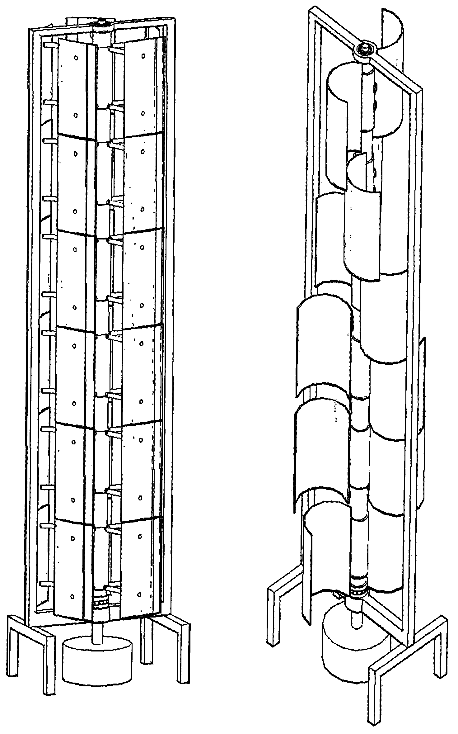
Fig. 1 is a kind of combined type vertical shaft wind turbine lift-type of the utility model and resistance type schematic appearance;
Fig. 2 is the internal structure schematic representation of a kind of combined type vertical shaft wind turbine of the utility model;
Fig. 3 adds the schematic representation that cogged connects for framework in parallel of the present utility model;
Fig. 4 is the lift-type fan blade modules shown in the utility model;
Fig. 5 is the resistance type fan blade modules shown in the utility model;
Fig. 6 is the plan view of the utility model resistance type wind-powered electricity generation machine in parallel;
Fig. 7 is the plan view of the utility model lift-type wind-powered electricity generation machine in parallel;
Fig. 8 adds the side view of cogged for the utility model lift-type wind-powered electricity generation machine in parallel;
Fig. 9 is the side view of the utility model resistance type wind-powered electricity generation machine in parallel independent generator;
Figure 10 is two groups of schematic representation that connect with 45 degree helical gears of the utility model resistance type 4 " wind-powered electricity generation wall ";
Figure 11 is the schematic representation that the utility model " wind-powered electricity generation post " uses the lift-type fan blade modules to install in the high building exterior wall corner;
Figure 12 is that the utility model " wind-powered electricity generation post " is installed the schematic representation that has wind deflector in the high building exterior wall corner;
Figure 13 is that the utility model " wind-powered electricity generation post " uses the lift-type fan blade modules that the plan view of two wind deflectors is installed in the high building exterior wall corner;
Figure 14 is the schematic representation that the utility model " wind-powered electricity generation post " uses the resistance type fan blade modules to install in the high building exterior wall corner;
Figure 15 is that the utility model " wind-powered electricity generation post " mixes the schematic representation that uses lift-type and resistance type fan blade modules to install in the high building exterior wall corner;
Figure 16 is the schematic representation of the utility model " wind-powered electricity generation post " at the two wind deflectors of the reinforced installation in high building exterior wall corner;
Figure 17 is the interior view of the utility model " wind-powered electricity generation post " at the two wind deflectors of the reinforced installation in high building exterior wall corner;
Figure 18 is installed in the mansion schematical top view for the utility model multi-joint " wind-powered electricity generation wall ";
Figure 19 is that the utility model " wind-powered electricity generation post " is installed in the schematic representation that mansion exterior wall corner and multi-joint " wind-powered electricity generation wall " are installed in the mansion top;
Figure 20 is that the utility model is at high building wind-tunnel scheme of installation;
Figure 21 is that the utility model is installed partial enlarged drawing at the high building wind-tunnel;
Figure 22 is that the utility model " wind-powered electricity generation post " is installed in the worm's eye view in the position of reserving in the building corner;
Figure 23 is that the utility model " wind-powered electricity generation post " is installed in the plan view in the position of reserving in the building corner.
Description of reference numerals
1. main shaft 12. helical gear supports
2. framework 13. belt pulleys
3. lift-type fan blade modules 14. driving belts
4. resistance type fan blade modules 15. main wall supports
5. lower bearing 16. corner supports
6. upper bearing (metal) 17. motor corner supports
7. generator 18. wind deflectors (billboard)
8. electrical axis 19. high building exterior walls
9. gear 20. high building wind-tunnel
10.45 degree helical gear 21. outer wall brackets
11. helical gear transmission part 22. buildings
Embodiment
The utility model machine lift-type and resistance type schematic appearance shown in figure (1), with main shaft (1) is that the outside, center has frame supported, main shaft (1) top has upper bearing (metal) (6) and framework (2) to cooperate assembling, there is lower bearing (5) main shaft (1) bottom as axially load-bearing bearing and framework (2) cooperate assembling, lower bearing (5) and upper bearing (metal) (6) can be respectively with magnetic bearing to reduce surface friction drag, main shaft (1) bottom is passed lower bearing (5) and is connected generator (7) by electrical axis (8).
The internal structure that lift-type fan blade modules (3) shown in figure (2) is installed, become duplex wind-powered electricity generation machine in order to increase the power parallel connection shown in the figure (3), add cogged (9) and connect adjacent main shaft, it is opposite that main shaft directly connects adjacent main axis rotation direction mutually with general type gear (9).The main shaft of wind-powered electricity generation machine in parallel can promote a generator (7) jointly as linking to each other with gear.
Lift-type fan blade modules (3) shown in figure (4); Resistance type fan blade modules (4) shown in the figure (5); Described lift-type fan blade modules (3) or resistance type fan blade modules (4) must be fixed on and make described fan blade modules can drive main shaft (1) rotation on the main shaft (1).
When a plurality of resistance type modules (4) are installed on the main shaft (1) shown in figure (6), certain angle need stagger between the module up and down, (it is 30 degree angles that Fig. 6,9,10 diagrammatic sketch apoplexy leaf modules stagger) promotes leeward electric machine main shaft (1) at wind-force like this and rotates more even.A plurality of lift-type modules (3) are installed in the plan view of main shaft (1) shown in figure (7), described lift-type module (3) angle that do not stagger.
To install belt pulley (13) additional identical with belt (14) interconnected then adjacent fan blade modules (3) sense of rotation for duplex wind-powered electricity generation machine shown in figure (8).
The side view of resistance type module (4) generator (7) output-parallel wind-powered electricity generation machine independent generator as described in shown in figure (9); Shown in figure (10) two groups in resistance type (4) connection " wind-powered electricity generation wall " with 45 degree helical gears (10) by helical gear transmission part (11) connection, helical gear transmission part (11) in general connects adjacent fan blade modules sense of rotation opposite (with reference to figure 3,6,7,9,10) with gear by helical gear support (12) fixed position.
" wind-powered electricity generation post " uses lift-type fan blade modules (3) to be installed in high building exterior wall (19) i.e. so-called " wind-powered electricity generation post " in the high building exterior wall corner shown in figure (11), in general be installed in corner effect preferable (with reference to Figure 17), replace framework with various corners support this moment, main wall angle support (15) is done main gravity and is supported, lower bearing (5) is installed on the main wall angle support (15), corner support (16) is made supplemental support upper bearing (metal) (6) and is installed on the corner support (16), and motor corner support (17) is mainly used to support generator (7) (with reference to Figure 16,17)." wind-powered electricity generation post " installed in the high building exterior wall corner and had wind deflector (18) shown in figure (12).
" wind-powered electricity generation post " uses lift-type fan blade modules (3) that two wind deflectors (18) are installed in the high building exterior wall corner shown in figure (13)." wind-powered electricity generation post " uses resistance type fan blade modules (4) to install in high building exterior wall corner (19) and is added with single wind deflector (18) simultaneously shown in figure (14), and wind deflector (18) can increase wind speed generally speaking.
" wind-powered electricity generation post " mixes the schematic representation that uses lift-type module (3) and resistance type fan blade modules (4) to install in the high building exterior wall corner shown in figure (15).
" wind-powered electricity generation post " is at the two wind deflectors of the reinforced installation in high building exterior wall corner (19) shown in figure (16), (17), figure (17) is the interior view of the two wind deflectors of the reinforced installation in high building exterior wall corner (19), " the wind-powered electricity generation post " of higher position needs to use reinforced design, and the combination of each section fan blade modules all has a pair of corner stent support respectively.For guides wind is to installing two wind deflectors (with reference to Figure 13,16,17) better, wind deflector (18) simultaneously can be as the exterior wall billboard, and the power supply of described billboard provides (with reference to Figure 19) by the utility model self electricity.
Multi-joint " wind-powered electricity generation wall " is installed in the mansion schematical top view shown in figure (18); " wind-powered electricity generation post " is installed in the schematic representation that mansion exterior wall corner and multi-joint " wind-powered electricity generation wall " are installed in the mansion top shown in figure (19).
As figure (20) high building wind-tunnel scheme of installation that is shown in; As figure (21) the high building wind-tunnel that is shown in partial enlarged drawing is installed, the utility model is installed in high building wind-tunnel (20) position, the external frame that the structural element of described high building wind-tunnel periphery can be used as the utility model wind-powered electricity generation machine fixes installation, and generator of the present utility model (7) maintaining for convenience can be installed in the building of high building wind-tunnel (20) bottom (with reference to Figure 21) in general high building wind-tunnel (20) wind speed is higher installs more powerful wind-powered electricity generation machine to make full use of wind resource.
" wind-powered electricity generation post " is installed in the worm's eye view in the position of reserving in the building corner shown in figure (22); " wind-powered electricity generation post " is installed in the plan view in the position of reserving in building (22) corner shown in figure (23).Following if any new building code, the corner of building (22) is reserved the position that is fit to and is given " wind-powered electricity generation post ", similar corner support (15), outer wall bracket (21) is used for strengthening fixing " wind-powered electricity generation post ", and building and the utility model " wind-powered electricity generation post " are integrated becomes the following Modular building thing that carries wind power system.