CN201325837Y - Self-dismounting split type turntable and crawling crane therewith - Google Patents
Self-dismounting split type turntable and crawling crane therewith Download PDFInfo
- Publication number
- CN201325837Y CN201325837Y CNU2008201764065U CN200820176406U CN201325837Y CN 201325837 Y CN201325837 Y CN 201325837Y CN U2008201764065 U CNU2008201764065 U CN U2008201764065U CN 200820176406 U CN200820176406 U CN 200820176406U CN 201325837 Y CN201325837 Y CN 201325837Y
- Authority
- CN
- China
- Prior art keywords
- turntable
- connecting seat
- self
- lower body
- upper body
- Prior art date
- Legal status (The legal status is an assumption and is not a legal conclusion. Google has not performed a legal analysis and makes no representation as to the accuracy of the status listed.)
- Expired - Lifetime
Links
Images




Landscapes
- Jib Cranes (AREA)
Abstract
Description
技术领域 technical field
本实用新型涉及履带式工程机械领域,具体涉及一种自拆装分体式转台及具有该转台的履带式起重机。The utility model relates to the field of crawler construction machinery, in particular to a self-disassembling split turntable and a crawler crane with the turntable.
背景技术 Background technique
履带式工程机械自身无法进行长距离行走转场,需要将各个部件拆解分别运输,到工地之后进行现场组装。对于具备完善的自拆装功能的履带式工程机械来说,既可以节省拆装时间,又能节约租赁辅助吊车的费用。因此,如何方便快捷地实现各主要部件的自行拆卸和组装已成为履带式工程机械的新课题。Crawler-type construction machinery cannot carry out long-distance walking and transition, and each component needs to be disassembled and transported separately, and then assembled on site after arriving at the construction site. For crawler-type construction machinery with perfect self-disassembly and assembly functions, it can not only save disassembly and assembly time, but also save the cost of renting auxiliary cranes. Therefore, how to conveniently and quickly realize the self-disassembly and assembly of each main component has become a new topic for crawler construction machinery.
随着履带式工程机械的大型化发展,履带式工程机械的各个主要部件的自重也越来越重,为适应承载的使用要求,转台的体积和重量也随之越来越大。现有大型履带式工程机械的转台采用上、下两块分体式设计,以确保可靠地完成转台的自拆装作业。如图1所示,该图是现有履带式起重机转台的整体结构示意图,其中,转台上体和转台下体通过前、后销轴(图中未示出)来实现转台的装配操作。从整个装配工艺的角度来说,增加了转台上体和转台下体的装配工序,即,完成转台的装配操作后,再进行转台与底盘之间的装配操作。With the large-scale development of crawler-type construction machinery, the weight of each main component of crawler-type construction machinery is also getting heavier. In order to meet the requirements of load-bearing use, the volume and weight of the turntable are also increasing. The turntable of the existing large-scale crawler-type construction machinery adopts an upper and lower two-piece design to ensure reliable completion of the self-disassembly and assembly operation of the turntable. As shown in Figure 1, this figure is a schematic diagram of the overall structure of the turntable of the existing crawler crane, wherein the upper body of the turntable and the lower body of the turntable realize the assembly operation of the turntable through front and rear pins (not shown in the figure). From the perspective of the entire assembly process, the assembly process of the upper body of the turntable and the lower body of the turntable is added, that is, after the assembly operation of the turntable is completed, the assembly operation between the turntable and the chassis is performed.
但是,在现有转台上体和转台下体的装配过程中,销轴与转台安装孔之间的对中完全依靠操作者目测来确定,这样就会造成装配时间较长的问题,浪费大量的人力和财力;另外,由于转台上体一直处于摆动状态,需要多个操作者密切配合操作,以避免发生人身伤害,在对中操作过程中还存在着作业安全隐患的问题。However, in the assembly process of the existing turntable upper body and turntable lower body, the alignment between the pin shaft and the turntable mounting hole is completely determined by the operator's visual inspection, which will cause the problem of long assembly time and waste a lot of time. In addition, since the upper body of the turntable is always in a swinging state, multiple operators need to cooperate closely to avoid personal injury, and there are still hidden dangers in the operation during the alignment operation.
有鉴于此,亟待研制开发出一种能够实现自动对中装配的自拆装分体式转台,以提高装配效率及作业的安全性。In view of this, it is urgent to develop a self-disassembling split turntable capable of automatic centering assembly, so as to improve assembly efficiency and operation safety.
实用新型内容Utility model content
针对上述缺陷,本实用新型解决的技术问题在于,提供一种自拆装分体式转台及具有该转台的履带式起重机。In view of the above defects, the technical problem solved by the utility model is to provide a self-detachable split turntable and a crawler crane with the turntable.
本实用新型提供的自拆装分体式转台,包括转台下体和转台上体;所述转台下体的前部具有向上伸出的第一连接附座,其后部具有向后伸出的第二连接附座;所述转台上体设置在转台下体的上方,所述转台上体具有分别与转台上体的第一连接附座和第二连接附座相连接的第三连接附座和第四连接附座;还包括第一定位部件,所述第一定位部件设置在所述转台上体第四连接附座前侧的转台下体上,所述第一定位部件的上表面与第四连接附座的下表面相抵。The self-detachable split turntable provided by the utility model includes a turntable lower body and a turntable upper body; the front part of the turntable lower body has a first connecting seat protruding upward, and its rear part has a The second connecting seat; the upper body of the turntable is arranged above the lower body of the turntable, and the upper body of the turntable has a third connecting seat connected with the first connecting seat and the second connecting seat of the upper body of the turntable respectively. The attachment seat and the fourth connection attachment seat; also include a first positioning part, the first positioning part is arranged on the lower body of the turntable on the front side of the fourth connection attachment seat of the upper body of the turntable, the first positioning part The upper surface is against the lower surface of the fourth connection seat.
优选地,所述第一定位部件的上表面为与第四连接附座的下表面相吻合的内凹弧面。Preferably, the upper surface of the first positioning component is a concave arc coincident with the lower surface of the fourth connecting seat.
优选地,所述第一定位部件为板状。Preferably, the first positioning component is plate-shaped.
优选地,还包括第二定位部件,所述第二定位部件设置在所述转台下体第二连接附座后侧的第四连接附座上,所述第二定位部件的前表面与第二连接附座的后表面相抵。Preferably, it also includes a second positioning part, the second positioning part is arranged on the fourth connecting seat on the rear side of the second connecting seat of the lower body of the turntable, and the front surface of the second positioning part is connected to the first connecting seat. The rear surfaces of the two connecting seats are offset.
优选地,所述第二定位部件前表面的下部为向后侧倾斜的导向面。Preferably, the lower part of the front surface of the second positioning component is a guide surface inclined to the rear side.
优选地,所述第二定位部件为板状。Preferably, the second positioning component is plate-shaped.
优选地,还包括第三定位部件,所述第三定位部件设置在所述转台上体第三连接附座下侧的转台下体上,所述第三定位部件的上表面与第三连接附座的下表面相抵。Preferably, a third positioning part is also included, the third positioning part is arranged on the lower body of the turntable on the lower side of the third connecting seat of the upper body of the turntable, the upper surface of the third positioning part is connected to the third connecting seat. The lower surface of the attached seat is offset.
优选地,所述第三定位部件为板状。Preferably, the third positioning component is plate-shaped.
基于现有转台上体与转台下体装配过程中存在的问题,本实用新型的设计思想是在以转台下体做为固定参照,对转台上体进行自由度约束分析的基础上建立的。众所周知,空间中可以自由运动的刚体,具有六个自由度:三个平移自由度和三个转动自由度。在转台上体和转台下体装配过程中前后两组销孔对中的情境下,仅需要约束转台上体在车体纵向平面内的自由度,即,上下平移自由度、前后平移自由度和在车体纵向平面内的转动自由度。Based on the existing problems in the assembly process of the upper body of the turntable and the lower body of the turntable, the design concept of the utility model is established on the basis of the constraint analysis of the degree of freedom of the upper body of the turntable with the lower body of the turntable as a fixed reference . As we all know, a rigid body that can move freely in space has six degrees of freedom: three translational degrees of freedom and three rotational degrees of freedom. In the situation where the upper body of the turntable and the lower body of the turntable are aligned during the assembly process of the front and rear pinholes, it is only necessary to constrain the degrees of freedom of the upper body of the turntable in the longitudinal plane of the car body, that is, the degrees of freedom of up and down translation, and the degrees of freedom of front and rear translation and rotational degrees of freedom in the longitudinal plane of the vehicle body.
本实用新型提供的自拆装分体式转台,在所述转台上体第四连接附座前侧的转台下体上增设有第一定位部件,装配时,所述转台上体的第四连接附座的下表面与第一定位部件的上表面靠紧、相抵,即可实现所述转台上体第四连接附座相对于转台上体第二连接附座在上下方向的相对位置的准确定位,可有效提高装配效率;另外,由于第四连接附座的下表面与第一定位部件靠紧就获得了相应的定位,有效规避了转台上体摆动带来的问题,因此,整个装配过程中无需要多个操作者配合操作,避免了配合失误产生人身伤害的事故发生,进而节约装配成本。In the self-detachable split turntable provided by the utility model, a first positioning part is added on the lower body of the turntable on the front side of the fourth connection seat of the upper body of the turntable. When assembling, the fourth connection of the upper body of the turntable The lower surface of the attachment seat and the upper surface of the first positioning component are close to each other, so that the accurate positioning of the relative position of the fourth connection attachment seat of the upper body of the turntable relative to the second attachment attachment seat of the upper body of the turntable in the vertical direction can be realized. , which can effectively improve the assembly efficiency; in addition, because the lower surface of the fourth connecting seat is close to the first positioning part, the corresponding positioning is obtained, which effectively avoids the problems caused by the swing of the upper body of the turntable. Therefore, during the entire assembly process There is no need for multiple operators to cooperate with the operation, avoiding accidents that cause personal injury due to coordination errors, thereby saving assembly costs.
在本实用新型的优选方案中,在所述转台下体第二连接附座后侧的转台上体上设置有第二定位部件,装配时,所述第二定位部件的前表面与第二连接附座的后表面相抵,从而实现了所述转台上体第四连接附座相对于转台上体第二连接附座在前后方向的相对位置的准确定位,进一步提高了装配效率。In a preferred solution of the present utility model, a second positioning part is arranged on the upper body of the turntable at the rear side of the second connection attachment seat of the lower body of the turntable. When assembling, the front surface of the second positioning part is aligned with the second The rear surfaces of the connecting seats are offset against each other, so as to realize accurate positioning of the relative position of the fourth connecting seat of the upper body of the turntable relative to the second connecting seat of the upper body of the turntable in the front-rear direction, further improving the assembly efficiency.
在本实用新型的另一个优选方案中,在所述转台上体第三连接附座下侧的转台下体上设置有第三定位部件。装配时,当第二连接附座与第四连接附座穿销装配完毕后,转台上体第三连接附座的下表面与所述第三定位部件的上表面相抵,这样,可实现所述转台上体相对于转台下体在车体纵向平面内的转动自由度,更进一步提高了装配效率。In another preferred solution of the present utility model, a third positioning component is arranged on the lower body of the turntable at the lower side of the third connecting seat of the upper body of the turntable. When assembling, after the second connecting seat and the fourth connecting seat are pin-assembled, the lower surface of the third connecting seat on the upper body of the turntable is against the upper surface of the third positioning part, so that the described The degree of freedom of rotation of the upper body of the turntable relative to the lower body of the turntable in the longitudinal plane of the car body further improves the assembly efficiency.
本实用新型提供的自拆装分体式转台,适用于大型履带式工程机械,特别适用于履带式起重机。The self-detachable and split turntable provided by the utility model is suitable for large-scale crawler-type engineering machinery, especially for crawler-type cranes.
本实用新型还提供了一种履带式起重机,包括转台,所述转台采用如前所述的自拆装分体式转台。The utility model also provides a crawler crane, which includes a turntable, and the turntable adopts the self-detachable split turntable as mentioned above.
附图说明 Description of drawings
图1是现有履带式起重机转台的整体结构示意图;Fig. 1 is the overall structure schematic diagram of existing crawler crane turntable;
图2是本实用新型所提供的自拆装分体式转台的转台下体的整体结构示意图;Fig. 2 is a schematic diagram of the overall structure of the lower body of the turntable of the self-detachable split turntable provided by the utility model;
图3是本实用新型所提供的自拆装分体式转台的转台上体的侧视图;Fig. 3 is a side view of the upper body of the turntable of the self-detachable split turntable provided by the utility model;
图4是图2的I部放大图;Fig. 4 is an enlarged view of part I of Fig. 2;
图5是本实用新型所述第一定位部件的主视图;Fig. 5 is a front view of the first positioning component described in the utility model;
图6是第四连接附座与第一定位部件相抵的局部侧视图;Fig. 6 is a partial side view of the fourth connecting seat against the first positioning component;
图7是图6的A-A局部剖视图;Fig. 7 is a partial sectional view of A-A of Fig. 6;
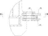
图8是图7的B-B剖视图;Fig. 8 is the B-B sectional view of Fig. 7;
图9是本实用新型所述第二定位部件的主视图;Fig. 9 is a front view of the second positioning component of the present invention;
图10是本实用新型所述自拆装分体式转台的前视图;Fig. 10 is a front view of the self-detachable split turntable of the utility model;
图11是具有本实用新型所述转台的履带式起重机的整体结构示意图。Fig. 11 is a schematic diagram of the overall structure of the crawler crane with the turntable of the present invention.
图2-图11中:In Figure 2-Figure 11:
转台下体10、第一连接附座11、第二连接附座12、第一定位部件13、焊接坡口131、第三定位部件14;Turntable
转台上体20、第三连接附座21、第四连接附座22、第二定位部件23、焊接坡口231。The
具体实施方式 Detailed ways
本实用新型是在现有分体式转台结构的基础上进行的改进设计,设计思想在于将转台下体作为固定参照物,增设了定位部件,以限定转台上体相对于转台下体的运动自由度,在装配过程中,实现了转台上体与转台下体之间的自动定位,从而提高转台的组装效率。The utility model is an improved design based on the existing split turntable structure. The design idea is to use the lower body of the turntable as a fixed reference object, and add positioning components to limit the movement of the upper body of the turntable relative to the lower body of the turntable. In the assembly process, the automatic positioning between the upper body of the turntable and the lower body of the turntable is realized, thereby improving the assembly efficiency of the turntable.
下面结合说明书附图具体说明本实施方式。The present embodiment will be described in detail below in conjunction with the accompanying drawings.
如图1所示,本实施方式所述自拆装分体式转台包括转台下体10和转台上体20;其中,转台上体20置于转台下体10的上方。As shown in FIG. 1 , the self-detachable split turntable in this embodiment includes a turntable
需要说明的是,本实用新型所提供的自拆装分体式转台的外观图与现有技术大致相同,本实施方式参照图1进行了上述内容的阐述。It should be noted that the appearance of the self-detachable split turntable provided by the utility model is substantially the same as that of the prior art, and the above-mentioned contents are described in this embodiment with reference to FIG. 1 .
请参见图2,该图是本实用新型所提供的自拆装分体式转台的转台下体的整体结构示意图。Please refer to FIG. 2 , which is a schematic diagram of the overall structure of the lower body of the turntable of the self-detachable split turntable provided by the utility model.
如图2所示,转台下体10的前部具有向上伸出的第一连接附座11,其后部具有向后伸出的第二连接附座12;其中,第一连接附座11和第二连接附座12用于实现转台下体10与转台上体20之间连接结构,第一连接附座11和第二连接附座12上均具有连接销孔。As shown in Figure 2, the front part of the turntable
请一并参见图3,该图是本实用新型所提供的自拆装分体式转台的转台上体的侧视图。Please also refer to Fig. 3, which is a side view of the upper body of the turntable of the self-detachable split turntable provided by the utility model.
如图3所示,转台上体20具有第三连接附座21和第四连接附座22。其中,第三连接附座21与转台下体10的第一连接附座11配合连接,第四连接附座22与转台下体10的第二连接附座12配合连接。第三连接附座21和第四连接附座22上均具有分别与第一连接附座11和第二连接附座12相配合的连接销孔,在装配时,当相对应的销孔轴心线对中后,插入前、后固定销轴(图中未示出)即可实现转台的组合装配。实际装配过程中,通常先进行第二连接附座12与第四连接附座22的穿销固定操作,即后销轴;再进行第一连接附座11与第三连接附座21的穿销固定操作,即前销轴。As shown in FIG. 3 , the turntable
请参见图4,该图是图2的I部放大图。Please refer to Fig. 4, which is an enlarged view of part I of Fig. 2 .
第一定位部件13设置在所述转台上体第四连接附座22前侧的转台下体10上,即设置在所述转台下体10上第二连接附座12的根部,所述第一定位部件13的上表面与第四连接附座22的下表面相抵;从而限定了第四连接附座22与第二连接附座12之间上下方向的平移自由度。The
其中,所述第一定位部件13与第四连接附座22之间的装配位置关系,请参见图6,该图为第四连接附座22与第一定位部件13相抵的局部侧视图。与连接附座的圆弧状外形相对应地,所述第一定位部件13的上表面为与第四连接附座22的下表面相吻合的内凹弧面。Wherein, the assembly position relationship between the
需要说明的是,沿前后方向,本方案中所述第一定位部件13与第四连接附座相对设置,图中所示的是针对第四连接附座22设置在第二连接附座12外侧的具体情况;可以理解,当第四连接附座22置于第二连接附座12内侧时,第一定位部件13应当相应地置于转台下体上第二连接附座12内侧的根部。It should be noted that, along the front-to-back direction, the
图5是本实用新型所述第一定位部件的主视图。Fig. 5 is a front view of the first positioning component of the present invention.
如图5所示,所述第一定位部件13为板状,且在该板与转台下体焊接的两个侧边开有焊接坡口131,以提高焊接强度。实际上,第一定位部件13也可以采用其它结构形式,比如,块状;由于第一定位部件13仅是装配过程的工艺结构件,而不是承载部件,因此从材料成本及加工成本的角度来考虑,采用板状为最优方案。As shown in FIG. 5 , the
请一并参见图7和图8,其中,图7是图6的A-A局部剖视图;图8是图7的B-B剖视图。Please refer to FIG. 7 and FIG. 8 together, wherein FIG. 7 is a partial sectional view of A-A of FIG. 6 ; FIG. 8 is a sectional view of B-B of FIG. 7 .
第二定位部件23设置在所述转台下体第二连接附座12后侧的第四连接附座22上,所述第二定位部件23的前表面与第二连接附座12的后表面相抵;从而限定了第四连接附座22与第二连接附座12之间前后方向的平移自由度。The
进一步地,请参见图9,该图是所述第二定位部件的主视图。Further, please refer to FIG. 9 , which is a front view of the second positioning component.
如图9所示,所述第二定位部件23为拆弯状,其前表面的下部为向后侧倾斜的导向面。这样,装配过程中,当转台上体的第四连接附座22下移时,所述第二定位部件23下部向后侧倾斜的导向面与第二连接附座12的前端相抵并引导转台上体10继续下移至装配位置,更进一步提高装配效率。As shown in FIG. 9 , the
同样,所述第二定位部件23为开有焊接坡口231的板状,以获得最佳的材料成本及加工成本。Likewise, the
请一并参见图2和图10,图10是本实用新型所述自拆装分体式转台的前视图。Please refer to Fig. 2 and Fig. 10 together. Fig. 10 is a front view of the self-detachable split turntable of the present invention.
第三定位部件14设置在所述转台上体第三连接附座21下侧的转台下体10上,所述第三定位部件14的上表面与第三连接附座21的下表面相抵;从而限定了所述转台上体20相对于转台下体10在车体纵向平面内的转动自由度。所述第三定位部件为板状。The third positioning part 14 is arranged on the turntable
综上,本实用新型所述自拆装分体式转台,在转台上体和转台下体上分别设置定位部件,通过相互卡位的方式来进行两者的定位。装配过程中,能够实现对转台上体进行全约束,防止转台上体沿任何方向活动,进而获得对中作业的准确定位。To sum up, the self-detachable split turntable of the present invention is provided with positioning components on the upper body of the turntable and the lower body of the turntable respectively, and the positioning of the two is carried out by mutual engagement. During the assembly process, the upper body of the turntable can be fully restrained to prevent the upper body of the turntable from moving in any direction, so as to obtain accurate positioning of the centering operation.
请参见图11,该图为具有本实用新型所述转台的履带式起重机的整体结构示意图。Please refer to FIG. 11 , which is a schematic diagram of the overall structure of the crawler crane with the turntable of the present invention.
除了上述自拆装分体式转台,本实用新型还提供一种包括上述自拆装分体式转台的履带式起重机,该履带式起重机其他各部分的结构与现有技术完全相同,在此不予赘述。In addition to the above-mentioned self-detachable split turntable, the utility model also provides a crawler crane including the above-mentioned self-detachable split turntable. The structure of other parts of the crawler crane is exactly the same as that of the prior art, and will not be repeated here. .
以上所述仅是本实用新型的优选实施方式,应当指出,对于本技术领域的普通技术人员来说,在不脱离本实用新型原理的前提下,还可以做出若干改进和润饰,这些改进和润饰也应视为本实用新型的保护范围。The above is only a preferred embodiment of the utility model, it should be pointed out that for those of ordinary skill in the art, without departing from the principle of the utility model, some improvements and modifications can also be made, these improvements and Retouching should also be regarded as the scope of protection of the present utility model.
Claims (9)
Priority Applications (1)
| Application Number | Priority Date | Filing Date | Title |
|---|---|---|---|
| CNU2008201764065U CN201325837Y (en) | 2008-11-24 | 2008-11-24 | Self-dismounting split type turntable and crawling crane therewith |
Applications Claiming Priority (1)
| Application Number | Priority Date | Filing Date | Title |
|---|---|---|---|
| CNU2008201764065U CN201325837Y (en) | 2008-11-24 | 2008-11-24 | Self-dismounting split type turntable and crawling crane therewith |
Publications (1)
| Publication Number | Publication Date |
|---|---|
| CN201325837Y true CN201325837Y (en) | 2009-10-14 |
Family
ID=41177814
Family Applications (1)
| Application Number | Title | Priority Date | Filing Date |
|---|---|---|---|
| CNU2008201764065U Expired - Lifetime CN201325837Y (en) | 2008-11-24 | 2008-11-24 | Self-dismounting split type turntable and crawling crane therewith |
Country Status (1)
| Country | Link |
|---|---|
| CN (1) | CN201325837Y (en) |
Cited By (7)
| Publication number | Priority date | Publication date | Assignee | Title |
|---|---|---|---|---|
| CN102001627A (en) * | 2010-11-18 | 2011-04-06 | 中国地质大学(武汉) | Preparation method of bromine hydride gas and generating device thereof |
| CN102774762A (en) * | 2012-08-16 | 2012-11-14 | 中联重科股份有限公司 | The installation structure of the turntable and the main arm, the installation method of the main arm, and construction machinery |
| CN103285543A (en) * | 2012-02-24 | 2013-09-11 | 艾勃得盈 | Turntable and vehicle including the same |
| CN103363255A (en) * | 2012-03-27 | 2013-10-23 | 徐工集团工程机械股份有限公司 | Split turntable and mechanical device |
| CN105084227A (en) * | 2014-05-23 | 2015-11-25 | 埃普斯隆起重机有限公司 | Crane |
| CN105366572A (en) * | 2015-12-01 | 2016-03-02 | 湖南三一路面机械有限公司 | Rotary table and engineering machine |
| CN114906753A (en) * | 2021-02-08 | 2022-08-16 | 马尼托沃克起重机集团(法国)公司 | Mobile crane vehicle frame with detachably connected frame parts |
-
2008
- 2008-11-24 CN CNU2008201764065U patent/CN201325837Y/en not_active Expired - Lifetime
Cited By (13)
| Publication number | Priority date | Publication date | Assignee | Title |
|---|---|---|---|---|
| CN102001627A (en) * | 2010-11-18 | 2011-04-06 | 中国地质大学(武汉) | Preparation method of bromine hydride gas and generating device thereof |
| CN102001627B (en) * | 2010-11-18 | 2012-05-02 | 中国地质大学(武汉) | Preparation method and generating device of hydrogen bromide gas |
| CN103285543B (en) * | 2012-02-24 | 2016-03-16 | 艾勃得盈 | Turntable and comprise the vehicle of this turntable |
| CN103285543A (en) * | 2012-02-24 | 2013-09-11 | 艾勃得盈 | Turntable and vehicle including the same |
| CN103363255A (en) * | 2012-03-27 | 2013-10-23 | 徐工集团工程机械股份有限公司 | Split turntable and mechanical device |
| CN103363255B (en) * | 2012-03-27 | 2015-07-29 | 徐工集团工程机械股份有限公司 | Split-turntable and machinery |
| CN102774762B (en) * | 2012-08-16 | 2014-06-11 | 中联重科股份有限公司 | The installation structure of the turntable and the main arm, the installation method of the main arm, and construction machinery |
| CN102774762A (en) * | 2012-08-16 | 2012-11-14 | 中联重科股份有限公司 | The installation structure of the turntable and the main arm, the installation method of the main arm, and construction machinery |
| CN105084227A (en) * | 2014-05-23 | 2015-11-25 | 埃普斯隆起重机有限公司 | Crane |
| CN105084227B (en) * | 2014-05-23 | 2017-08-22 | 埃普斯隆起重机有限公司 | Crane |
| CN105366572A (en) * | 2015-12-01 | 2016-03-02 | 湖南三一路面机械有限公司 | Rotary table and engineering machine |
| CN105366572B (en) * | 2015-12-01 | 2018-01-19 | 湖南三一路面机械有限公司 | A kind of turntable and engineering machinery |
| CN114906753A (en) * | 2021-02-08 | 2022-08-16 | 马尼托沃克起重机集团(法国)公司 | Mobile crane vehicle frame with detachably connected frame parts |
Similar Documents
| Publication | Publication Date | Title |
|---|---|---|
| CN201325837Y (en) | Self-dismounting split type turntable and crawling crane therewith | |
| JP6605324B2 (en) | Swing arm support structure | |
| CN201249338Y (en) | Reversible loading device | |
| CN104607845A (en) | Welding tool applied to suspension installation assembly | |
| TW201437080A (en) | Bicycle frame with internal strut | |
| CN209394219U (en) | A kind of aluminum alloy mould plate welding processing positioning tool | |
| CN201046892Y (en) | Arc Centering and Positioning Device for Crawler Crane Boom | |
| CN205419594U (en) | Tower machine standard festival flexible connection structure | |
| CN106425262A (en) | Fixing platform for bicycles | |
| CN203602262U (en) | Supporting-leg installation guiding device and chassis structure of wheeled crane | |
| CN205879055U (en) | Connecting pipe quality testing frock under motorcycle frame | |
| CN204893228U (en) | Laser cutting machine dolly platform connection structure | |
| CN206664801U (en) | With the bicycle for being integrally formed body frame structure for automotive | |
| CN204163127U (en) | Excavator and dipper thereof | |
| CN104150352B (en) | A kind of portal frame and the gantry crane using the portal frame | |
| CN203145069U (en) | Bucket rod and excavator with same | |
| CN109025427B (en) | Replaceable sliding rail assembly and vertical circulation parking equipment | |
| CN201334320Y (en) | Connecting arm | |
| CN112108831B (en) | Tanker assembly tooling and assembly method | |
| CN224198985U (en) | A lifting block structure for a lifting machine tool | |
| CN207915369U (en) | Fork truck critical piece assembling apparatus | |
| CN218881555U (en) | Scaffold board assembly | |
| CN223237736U (en) | Outer reinforcing plate of chassis suspension of self-discharging semitrailer | |
| CN206654131U (en) | One kind is ridden equipment and its bicycle basket attachment structure | |
| CN204195147U (en) | A kind of wing case welding special tooling |
Legal Events
| Date | Code | Title | Description |
|---|---|---|---|
| C14 | Grant of patent or utility model | ||
| GR01 | Patent grant | ||
| ASS | Succession or assignment of patent right |
Owner name: XCMG CONSTRUCTION MACHINERY CO., LTD.CONSTRUCTION Free format text: FORMER OWNER: XUZHOU HEAVY MACHINERY CO., LTD. Effective date: 20100608 |
|
| C41 | Transfer of patent application or patent right or utility model | ||
| COR | Change of bibliographic data |
Free format text: CORRECT: ADDRESS; FROM: 221004 NO.165, TONGSHAN ROAD, XUZHOU CITY, JIANGSU PROVINCE TO: 221004 NO.19, TAOSHAN ROAD, ECONOMIC DEVELOPMENT ZONE, XUZHOU CITY, JIANGSU PROVINCE |
|
| TR01 | Transfer of patent right |
Effective date of registration: 20100608 Address after: 221004 No. 19 Peach Road, Xuzhou Economic Development Zone, Jiangsu, China Patentee after: Building Machinery Co., Ltd., XCMG Construction Machinery Co., Ltd. Address before: 221004 Xuzhou, Zhejiang Province, Jiangsu Road No. 165 Patentee before: Xuzhou Heavy Machinery Co., Ltd. |
|
| CX01 | Expiry of patent term |
Granted publication date: 20091014 |
|
| CX01 | Expiry of patent term |