CN201329450Y - Jig saw - Google Patents
Jig saw Download PDFInfo
- Publication number
- CN201329450Y CN201329450Y CNU2008201798771U CN200820179877U CN201329450Y CN 201329450 Y CN201329450 Y CN 201329450Y CN U2008201798771 U CNU2008201798771 U CN U2008201798771U CN 200820179877 U CN200820179877 U CN 200820179877U CN 201329450 Y CN201329450 Y CN 201329450Y
- Authority
- CN
- China
- Prior art keywords
- assembly
- housing
- jigsaw
- keel
- cutting blade
- Prior art date
- Legal status (The legal status is an assumption and is not a legal conclusion. Google has not performed a legal analysis and makes no representation as to the accuracy of the status listed.)
- Expired - Fee Related
Links
Images


Classifications
-
- B—PERFORMING OPERATIONS; TRANSPORTING
- B23—MACHINE TOOLS; METAL-WORKING NOT OTHERWISE PROVIDED FOR
- B23D—PLANING; SLOTTING; SHEARING; BROACHING; SAWING; FILING; SCRAPING; LIKE OPERATIONS FOR WORKING METAL BY REMOVING MATERIAL, NOT OTHERWISE PROVIDED FOR
- B23D51/00—Sawing machines or sawing devices working with straight blades, characterised only by constructional features of particular parts; Carrying or attaching means for tools, covered by this subclass, which are connected to a carrier at both ends
- B23D51/02—Sawing machines or sawing devices working with straight blades, characterised only by constructional features of particular parts; Carrying or attaching means for tools, covered by this subclass, which are connected to a carrier at both ends of beds; of guiding arrangements for work-tables or saw carriers; of frames
- B23D51/025—Sawing machines or sawing devices working with straight blades, characterised only by constructional features of particular parts; Carrying or attaching means for tools, covered by this subclass, which are connected to a carrier at both ends of beds; of guiding arrangements for work-tables or saw carriers; of frames of arrangements for guiding the saw blade
- B23D51/026—Sawing machines or sawing devices working with straight blades, characterised only by constructional features of particular parts; Carrying or attaching means for tools, covered by this subclass, which are connected to a carrier at both ends of beds; of guiding arrangements for work-tables or saw carriers; of frames of arrangements for guiding the saw blade by plural opposed guide surfaces
- B23D51/028—Sawing machines or sawing devices working with straight blades, characterised only by constructional features of particular parts; Carrying or attaching means for tools, covered by this subclass, which are connected to a carrier at both ends of beds; of guiding arrangements for work-tables or saw carriers; of frames of arrangements for guiding the saw blade by plural opposed guide surfaces with adjustment of the guide surfaces by rotation about an axis parallel to the work support surface
-
- B—PERFORMING OPERATIONS; TRANSPORTING
- B27—WORKING OR PRESERVING WOOD OR SIMILAR MATERIAL; NAILING OR STAPLING MACHINES IN GENERAL
- B27G—ACCESSORY MACHINES OR APPARATUS FOR WORKING WOOD OR SIMILAR MATERIALS; TOOLS FOR WORKING WOOD OR SIMILAR MATERIALS; SAFETY DEVICES FOR WOOD WORKING MACHINES OR TOOLS
- B27G19/00—Safety guards or devices specially adapted for wood saws; Auxiliary devices facilitating proper operation of wood saws
- B27G19/08—Accessories for keeping open the saw kerf, e.g. riving knives or wedge plates
-
- Y—GENERAL TAGGING OF NEW TECHNOLOGICAL DEVELOPMENTS; GENERAL TAGGING OF CROSS-SECTIONAL TECHNOLOGIES SPANNING OVER SEVERAL SECTIONS OF THE IPC; TECHNICAL SUBJECTS COVERED BY FORMER USPC CROSS-REFERENCE ART COLLECTIONS [XRACs] AND DIGESTS
- Y10—TECHNICAL SUBJECTS COVERED BY FORMER USPC
- Y10T—TECHNICAL SUBJECTS COVERED BY FORMER US CLASSIFICATION
- Y10T29/00—Metal working
- Y10T29/49—Method of mechanical manufacture
- Y10T29/49815—Disassembling
-
- Y—GENERAL TAGGING OF NEW TECHNOLOGICAL DEVELOPMENTS; GENERAL TAGGING OF CROSS-SECTIONAL TECHNOLOGIES SPANNING OVER SEVERAL SECTIONS OF THE IPC; TECHNICAL SUBJECTS COVERED BY FORMER USPC CROSS-REFERENCE ART COLLECTIONS [XRACs] AND DIGESTS
- Y10—TECHNICAL SUBJECTS COVERED BY FORMER USPC
- Y10T—TECHNICAL SUBJECTS COVERED BY FORMER US CLASSIFICATION
- Y10T29/00—Metal working
- Y10T29/49—Method of mechanical manufacture
- Y10T29/49826—Assembling or joining
Landscapes
- Life Sciences & Earth Sciences (AREA)
- Engineering & Computer Science (AREA)
- Mechanical Engineering (AREA)
- Wood Science & Technology (AREA)
- Forests & Forestry (AREA)
- Sawing (AREA)
Abstract
一种竖锯,包括:壳体,其包含由扳机组件启动的电机。鞋状部件可枢转地连接到竖锯的壳体并在它们之间形成一角度。所述竖锯包括龙骨组件,其具有通常从所述壳体延伸到鞋状部件之外的刀片组件。当鞋状部件和壳体之间的角度改变时,所述龙骨组件与壳体仍然保持大致成一直线。所述竖锯还包括闩锁组件,其能够使所述龙骨组件保持在壳体上以及从所述壳体上释放。

A jigsaw includes a housing containing a motor activated by a trigger assembly. The shoe member is pivotally connected to the housing of the jigsaw and forms an angle therebetween. The jigsaw includes a keel assembly with a blade assembly extending generally from the housing beyond the shoe. As the angle between the shoe member and the shell changes, the keel assembly remains generally in line with the shell. The jigsaw also includes a latch assembly capable of retaining and releasing the keel assembly from the housing.
Description
技术领域 technical field
本实用新型涉及一种竖锯,特别是涉及一种能够和竖锯的壳体保持成一直线的可调节、可拆卸的龙骨附件,同时一鞋状部件(shoe member)可相对于该壳体枢转。The utility model relates to a jigsaw, in particular to an adjustable and detachable keel attachment capable of maintaining a straight line with the jigsaw housing, while a shoe member (shoe member) can pivot relative to the housing change.
背景技术 Background technique
通常,龙骨刀片(keel blade)能够连接于竖锯,以便通过片状材料提供比不带有龙骨刀片的竖锯相对更精确的直线切割。通常利用工具和多个紧固件使龙骨刀片和竖锯的壳体附连在一起或拆分开,这会是相对复杂的过程。在一些情况下,需要使龙骨刀片和壳体分开以执行斜角切割。Typically, a keel blade can be attached to a jigsaw to provide relatively more precise straight cuts through sheet material than a jigsaw without a keel blade. Attaching and detaching the keel blade and jigsaw housing together, typically using tools and multiple fasteners, can be a relatively complex process. In some cases, it is necessary to separate the keel blade and shell to perform the bevel cut.
实用新型内容 Utility model content
本实用新型总体上包括一种竖锯,该竖锯包括壳体,其包含由扳机组件启动的电机。鞋状部件可枢转地连接所述壳体,并且在它们之间形成一角度。所述竖锯还包括龙骨组件,其具有通常从所述壳体延伸到鞋状部件之外的刀片部件。当鞋状部件和壳体之间的角度改变时,所述龙骨组件与壳体仍然大体保持成一直线。所述竖锯还包括闩锁组件,其能够使所述龙骨组件保持在壳体上以及从所述壳体上释放。The present invention generally includes a jigsaw that includes a housing that contains a motor that is activated by a trigger assembly. A shoe member is pivotally connected to the housing and forms an angle therebetween. The jigsaw also includes a keel assembly having a blade member extending generally from the housing beyond the shoe member. As the angle between the shoe member and the shell changes, the keel assembly remains generally in line with the shell. The jigsaw also includes a latch assembly capable of retaining and releasing the keel assembly from the housing.
在本实用新型的一方面,提供一种竖锯,该竖锯包括:壳体,其包含由扳机组件启动的电机;鞋状部件,其可枢转地连接壳体,并且在它们之间形成一角度;龙骨组件,其具有通常从壳体延伸到鞋状部件之外的刀片部件,其中当鞋状部件和壳体之间的角度改变时,龙骨组件与壳体大致保持成一直线;以及闩锁组件,其能够使龙骨组件保持在壳体上以及能够从壳体上释放。其中,在鞋状部件和壳体之间的角为多种角度的情况下可以将龙骨组件从壳体上拆卸下来。该竖锯进一步包括壳体的后部,其配置的以接收龙骨部件的后部,以便当龙骨组件的前部由闩锁部件保持或释放时,龙骨部件能够围绕壳体的后部枢转。龙骨组件的后连接部包括能够围绕壳体的后部枢转的唇缘,以允许龙骨组件的前连接部摆动到与闩锁组件接合。该竖锯进一步包括下部支承组件,其能够相对于刀片部件移动,从而相对于壳体形成不同的位置,其中不同的位置适用于容纳不同尺寸的工件。其中,下部支承组件包括与凸轮表面相连的调节部件,该调节部件利用形成在刀片部件中的凹槽的边缘使凸轮表面移出阻碍位置,并且调节部件可移动到延伸位置以恢复凸轮表面和刀片部件的边缘之间的阻碍位置。该竖锯进一步包括:上部支承组件,其包括可操作成与切割刀片的后刃邻接的支承部件;以及一对引导部件,其分别从支承部件延伸出来,当切割刀片处于直的状态时终止于几乎邻接切割刀片的侧面的位置处,但是当切割刀片扭曲时则与切割刀片的侧面接触。其中,一对引导部件的每一个包括硬化部分,其适用于在切割刀片扭曲时接触切割刀片的侧面,并且硬化部分要比引导部件坚硬。闩锁组件包括促动部件,其当缩回到闩锁组件中时从壳体释放龙骨组件,并且促动部件配置的以可通过使用者手动操作而缩回。其中,前部从闩锁组件释放,以使得龙骨组件围绕壳体的后部摆动。In one aspect of the present invention, there is provided a jigsaw comprising: a housing containing a motor activated by a trigger assembly; a shoe member pivotally connected to the housing and forming a an angle; a keel assembly having a blade member extending generally from the housing beyond the shoe member, wherein the keel assembly remains substantially in line with the housing as the angle between the shoe member and housing changes; and a latch A lock assembly that enables the keel assembly to be retained and released from the housing. Wherein, the keel assembly can be disassembled from the housing when the angle between the shoe-shaped part and the housing is various angles. The jigsaw further includes a rear portion of the housing configured to receive the rear portion of the keel member so that the keel member can pivot about the rear portion of the housing when the front portion of the keel assembly is held or released by the latch member. The rear link of the keel assembly includes a lip that is pivotable about the rear of the housing to allow the front link of the keel assembly to swing into engagement with the latch assembly. The jigsaw further includes a lower support assembly movable relative to the blade member to form different positions relative to the housing, wherein the different positions are adapted to accommodate workpieces of different sizes. Wherein, the lower support assembly includes an adjustment member connected to the cam surface, the adjustment member utilizes the edge of the groove formed in the blade member to move the cam surface out of the obstructed position, and the adjustment member is movable to the extended position to restore the cam surface and the blade member The obstruction position between the edges of the . The jigsaw further includes: an upper support assembly including a support member operable to abut the trailing edge of the cutting blade; and a pair of guide members each extending from the support member and terminating at Nearly abutting the side of the cutting blade, but contacting the side of the cutting blade when the cutting blade is twisted. Wherein each of the pair of guide members includes a hardened portion adapted to contact a side of the cutting blade when the cutting blade is twisted, and the hardened portion is harder than the guide member. The latch assembly includes an actuation member that releases the keel assembly from the housing when retracted into the latch assembly, and the actuation member is configured to be manually retractable by a user. Therein, the front is released from the latch assembly to allow the keel assembly to swing about the rear of the housing.
在本实用新型的另一方面,还提供又一种竖锯,该竖锯包括:壳体,其包含由扳机组件启动的电机;鞋状部件,其可枢转地连接壳体,并且在它们之间形成一角度;龙骨组件,其具有通常从壳体延伸到鞋状部件之外的刀片部件,其中当鞋状部件和壳体之间的角度改变时,龙骨组件与壳体大致保持成一直线;下部支承组件,其能够相对于刀片部件移动,从而相对于壳体形成不同的位置,其中不同的位置适用于容纳不同尺寸的工件;以及闩锁组件,其能够使龙骨组件保持在壳体上以及能够从壳体释放。其中,在鞋状部件和壳体之间的角为多种角度的情况下可以将龙骨组件从壳体上拆卸下来。下部支承组件包括与凸轮表面相连的调节部件,该调节部件可操作利用形成在刀片部件中的凹槽的边缘使凸轮表面移出阻碍位置,并且调节部件可移动到延伸位置以恢复凸轮表面和刀片部件的边缘之间的阻碍位置。该竖锯进一步包括上支承组件,其包括可操作成与切割刀片的后刃邻接的支承部件,以及一对引导部件,其分别从支承部件延伸出来,当切割刀片处于直的状态时终止于几乎邻接切割刀片的侧面的位置处,但是当切割刀片扭曲时则与切割刀片的侧面接触。闩锁组件包括促动部件,其当缩回到闩锁组件中时从壳体上释放龙骨组件,并且促动部件配置的以可通过使用者手动操作而缩回。In another aspect of the present invention, there is also provided a jigsaw comprising: a housing containing a motor activated by a trigger assembly; a shoe-shaped part that is pivotally connected to the housing, and form an angle therebetween; a keel assembly having a blade member extending generally from the housing beyond the shoe member, wherein the keel assembly remains generally in line with the housing as the angle between the shoe member and housing changes a lower support assembly capable of moving relative to the blade member to form different positions relative to the housing, wherein the different positions are adapted to accommodate workpieces of different sizes; and a latch assembly capable of retaining the keel assembly on the housing and can be released from the housing. Wherein, the keel assembly can be disassembled from the housing when the angle between the shoe-shaped part and the housing is various angles. The lower support assembly includes an adjustment member connected to the cam surface, the adjustment member is operable to move the cam surface out of the obstructed position using an edge of a groove formed in the blade member, and the adjustment member is movable to an extended position to restore the cam surface and the blade member The obstruction position between the edges of the . The jigsaw further includes an upper support assembly comprising a support member operable to abut the trailing edge of the cutting blade, and a pair of guide members respectively extending from the support member and terminating at approximately adjacent to the side of the cutting blade, but in contact with the side of the cutting blade when the cutting blade is twisted. The latch assembly includes an actuating member that releases the keel assembly from the housing when retracted into the latch assembly, and the actuating member is configured to be manually retractable by a user.
本申请的其它方面将从这里提供的描述中变得更加明显。应当理解到这里的描述和特定的例子仅是示例的目的,并不意在对本实用新型的范围构成限定。Other aspects of the application will become apparent from the description provided herein. It should be understood that the description and specific examples are intended for purposes of illustration only and are not intended to limit the scope of the present invention.
附图说明 Description of drawings
这里描述的附图仅用于示例性的目的,并不意在对本实用新型的范围构成限定。The drawings described here are for illustrative purposes only, and are not intended to limit the scope of the present utility model.
图1是按照本实用新型的竖锯的透视图,其中竖锯具有连接于竖锯壳体的龙骨组件。1 is a perspective view of a jigsaw according to the present invention, wherein the jigsaw has a keel assembly connected to the jigsaw housing.
图2是按照本实用新型的龙骨组件的分解装配图,其中龙骨组件包括能够相对于龙骨组件的刀片部件复位的下部支承组件,用以向切割刀片的后刃提供支承。2 is an exploded assembly view of the keel assembly according to the present invention, wherein the keel assembly includes a lower support assembly repositionable relative to the blade member of the keel assembly to provide support for the trailing edge of the cutting blade.
图3是按照本实用新型的龙骨组件的前连接部分和壳体的前连接部分的侧视图,其中当龙骨组件连接于壳体时,龙骨组件的前连接部分被保持着。3 is a side view of the front connecting portion of the keel assembly and the front connecting portion of the housing according to the present invention, wherein the front connecting portion of the keel assembly is retained when the keel assembly is connected to the housing.
图4是按照本实用新型的龙骨组件的后连接部分的局部剖面侧视图,其中所述龙骨组件的后连接部分能够连接于壳体的后连接部分并绕其枢转。4 is a side view, in partial section, of a rear connection portion of a keel assembly according to the present invention, wherein the rear connection portion of the keel assembly is connectable to and pivotable about the rear connection portion of the housing.
图5类似于图3,示出按照本实用新型的布置成相对于上部支承组件处在不同位置的下部支承组件。Figure 5 is a view similar to Figure 3 showing the lower support assembly arranged in a different position relative to the upper support assembly in accordance with the present invention.
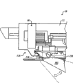
图6是按照本实用新型的闩锁组件的局部透视图,该闩锁组件位于竖锯壳体的前连接部分中,能够被按压或相反被缩回以释放龙骨组件的前连接部分,从而龙骨组件能够与壳体分开。6 is a partial perspective view of a latch assembly in accordance with the present invention located in the front connecting portion of the jigsaw housing and capable of being pressed or otherwise retracted to release the front connecting portion of the keel assembly so that the keel The assembly can be separated from the housing.
图7是按照本实用新型的竖锯的局部前视图,其中竖锯包括布置成相对于鞋状部件成不同角度用以形成各种切割角度的龙骨组件。7 is a partial front view of a jigsaw including keel members arranged at different angles relative to the shoe member to form various cutting angles in accordance with the present invention.
图8是按照本实用新型另一方面的刀片引导机构的简化局部剖面侧视图,其示出两个引导部件的其中之一从上部支承组件延伸出去,终止在几乎接触到切割刀片侧面的位置处。Figure 8 is a simplified side view, partially in section, of a blade guide mechanism according to another aspect of the present invention showing one of the two guide members extending from the upper support assembly terminating at a position nearly touching the side of the cutting blade .
图9是按照本实用新型的切割刀片的简化的局部剖面顶视图,其中切割刀片的位置对应于图8所示引导部件的硬化端部。FIG. 9 is a simplified partial section top view of a cutting blade in accordance with the present invention in a position corresponding to the hardened end of the guide member shown in FIG. 8 .
具体实施方式 Detailed ways
接下来的描述从本质上讲仅仅是示例性的,并不意在对本实用新型及其应用或使用构成限定。应当理解全部的附图中相同的附图标记表示相同或相应的部件和特征。The ensuing description is merely exemplary in nature and is not intended to limit the invention, its application or uses. It should be understood that like reference numerals indicate like or corresponding parts and features throughout the drawings.
此外,使用特定的术语也仅是参考的目的,不对本实用新型构成限定。例如,术语“上部”、“下部”、“在......上方”和“在......下面”可以表示附图中的参考方向。术语“前”、“后”、“后面”和“侧面”描述了在一致但任意的参照系中部件、功能(function)、系统等部分的方位,其中在讨论中通过参照描述部件、功能、系统等的文本和相应的附图能够使得其更加清晰。这些术语包括上面特别提到的词汇、它们的衍生词和类似含义的词语。类似的,除非在上下文中明确指示,术语“第一”、“第二”和其它这种表示结构、系统和/或方法的数值术语并不包含顺序或次序。In addition, the use of specific terms is for the purpose of reference only, and does not limit the present invention. For example, the terms "upper," "lower," "above," and "below" may denote directions of reference in the drawings. The terms "front", "rear", "rear" and "side" describe the orientation of parts, functions, systems, etc., in a consistent but arbitrary frame of reference wherein in the discussion the parts, functions, systems, etc. are described by reference The text of the system etc. and the corresponding figures can make this clearer. These terms include the words specifically mentioned above, their derivatives and words of similar import. Similarly, the terms "first", "second" and other such numerical terms referring to structures, systems and/or methods do not imply a sequence or order unless clearly indicated by the context.
参照图1,竖锯10一般包括由两个半壳14,16构成的壳体12。壳体12可以包含电机18。当由扳机组件20启动时,电机18能够向位于往复轴端部上的切割刀片保持架22提供往复和/或摇摆运动,以驱使切割刀片24成一个或多个切割角26(图7)。壳体12一侧上的控制部件28能够控制位于往复轴上的切割刀片保持架22的往复运动的速率和/或摇摆运动的幅度,从而控制切割刀片24。Referring to FIG. 1 , the
鞋状部件30能够连接到壳体12的底部32以使得允许鞋状部件30相对于壳体12枢转。当鞋状部件30相对于壳体12枢转时,切割刀片保持架22、切割刀片24等能够相对于鞋状部件30被定位成不同的角度(即一个或多个切割角26(图7))。鞋状部件30的底面34可以邻接工件36,所述工件36可以是木材、塑料、金属、其它适宜的材料和上述材料的一种或多种组合,并且可以是管材、板材、坯料、其它适宜的形式和/或材料以及上述形式的一种或多种组合。鞋状部件30能够相对于壳体12枢转以调节竖锯10的切割角26(图7),例如调节成45度切割角。The
当鞋状部件30相对于壳体12移动时,一转角指示轮38能够可旋转地连接鞋状部件30,并且能够显示出竖锯10的切割角26。此外,如图1所示,锁定机构40可以包括能够在打开(unlock)状态和锁定状态之间调节的倾斜杆(bevel lever)42。在打开状态下,锁定机构40能够允许鞋状部件30相对于壳体12枢转。在锁定状态下,如图1所示,锁定机构40能够防止鞋状部件30相对于壳体12枢转。当锁定机构40处于打开状态时,能够由转角指示轮38显示出鞋状部件30相对于壳体12枢转过的切割角26(图7)。A rotation
在鞋状部件30的后部46形成一除尘口44,从而能够利用各种适宜的连接将真空源48连接到除尘口44。能够从切割区域52抽吸出除尘气流50。除尘气流50能够从切割区域52移动通过形成在鞋状部件30中的气流通路,并且被引导出除尘口44。A dust extraction port 44 is formed in the rear portion 46 of the
竖锯10包括激光模块80。激光模块80能够发射出激光82,并且能够产生激光图案84。激光图案84例如能够在远离切割刀片24前侧86的地方形成一连串的虚线和/或点,并且能够照亮切割刀片24通过工件36的路径。The
竖锯10还包括龙骨组件100,当在工件36中直线切割时,该龙骨组件100能够提供额外的直线精度(例如能够有助于避免竖锯切割路径偏移)。当鞋状部件30相对于壳体12移动了某一角度时(即一个或多个切割角26(图7))时,龙骨组件100能够连同壳体12一起枢转。在这点上,鞋状部件30能够相对于壳体12枢转,但龙骨组件100能够和壳体12大体保持成一直线,从而形成通过工件36的直斜切(straight bevel cut),即切割角不垂直于工件36,但通过工件36的切割路径是直的。The
龙骨组件100能够连接到壳体12的底部32。鞋状部件30从壳体12延伸到鞋状部件30之外并且从竖锯10的底部32远端地向外(即向下)。龙骨组件100包括能够和下部引导组件104附连的龙骨刀片部件102。下部引导组件104能够与从壳体12延伸的上部引导组件106以各种预定距离间隔开。通过相对于上部引导组件106调节下部引导组件104,能够调整组件104,106之间的距离以容纳具有不同厚度的工件。The
参照图2和图3,龙骨组件100还可以包括可以带有凸缘110的前连接部108,其中在凸缘110上形成有孔112。龙骨组件100还包括能够限定出唇缘116的后连接部114。壳体12的后连接部118能够接纳后连接部114的唇缘116。在这点上,能够通过壳体12的后连接部118来接收龙骨组件100的后连接部114,从而唇缘116能够围绕壳体12的后连接部118枢转。Referring to FIGS. 2 and 3 , the
如图3所示,龙骨组件100能够向上摆动,以便将龙骨组件100的前连接部108定位成与壳体12的前连接部120接合。当与壳体12分开时(如虚线所示),龙骨组件100还可以向下摆动。当龙骨组件100连接到壳体12时,形成在凸缘110中的孔112能够接收壳体12的前连接部120中的闩锁组件122。As shown in FIG. 3 , the
参照图6,闩锁组件122包括能够被推动、缩回等的促动部件124。在一例子中,将促动部件124推入到闩锁部件122中能够使杆件126移动,从而使杆件126从龙骨组件100的前连接部108的凸缘110的孔112中移出。通过上述例子,能够利用使用者的一个或多个手指、拇指等推动促动部件。参照图3,当前连接部108不再由闩锁组件122夹持时,龙骨组件100能够围绕唇缘116向下摆动,这里所述唇缘116被保持在后连接部118中。同样,通过手动操作能够使龙骨组件100从壳体12上分开,因此不再需要额外的工具。Referring to FIG. 6 , the
在另一例子中,按压促动部件124能够释放(release)杆件126上的偏置(bias),从而当拉动龙骨组件100使之远离壳体12时,杆件126能够移动(例如缩回)。尽管是能够使杆件126移动的特定机构,但是当促动部件124位于伸展位置时(例如没有被使用者按压),能够通过形成在龙骨组件100前连接部108中的孔112夹持杆件126,以便将龙骨组件100固定到壳体12上。In another example, depressing the actuating
参照图7,龙骨组件100可以固定在壳体12上,并且龙骨组件100和壳体12能够保持成一直线,同时竖锯10相对于鞋状部件30移动,以形成各种切割角26。附图中示出了竖锯10的切割刀片24(图1)的一个或多个切割角26,其中一切割角26(图中实线所示)定位在零度切割角,即垂直于鞋状部件30的切割角。Referring to FIG. 7 , the
进一步,切割角130(虚线所示)被设置成大约为+15度,而切割角132(虚线所示)被设置成大约为-30度。切割角134(虚线所示)被设置成大约为+45度。根据如上所述可以理解能够实现包含上述角度的各种切割角,而且并不限于图7所示的那些切割角度。在这一方面,无论是以何种角度实现的,龙骨组件100都能够从壳体12上拆卸下来。Further, cut angle 130 (shown in dashed lines) is set to be approximately +15 degrees, and cut angle 132 (shown in dashed lines) is set to be approximately -30 degrees. Cutting angle 134 (shown in phantom) is set at approximately +45 degrees. It can be understood from the above that various cutting angles including the angles described above can be realized, and are not limited to those shown in FIG. 7 . In this regard, the
参照图2,3和5,龙骨刀片组件102可以限定出一通道150,下部支承组件104能够在该通道中移动以调节下部支承组件104和上部支承组件106之间的距离。下部支承组件104可以包括调节机构152。调节机构152可以带有能够克服弹簧156偏压(bias)缩回的调节部件154。通过移动调节部件154,带有凸轮表面160的插塞部件158能够移动,与形成在龙骨刀片部件102中的通道150的边缘162不在同一直线上。当与边缘162不在同一直线上移动凸轮表面160时,下部支承组件104能够在相对于龙骨刀片部件102的不同位置164之间移动。Referring to FIGS. 2 , 3 and 5 , the
一方面,位置164可以包括如图5所示的顶部位置166和如图3以及图5中虚线所示的底部位置168。通过上述例子,下部支承组件104的不同位置164可以被配置的以容纳切割刀片24的不同长度170以用于特定的场合。相应地,下部支承组件104的不同位置164能够实现容纳不同尺寸的工件。In one aspect, the
另一方面,插塞部件158可以具有圆形凸轮表面172,该圆形凸轮表面172能够容纳在由通道150边缘162构成的其中一个凹陷174中。尽管图中示出了三个凹陷174,即第一凹陷176,第二凹陷178和第三凹陷180,但根据所公开的内容应当理解到,在龙骨刀片部件102的通道150中能够限定出不同数量的凹陷174,其数量可以与下部支承组件104的位置164相关联。On the other hand, the
通过移动凸轮表面160使其不与形成在龙骨刀片部件102中的通道150的边缘162接触,下部支承组件104能够相对于龙骨刀片部件102移动到其中一个选定的位置164上。在这个所选定的位置164上,调节部件154能够移动至延伸(extended)状态,以使得插塞部件158的凸轮表面160能够再次接触通道150的边缘162,由此将下部支承组件104保持在所选定的位置上。By moving
参照图2,下部支承组件104可以包括一对臂形部件182,这对臂形部件182能够和位于它们之间的龙骨刀片部件102紧固在一起。每个臂形部件182都可以包括一个或多个孔。例如,在每个臂形部件182上可以形成有后孔184、中间孔186和前孔188。后孔184用来接收紧固件190,该紧固件能够插入到形成在龙骨刀片部件102中的凹槽192中。当下部支承组件104相对于龙骨刀片部件102移动时,紧固件190能够在凹槽192中移动。Referring to FIG. 2 , the
在其中一个臂形部件182上,中间孔186可以是特大尺寸的孔(相对于其它孔)194,用以接收插塞部件158。相对的另一个臂形部件182的相对的中间孔186可以用来接收调节部件154的一部分。在这种布置中,调节部件154能够被插入穿过弹簧156,这里所述弹簧可以设置在其中一个臂形部件182的表面196和调节部件154的头部198之间。调节部件154可以与插塞部件158相连(例如通过机械螺纹),从而将弹簧156固定到头部198和表面196之间。前孔188可以用来接收紧固件200,该紧固件能够旋转地夹持着位于每个臂形部件182之间的滚动部件202。滚动部件202可以带有凹槽204用来接收切割刀片24的后刃206(图3)。On one of the
龙骨组件100可以进一步包括连接在龙骨刀片部件102上的龙骨块(keel block)230。龙骨刀片部件102可以限定第一凸起232和第二凸起234。第一凸起232可以包括一孔236,同时第二凸起234可以包括第二孔238。包含凸起232,234的龙骨刀片部件102的一部分可以接收在形成在龙骨块230中的凹槽240内(图中虚线所示)。紧固件242可以通过形成在龙骨块230中的孔和形成在龙骨刀片部件102中的孔236,238,使龙骨刀片部件102靠近龙骨块230。结果,如在图3中部分地示出,龙骨块230可以与壳体12相连。The
参照图8和图9,按照本实用新型的另一方面,上部支承部件300可以包括滚动部件302或能够与竖锯10的切割刀片24的后刃206(即非切割部分)邻接的其它适宜的部件。两个引导部件306可以从上部支承部件300伸出,并可以终止在几乎接触到切割刀片24侧面308的位置处。在每一引导部件306的末端310,可以设置有硬化部分312,以使得当切割刀片24接触引导部件306时,切割刀片24能够接触到硬化部分312。每个硬化部分312都比制成引导部件306的材料更硬。Referring to FIGS. 8 and 9 , according to another aspect of the present invention, the
当竖锯10沿直线切割并且通常不对切割刀片24造成扭曲时,切割刀片24的侧面38将不会接触到引导部件306的硬化部分312。在其它情况下,切割刀片24可以切入工件,并且会对切割刀片24造成扭曲,从而刀片的扭曲可以迫使切割刀片24的侧面308接触到引导部件306的硬化部分312。在一例子中,切割刀片24的扭曲会是由于切割刀片24尤其是在湿木材(生材)中顺着木材的纹理。The
可以表明,在切割刀片24的侧面308附近保持引导部件306特别是硬化部分312能够减少切割刀片24的扭曲,并且能够减少从直的切割线偏离。同样,引导部件306的端部310能够保持足够靠近切割刀片24以减少切割刀片24的扭曲,这是由于硬化部分312能够至少部分阻碍扭曲的切割刀片24的侧面308,因此能够防止切割刀片24扭曲(或扭曲到一定程度)。It can be shown that maintaining the
根据上述公开内容可以认识到,在使用竖锯刻花时,是由于切割刀片24和工件36之间的作用力导致产生扭曲,并不是因为随意实现的滚动功能造成的,虽然这里所述滚动功能会对切割刀片24造成扭曲,使得切割刀片相对容易转动。According to the above disclosure, it can be recognized that when using a jigsaw to engrave, the distortion is caused by the force between the cutting
尽管在说明书和附图中已经描述了特定方面,但本领域技术人员应当理解的是在不脱离由权利要求限定的本实用新型的范围内,可以进行各种改变和元件、部件的等效替换。此外,能够清楚地预料到本实用新型不同方面之间特征、元件、部件和/或功能的混合和匹配,从而本领域技术人员根据本实用新型的教导可知本实用新型其中一方面的特征、元件、部件和/或功能能够被并入到可以理解的另一方面,除非上文中另有说明。此外,在不脱离本实用新型的实质范围内,可以进行多种改进来适应特定的情形、结构或材料。因此,本实用新型并不局限于附图和说明书中描述的特定方面,这只是实现本实用新型教导的最佳方式,本实用新型的范围包括在前面的描述和权利要求中的许多方面和例子。Although certain aspects have been described in the specification and drawings, it will be understood by those skilled in the art that various changes and equivalent substitutions of elements and components may be made without departing from the scope of the present invention defined by the claims. . In addition, mixing and matching of features, elements, parts and/or functions between different aspects of the present invention can be clearly expected, so that those skilled in the art can know the features and elements of one aspect of the present invention according to the teaching of the present invention. , components and/or functions can be incorporated into another understandable aspect unless otherwise stated above. In addition, many modifications may be made to adapt a particular situation, construction or material without departing from the essential scope of the invention. Therefore, the utility model is not limited to the specific aspects described in the accompanying drawings and the description, which is only the best way to realize the teaching of the utility model, and the scope of the utility model includes many aspects and examples in the foregoing description and claims .
Claims (15)
Applications Claiming Priority (2)
| Application Number | Priority Date | Filing Date | Title |
|---|---|---|---|
| US11/859,172 | 2007-09-21 | ||
| US11/859,172 US8033026B2 (en) | 2007-09-21 | 2007-09-21 | Adjustable and removable keel assembly and blade guide for a jigsaw |
Publications (1)
| Publication Number | Publication Date |
|---|---|
| CN201329450Y true CN201329450Y (en) | 2009-10-21 |
Family
ID=40120429
Family Applications (1)
| Application Number | Title | Priority Date | Filing Date |
|---|---|---|---|
| CNU2008201798771U Expired - Fee Related CN201329450Y (en) | 2007-09-21 | 2008-09-22 | Jig saw |
Country Status (4)
| Country | Link |
|---|---|
| US (2) | US8033026B2 (en) |
| EP (1) | EP2039455B1 (en) |
| CN (1) | CN201329450Y (en) |
| AU (1) | AU2008221557A1 (en) |
Families Citing this family (21)
| Publication number | Priority date | Publication date | Assignee | Title |
|---|---|---|---|---|
| US9364907B2 (en) * | 2007-12-11 | 2016-06-14 | Black & Decker Inc. | Jigsaw blade |
| DE102008001479A1 (en) * | 2008-04-30 | 2009-11-05 | Robert Bosch Gmbh | Power tool |
| DE102008055061A1 (en) * | 2008-12-22 | 2010-06-24 | Robert Bosch Gmbh | Guiding system for machine tools |
| US20110058356A1 (en) | 2009-02-25 | 2011-03-10 | Black & Decker Inc. | Power tool with light emitting assembly |
| US8328381B2 (en) | 2009-02-25 | 2012-12-11 | Black & Decker Inc. | Light for a power tool and method of illuminating a workpiece |
| US8317350B2 (en) | 2009-02-25 | 2012-11-27 | Black & Decker Inc. | Power tool with a light for illuminating a workpiece |
| US12059780B2 (en) | 2010-09-30 | 2024-08-13 | Black & Decker Inc. | Lighted power tool |
| US9028088B2 (en) | 2010-09-30 | 2015-05-12 | Black & Decker Inc. | Lighted power tool |
| US9328915B2 (en) | 2010-09-30 | 2016-05-03 | Black & Decker Inc. | Lighted power tool |
| US8857066B2 (en) * | 2011-08-22 | 2014-10-14 | Robert Bosch Gmbh | Power saw including an impact mechanism |
| US8578615B2 (en) * | 2011-09-12 | 2013-11-12 | Black & Decker Inc. | Jigsaw with deployable keel and tiltable shoe |
| USD675077S1 (en) * | 2011-09-23 | 2013-01-29 | Black & Decker Inc. | Jigsaw |
| US9242355B2 (en) | 2012-04-17 | 2016-01-26 | Black & Decker Inc. | Illuminated power tool |
| JP5995785B2 (en) * | 2013-05-31 | 2016-09-21 | 株式会社マキタ | Brush cutter |
| US20160243633A1 (en) * | 2013-10-01 | 2016-08-25 | Hitachi Koki Co., Ltd. | Cutting tool |
| US9559628B2 (en) | 2013-10-25 | 2017-01-31 | Black & Decker Inc. | Handheld power tool with compact AC switch |
| CN103722591A (en) * | 2014-01-03 | 2014-04-16 | 华国洋 | Linear guiding device for jig saw |
| DE102014226025A1 (en) * | 2014-12-16 | 2016-06-16 | Robert Bosch Gmbh | Optical display device unit for use in an external application unit |
| US10207348B2 (en) * | 2016-06-08 | 2019-02-19 | Jpw Industries Inc. | Dual position blade guide for vertical or horizontal position of band saw |
| US10136655B2 (en) * | 2016-10-19 | 2018-11-27 | William M Haack | Saw blade illuminating safety device |
| US10544597B2 (en) * | 2017-12-04 | 2020-01-28 | Rhino Tools and Equipment Inc. | Tool attachment for raking mortar joints |
Family Cites Families (218)
| Publication number | Priority date | Publication date | Assignee | Title |
|---|---|---|---|---|
| US1102018A (en) * | 1912-06-06 | 1914-06-30 | Kerner Mfg Company | Power-driven handsaw. |
| GB221671A (en) | 1923-10-22 | 1924-09-18 | George Scattergood | Improvements in or relating to guards for circular saws |
| DE716266C (en) | 1937-06-01 | 1942-01-15 | Hans Ehlermann Dipl Ing | Device for dissipating the heat from the rotor core of electric hand tools |
| US2377673A (en) * | 1944-08-21 | 1945-06-05 | Clarence F Chaddock | Blade guide for motor-driven circular handsaws |
| US2623557A (en) | 1951-06-05 | 1952-12-30 | John T Kendall | Portable power-driven recessing apparatus |
| DE1628899U (en) | 1951-07-17 | 1951-10-04 | Richard Muetschele | FILLING DEVICE FOR LIQUID GASES. |
| US2749951A (en) * | 1952-04-17 | 1956-06-12 | Tetzner Gustav | Band saw blade guide |
| US2775272A (en) | 1953-11-27 | 1956-12-25 | Walter A Papworth | Portable power driven reciprocable cutting tool |
| US2819742A (en) * | 1955-07-05 | 1958-01-14 | Oster John Mfg Co | Kerf guide and splitter |
| DE1760076U (en) | 1957-11-26 | 1958-01-16 | Metabowerk Closs Rauch & Schni | PROTECTIVELY INSULATED ELECTRICAL TOOLS, IN PARTICULAR JIGSAW. |
| US2934106A (en) * | 1958-01-09 | 1960-04-26 | Continental Machines | Saw band guide |
| DE1795934U (en) | 1958-02-11 | 1959-09-17 | Scintilla Ag | ADDITIONAL DEVICE FOR A MOTOR-DRIVEN HAND SAW. |
| US2916062A (en) * | 1958-09-18 | 1959-12-08 | Dormeyer Corp | Splitter for portable electric saw |
| US3093773A (en) * | 1959-03-23 | 1963-06-11 | Fed Pacific Electric Co | Panelboard with circuit protective devices |
| US3087519A (en) * | 1960-11-25 | 1963-04-30 | Black & Decker Mfg Co | Pivoting shoe for portable electric jig saw |
| US3146809A (en) | 1961-04-06 | 1964-09-01 | Skil Corp | Adjustable guide plate for jig saws |
| US3131736A (en) * | 1961-04-10 | 1964-05-05 | Milwaukee Electric Tool Corp | Portable motor driven jig saw |
| US3109465A (en) | 1961-05-19 | 1963-11-05 | Sure Hit Products Inc | Saw guide assemblies |
| US3116768A (en) * | 1962-05-07 | 1964-01-07 | Lasar William | Band saw guide |
| DE1279923B (en) * | 1965-01-21 | 1968-10-10 | Scintilla Ag | Device for generating an additional feed movement for the saw blade of a jigsaw machine |
| US3353573A (en) | 1965-05-19 | 1967-11-21 | Mc Graw Edison Co | Portable power tool |
| DE1278728B (en) * | 1966-03-25 | 1968-09-26 | Ackermann U Schmitt K G | Guide device on a motor-driven jigsaw |
| US3388728A (en) * | 1966-04-15 | 1968-06-18 | Martin Marietta Corp | Portable power tools |
| US3457796A (en) * | 1966-06-23 | 1969-07-29 | Rockwell Mfg Co | Tool |
| US3461732A (en) | 1966-12-19 | 1969-08-19 | Rockwell Mfg Co | Portable power driven reciprocating saw |
| US3478786A (en) | 1967-02-03 | 1969-11-18 | Otto Hendrickson | Adjustably controlled saber saw |
| US3542097A (en) | 1968-05-02 | 1970-11-24 | Singer Co | Chuck assembly for sabre saws |
| US3834019A (en) | 1972-11-22 | 1974-09-10 | Maremont Corp | Apparatus for cutting exhaust system tubes |
| US3805383A (en) * | 1972-11-22 | 1974-04-23 | Maremont Corp | Exhaust system tube cutting apparatus with improved cutting efficiency |
| SE395606B (en) | 1973-12-04 | 1977-08-22 | Persson Curt | SAWING DEVICE FOR CUTTING UP A PLASTER or other similarly shaped body |
| DE2435845C2 (en) | 1974-07-25 | 1984-09-20 | Metabowerke KG Closs, Rauch & Schnizler, 7440 Nürtingen | Motor-driven jigsaw with tiltable table |
| US3938251A (en) * | 1975-03-10 | 1976-02-17 | The Raymond Lee Organization, Inc. | Saber or jig saw with demountable foot plate and shield |
| US3969796A (en) * | 1975-09-17 | 1976-07-20 | General Electric Company | Releasable fastening arrangement for a radio housing and a battery housing |
| DE2546527C2 (en) * | 1975-10-17 | 1993-05-27 | Robert Bosch Gmbh, 7000 Stuttgart | Jigsaw |
| DE2650470C2 (en) | 1976-11-04 | 1984-03-22 | Eugen Lutz GmbH u. Co Maschinenfabrik, 7130 Mühlacker | Jigsaw |
| DE2655583C2 (en) * | 1976-12-08 | 1982-07-01 | Black & Decker, Inc., 19711 Newark, Del. | Jigsaw |
| US4191917A (en) * | 1977-08-25 | 1980-03-04 | Disston, Inc. | Battery pack rechargeable in recessed or flush-type receptacles |
| US4262421A (en) * | 1978-08-11 | 1981-04-21 | Eugen Lutz Gmbh & Co. Maschinenfabrik | Keyhole saw |
| US4213242A (en) * | 1979-01-22 | 1980-07-22 | Partington Everett J | Attachment for saber saw |
| US4250624A (en) * | 1979-01-22 | 1981-02-17 | Partington Everett J | Miter table for use with a saber saw |
| US4257297A (en) * | 1979-01-31 | 1981-03-24 | Peter Nidbella | Circular saw with visual cut line indicator |
| US4272889A (en) * | 1979-02-26 | 1981-06-16 | Omark Industries, Inc. | Portable saw |
| US4255006A (en) * | 1979-06-11 | 1981-03-10 | Conair Corporation | Strain-relief member for reducing torsional strains in line cord |
| US4255858A (en) * | 1979-06-18 | 1981-03-17 | Getts Sidney Arthur | Jig saw with orbitally movable blade |
| US4238884A (en) | 1979-06-19 | 1980-12-16 | Black & Decker Inc. | Orbital jig saw |
| US4240204A (en) | 1979-06-19 | 1980-12-23 | Black & Decker Inc. | Jig saw |
| JPS6119487Y2 (en) * | 1979-06-19 | 1986-06-12 | ||
| US4283855A (en) | 1980-04-07 | 1981-08-18 | The Singer Company | Sabre saw with rotatable saw bar |
| DE8012652U1 (en) | 1980-05-09 | 1982-01-28 | Scintilla Ag, Solothurn | Hand machine tool, in particular a jigsaw |
| DE3021801C2 (en) | 1980-06-11 | 1985-03-21 | Licentia Patent-Verwaltungs-Gmbh, 6000 Frankfurt | Jigsaw with support table that can be attached to the saw housing |
| DE8033115U1 (en) | 1980-12-12 | 1981-05-21 | Zimlich, Ernst, 8000 München | SAW |
| US4351112A (en) | 1981-02-20 | 1982-09-28 | The Singer Company | Sabre saw bar and blade holder |
| DE3118758C2 (en) | 1981-05-12 | 1986-04-30 | Licentia Patent-Verwaltungs-Gmbh, 6000 Frankfurt | Device for generating and adjusting an additional feed movement transversely to the longitudinal direction of the saw blade of a jigsaw machine |
| DE3222426C1 (en) | 1982-06-15 | 1983-12-22 | Metabowerke GmbH & Co, 7440 Nürtingen | Electric hand tools, in particular jigsaws for do-it-yourselfers |
| JPS59163608A (en) | 1983-03-08 | 1984-09-14 | Hitachi Koki Co Ltd | Jigsaw |
| DE3329971A1 (en) * | 1983-08-19 | 1985-03-07 | Robert Bosch Gmbh, 7000 Stuttgart | CONTROL AND OPERATING DEVICE FOR AN ELECTRIC HAND TOOL |
| DE3403762A1 (en) | 1984-02-03 | 1985-08-14 | Festo KG, 7300 Esslingen | Device for releasably fastening a splitting wedge to a saw |
| DE3408847A1 (en) | 1984-03-10 | 1985-11-14 | Black & Decker Inc., Newark, Del. | Compass saw |
| US4545123A (en) | 1984-04-09 | 1985-10-08 | Skil Corporation | Combination jig saw adjusting mechanism |
| GB2158393B (en) | 1984-05-11 | 1987-05-20 | Black & Decker Inc | Scroller jig saw |
| DE3420442A1 (en) * | 1984-06-01 | 1985-12-05 | Festo KG, 7300 Esslingen | JIGSAW |
| US4614037A (en) | 1984-08-10 | 1986-09-30 | Black & Decker, Inc. | Accessory storage device for electric jigsaw |
| US4675999A (en) * | 1984-11-16 | 1987-06-30 | Hitachi Koki Company, Ltd. | Portable power tool equipped with dust collector |
| DE3543764A1 (en) | 1984-12-13 | 1986-06-19 | Vsesojuznyj naučno-issledovatel'skij i proektno-konstruktorskij institut mechanizirovannogo i ručnogo stroitel'no-montažnogo instrumenta, vibratorov i stroitel'no-otdeločnych mašin VNNISMI, Chimki, Moskovskaja oblast' | Jigsaw |
| DE3446278A1 (en) | 1984-12-19 | 1986-06-26 | Metabowerke GmbH & Co, 7440 Nürtingen | Jigsaw |
| DE3546700C2 (en) | 1985-03-16 | 1990-10-25 | Festo Kg, 7300 Esslingen, De | Portable power fret saw |
| DE3509515C3 (en) | 1985-03-16 | 1994-04-14 | Festo Kg | Jigsaw |
| DE8507818U1 (en) | 1985-03-16 | 1987-02-19 | Festo KG, 7300 Esslingen | Jigsaw |
| US4628605A (en) | 1985-06-10 | 1986-12-16 | Porter-Cable Corporation | Orbital bayonet saw |
| US4730397A (en) * | 1985-08-09 | 1988-03-15 | Black & Decker, Inc. | Jig saw with two-piece shoe |
| DE3608301A1 (en) | 1986-03-13 | 1987-09-17 | Metabowerke Kg | JIGSAW WITH A HAND-DRIVABLE MACHINE HOUSING |
| DE3613279A1 (en) * | 1986-04-19 | 1987-10-22 | Festo Kg | JIGSAW |
| DE3712236A1 (en) * | 1987-04-10 | 1988-10-27 | Bosch Gmbh Robert | JIGSAW |
| US4833782A (en) * | 1987-06-01 | 1989-05-30 | Robert E. Strauss | Saber saw tracing light |
| SU1558674A1 (en) | 1987-06-23 | 1990-04-23 | Московское Научно-Производственное Объединение По Механизированному Строительному Инструменту И Отделочным Машинам | Mechanical scroll saw |
| DE3820752A1 (en) | 1988-06-18 | 1989-12-21 | Reich Maschf Gmbh Karl | JIGSAW WITH SUCTION |
| US4962681A (en) | 1988-11-09 | 1990-10-16 | Yang Tai Her | Modular manual electric appliance |
| US5208525A (en) * | 1988-12-10 | 1993-05-04 | Gardena Kress + Kastner Gmbh | Electric power supply assembly for a cordless electric appliance |
| US4969830A (en) | 1989-06-12 | 1990-11-13 | Grid Systems Corporation | Connection between portable computer components |
| DE3921891A1 (en) | 1989-07-04 | 1991-01-17 | Black & Decker Inc | Jigsaw with pendulum mechanism - has mechanism driven by main motor to move saw blade to=and=fro as well as well as up=and=down |
| US4932294A (en) * | 1989-07-18 | 1990-06-12 | Chang Jung C | DIY electric hand tool having a chamber for accommodating tool heads not in use |
| US4973205A (en) | 1989-12-18 | 1990-11-27 | Silas Spaulding | Hand drill apparatus |
| GB8928879D0 (en) | 1989-12-21 | 1990-02-28 | Amp Gmbh | Connector keying system |
| US5010652A (en) * | 1990-03-19 | 1991-04-30 | Miletich David J | Optically guided power sabre saw |
| DE4009405A1 (en) * | 1990-03-23 | 1991-09-26 | Nienstedt Heinz Maschf | SAW BAND GUIDE |
| US5038481A (en) | 1990-05-04 | 1991-08-13 | Lonnie Smith | Saber saw tracking light |
| DE4027135C2 (en) | 1990-08-28 | 1995-09-07 | Gerhard Netz | Jigsaw with speed control |
| GB9101460D0 (en) * | 1991-01-23 | 1991-03-06 | Black & Decker Inc | Pendulum jigsaws |
| DE4108710A1 (en) | 1991-03-16 | 1992-09-17 | Bosch Gmbh Robert | HAND MACHINE TOOL WITH GUIDE BEAM |
| WO1992022146A1 (en) * | 1991-06-03 | 1992-12-10 | Motorola, Inc. | Portable radio battery latch |
| DE4121989A1 (en) | 1991-07-03 | 1993-01-07 | Festo Kg | JIGSAW |
| US5996460A (en) | 1992-03-13 | 1999-12-07 | Waite; Lance H. | Cut line indicator for power cutting material |
| DE4244079A1 (en) * | 1992-12-24 | 1994-06-30 | Scintilla Ag | Hand tool |
| US5279037A (en) * | 1993-01-04 | 1994-01-18 | Locksley S. Hall | Guide for a portable saw |
| DE9307337U1 (en) | 1993-05-14 | 1993-07-15 | Kress-Elektrik GmbH & Co. Elektromotorenfabrik, 7457 Bisingen | Saw table for a jigsaw |
| DE4316155C2 (en) | 1993-05-14 | 1996-04-04 | Kress Elektrik Gmbh & Co | Saw table for a jigsaw |
| DE4320233C1 (en) | 1993-06-18 | 1994-06-16 | Atlas Copco Elektrowerkzeuge | Fret saw machine with adjustable sawblade support device - involves sawblades of varying thickness laterally to be fed to vicinity of workpiece by at least two linear guide slots on support device |
| US5445479A (en) | 1994-08-17 | 1995-08-29 | Hillinger; George | Ergonomically designed, electrically energized hand drill having a housing, longitudinally aligned with a hand, wrist and forearm support |
| JPH08155730A (en) * | 1994-12-12 | 1996-06-18 | Makita Corp | Base mounting structure in cutting tool |
| DE59408620D1 (en) * | 1994-12-16 | 1999-09-16 | Ceka Elektrowerkzeuge Ag & Co | Pendulum stroke drive for jigsaws |
| DE59408621D1 (en) * | 1994-12-16 | 1999-09-16 | Ceka Elektrowerkzeuge Ag & Co | Device for pivotably attaching a saw table to a jigsaw |
| JP3251456B2 (en) | 1995-03-10 | 2002-01-28 | 株式会社マキタ | Jigsaw dust suction device |
| DE19513076A1 (en) | 1995-04-07 | 1996-10-10 | Scintilla Ag | Jigsaw |
| DE19513078B4 (en) | 1995-04-07 | 2006-07-06 | Scintilla Ag | jigsaw |
| US6017242A (en) * | 1995-06-05 | 2000-01-25 | Tensolite Company | Right-angled coaxial cable connector |
| US5549145A (en) | 1995-06-16 | 1996-08-27 | Bearden; Herman G. | Balancing skid for tree harvesting machine |
| JP2842308B2 (en) * | 1995-06-30 | 1999-01-06 | 日本電気株式会社 | Battery case mounting structure for electronic equipment |
| DE19604938B4 (en) | 1995-08-24 | 2007-05-03 | Narex Česká Lípa a.s. | Device for adjusting the size of the advancing movement of the saw blade of a jigsaw machine |
| DE19609388A1 (en) | 1996-03-01 | 1997-09-04 | Black & Decker Inc | Motor-driven compass saw |
| DE29604333U1 (en) | 1996-03-08 | 1997-07-17 | Scintilla Ag, Solothurn | Hand-held, electric jigsaw |
| US5675899A (en) | 1996-05-28 | 1997-10-14 | Webb; James | Rotary saw with laser beam alignment |
| EP0826453A1 (en) | 1996-08-27 | 1998-03-04 | Kambo AG | Equipment for a jigsaw |
| US5813805A (en) | 1996-08-29 | 1998-09-29 | Kopras; Robert K. | Spiral cutting tool with detachable handle |
| US5784800A (en) * | 1996-11-08 | 1998-07-28 | Conair Corporation | Cord reel dryer |
| US5727322A (en) * | 1996-12-31 | 1998-03-17 | Black & Decker Inc. | Adjustable shoe for a jig saw |
| ATE356683T1 (en) | 1997-01-31 | 2007-04-15 | Black & Decker Inc | MOTORIZED SAW WITH RECIVERTING BLADE AND WORKPIECE HOLDING DEVICE |
| AU7688498A (en) * | 1997-05-19 | 1998-12-11 | Stephen S. Daniell | Powered cutting saw system and method for joining materials |
| WO1999002310A2 (en) | 1997-07-10 | 1999-01-21 | Avos Developments Limited | Illumination for power tools |
| US5902080A (en) * | 1997-07-11 | 1999-05-11 | Roto Zip Tool Corporation | Spiral cutting tool with detachable battery pack |
| GB2330328A (en) | 1997-10-15 | 1999-04-21 | John Duffy | Jigsaw blade guide and support assembly |
| AUPP166398A0 (en) | 1998-02-05 | 1998-02-26 | Tool Concepts Pty Ltd | Cutting tool |
| DE19819530A1 (en) | 1998-04-30 | 1999-11-04 | Scintilla Ag | Hand tool machine with quick action chuck for clamping tool |
| DE19821185A1 (en) | 1998-05-12 | 1999-11-18 | Scintilla Ag | Hand-held machine tool esp. jig saw |
| US6157545A (en) | 1998-05-14 | 2000-12-05 | Motorola, Inc. | Battery connection apparatus with end projections |
| US6189217B1 (en) * | 1998-06-17 | 2001-02-20 | Black & Decker Inc. | Power saw having blade storage chamber |
| US6357124B1 (en) * | 1998-07-10 | 2002-03-19 | Porter-Cable Corporation | Clamp system for a jigsaw tilt base |
| US6178646B1 (en) * | 1998-07-10 | 2001-01-30 | Porter-Cable Corporation | Blade clamping system for a jigsaw |
| EP0970771A3 (en) | 1998-07-10 | 2000-05-03 | Porter-Cable Corporation | Jigsaw blade clamping system with cam-operated clamping member |
| US6230411B1 (en) * | 1998-07-10 | 2001-05-15 | Porter-Cable Corporation | Blade guide system for a jigsaw |
| JP2000343309A (en) | 1999-06-08 | 2000-12-12 | Amiya Sadayuki | Machining position displaying device |
| DE19926387A1 (en) | 1999-06-10 | 2000-12-14 | Atlas Copco Electric Tools | Tool support has support plate , cylindrical-sectioned plinth, tensioning bolt, lever, counter surface, and threaded screw bolt |
| DE29910173U1 (en) | 1999-06-11 | 1999-09-02 | FESTO Tooltechnic GmbH & Co., 73728 Esslingen | Jigsaw |
| US6220888B1 (en) * | 1999-06-25 | 2001-04-24 | Hubbell Incorporated | Quick disconnect cable connector device with integral body and strain relief structure |
| CA2285638A1 (en) * | 1999-07-26 | 2001-01-26 | Louis C. Brickner, Jr. | Improved dust collection system |
| USD440474S1 (en) * | 1999-11-22 | 2001-04-17 | Choon Nang Electrical Appliance Mfy., Ltd. | Electric jigsaw |
| US6305089B1 (en) | 1999-12-20 | 2001-10-23 | Isx Company | Cutting guide |
| US6334743B1 (en) * | 2000-02-09 | 2002-01-01 | Liao Yung-Chuan | High-speed rotary machine |
| US6443675B1 (en) | 2000-02-17 | 2002-09-03 | Roto Zip Tool Corporation | Hand-held power tool |
| GB0005821D0 (en) * | 2000-03-10 | 2000-05-03 | Black & Decker Inc | Coupling method |
| US6484409B2 (en) * | 2000-04-21 | 2002-11-26 | Black & Decker Inc. | Pruner attachment apparatus for a power tool |
| US6357123B1 (en) * | 2000-09-06 | 2002-03-19 | John Manuel | Jigsaw apparatus |
| DE10045890A1 (en) | 2000-09-16 | 2002-04-04 | Bosch Gmbh Robert | Saw with a tool guide mechanism |
| JP3710697B2 (en) | 2000-09-19 | 2005-10-26 | 株式会社マキタ | Reciprocating cutting tool |
| NL1016426C2 (en) | 2000-10-18 | 2002-04-22 | Skil Europ Bv | Jigsaw provided with a rigid bearing element. |
| NL1017155C2 (en) * | 2001-01-19 | 2002-07-22 | Skil Europ Bv | Assembly of foot and jigsaw. |
| EP1393140A4 (en) * | 2001-02-22 | 2013-04-24 | Robert Bosch Co Ltd | Tools with orientation detection |
| JP2002337101A (en) | 2001-05-15 | 2002-11-27 | Makita Corp | Jigsaw |
| US6755107B2 (en) | 2001-05-18 | 2004-06-29 | One World Technologies Lmt. | Miter saw having a light beam alignment system |
| JP2002337102A (en) | 2001-05-18 | 2002-11-27 | Makita Corp | Dust collector of jig saw |
| US6553675B2 (en) * | 2001-05-23 | 2003-04-29 | S-B Power Tool Company | Quick release footplate assembly for a jigsaw |
| JP4248766B2 (en) * | 2001-05-23 | 2009-04-02 | 株式会社マキタ | Reciprocating cutting tool |
| DE50111491D1 (en) | 2001-07-26 | 2007-01-04 | Hilti Ag | Jigsaw with a lift gate with curved guide surface |
| AU148144S (en) * | 2001-09-15 | 2002-06-12 | Positec Power Tools Suzhou Co Ltd | Power tool |
| USD463963S1 (en) | 2001-12-13 | 2002-10-08 | S-B Power Tool Company | Jigsaw |
| US20030121389A1 (en) | 2002-01-02 | 2003-07-03 | Wheeler Thomas J. | Reciprocating saw |
| US20030145472A1 (en) | 2002-02-01 | 2003-08-07 | Swift Edgar Leon | Reciprocating saw with flush cutting capability |
| DE10205378A1 (en) * | 2002-02-09 | 2003-08-21 | Bosch Gmbh Robert | Portable jigsaw |
| DE10215871C1 (en) | 2002-04-11 | 2003-10-30 | Laser Optoelektronik Gmbh Z | Laser projection device for rotary saw with detection of ambient light level for controlling intensity of laser light beam used for optical marking of cutting line |
| JP4244615B2 (en) | 2002-04-22 | 2009-03-25 | 日立工機株式会社 | Electric cutting machine |
| CN2562908Y (en) | 2002-04-23 | 2003-07-30 | 南京泉峰国际贸易有限公司 | Curve saw with laser aligning device |
| CN2561565Y (en) * | 2002-05-14 | 2003-07-23 | 南京泉峰国际贸易有限公司 | Electric annular saw with laser aligning device |
| EP1515820B1 (en) | 2002-06-17 | 2008-01-02 | Robert Bosch Gmbh | Hand-operated jig-saw with saw blade guidance system |
| US20030233921A1 (en) * | 2002-06-19 | 2003-12-25 | Garcia Jaime E. | Cutter with optical alignment system |
| GB2394692B (en) | 2002-10-28 | 2005-08-17 | Black & Decker Inc | Support mechanism for reciprocating tool and tool incorporating such mechanism |
| USD476871S1 (en) | 2002-11-02 | 2003-07-08 | S-B Power Tool Corporation | Jigsaw |
| US6742421B1 (en) * | 2002-12-11 | 2004-06-01 | Jui-Tung Chen | Screwdriver |
| US7131180B2 (en) | 2003-01-08 | 2006-11-07 | Credo Technology Corporation | Attachment for power tool |
| US7065884B2 (en) * | 2003-02-28 | 2006-06-27 | Credo Technology Corporation | Power hand tool foot assembly |
| US6912788B2 (en) | 2003-03-03 | 2005-07-05 | Credo Technology Corporation | Blade storage compartment for power tool vacuum port |
| GB2399537A (en) | 2003-03-13 | 2004-09-22 | Black & Decker Inc | Method and apparatus for removing dust from a workpiece |
| GB2399314B (en) | 2003-03-13 | 2005-02-23 | Black & Decker Inc | Power tool having rotatable adjustment means for working member |
| GB2399315A (en) | 2003-03-13 | 2004-09-15 | Black & Decker Inc | Method and apparatus for removing dust from a workpiece |
| DE20305133U1 (en) * | 2003-03-31 | 2003-06-12 | Hilti Ag, Schaan | Hand tool with bit reserve |
| DE10328061A1 (en) * | 2003-06-23 | 2005-01-20 | Robert Bosch Gmbh | Motor-driven jigsaw |
| US7234243B2 (en) | 2003-06-25 | 2007-06-26 | Credo Technology Corporation | Reciprocating cutting tool with orbital action |
| AU157250S (en) * | 2003-07-28 | 2005-01-12 | Positec Power Tools Suzhou Co Ltd | Jigsaw |
| GB2415660A (en) | 2004-06-29 | 2006-01-04 | Black & Decker Inc | Shoe assembly for power tool |
| US7007481B2 (en) * | 2003-09-10 | 2006-03-07 | General Electric Company | Thick coated combustor liner |
| GB2406071A (en) | 2003-09-17 | 2005-03-23 | Black & Decker Inc | Shoe assembly for reciprocating tool |
| US7526867B2 (en) * | 2003-09-19 | 2009-05-05 | Gmca Pty Limited | Tool with clamping apparatus and an improved scrolling mechanism |
| US20070180711A1 (en) | 2003-09-19 | 2007-08-09 | Keith Park | Jigsaw actuation mechanism for imparting scrolling, orbital and reciprocating movement |
| US20050217448A1 (en) | 2003-11-14 | 2005-10-06 | Walker Thomas E | Laser illuminator for indicating a saw kerf and kerf location on a power saw |
| USD522335S1 (en) * | 2003-11-26 | 2006-06-06 | Black & Decker Inc. | Jigsaw |
| US20050195592A1 (en) | 2004-03-08 | 2005-09-08 | Hung - Chi Hsu | Handsaw having sawing guide function |
| GB0405729D0 (en) * | 2004-03-15 | 2004-04-21 | Gmca Pty Ltd | Power tool bearing arrangement |
| GB0408200D0 (en) | 2004-04-13 | 2004-05-19 | Gmca Pty Ltd | Guideline generation apparatus for power tool |
| US7296356B2 (en) | 2004-04-14 | 2007-11-20 | Eastway Fair Company Limited | Toolless adjustable base for a portable saw |
| US7174644B2 (en) | 2004-05-13 | 2007-02-13 | Cooper Brands, Inc. | Handsaw with blade storage and auxiliary blade |
| CA108960S (en) | 2004-05-13 | 2006-02-13 | Nanjing Chervon Ind Co Ltd | Reciprocating saw |
| ATE340670T1 (en) | 2004-05-18 | 2006-10-15 | Black & Decker Inc | ARRANGEMENT OF AN OUTPUT Plunger AND MOTORIZED TOOL HAVING SUCH ARRANGEMENT |
| ATE407760T1 (en) | 2004-05-18 | 2008-09-15 | Black & Decker Inc | HOLDING DEVICE FOR THE OUTPUT SHAFT OF A RACING POWER TOOL |
| ES2303027T3 (en) * | 2004-05-18 | 2008-08-01 | Black & Decker Inc. | MOTORIZED TOOL THAT INCLUDES A OPERATING MODE SELECTION MECHANISM. |
| CA2568529A1 (en) | 2004-05-28 | 2005-12-15 | Scientific Molding Corporation Ltd. | Hand-held circular saw, in particular plunge-cut saw |
| CN2747008Y (en) * | 2004-06-01 | 2005-12-21 | 南京德朔实业有限公司 | Turning saw |
| USD524622S1 (en) | 2004-07-29 | 2006-07-11 | Black & Decker Inc. | Jigsaw |
| USD519805S1 (en) * | 2004-08-26 | 2006-05-02 | Winsource Industries Limited | Electric jigsaw |
| DE102004042025A1 (en) | 2004-08-31 | 2006-03-02 | Robert Bosch Gmbh | Power tool with double switch |
| DE102004043564A1 (en) | 2004-09-07 | 2006-03-09 | Dennis Bayer | Cutting guide device for saber saws, has guides units which are inserted into gap that is formed in workpiece during sawing of workpiece, such that sabre saw moves linearly in circular path based on position of blade relative to guide units |
| US20060064882A1 (en) * | 2004-09-28 | 2006-03-30 | Mike Wilson | Reciprocationg saw and guard rail assembly therefor |
| US20060117580A1 (en) * | 2004-10-16 | 2006-06-08 | Serdynski David P | Power tool and method of operating the same |
| GB0423283D0 (en) * | 2004-10-20 | 2004-11-24 | Gmca Pty Ltd | Guidance system for power tool |
| DE102004051350B3 (en) | 2004-10-21 | 2006-04-13 | P & F Brother Industrial Corp. | Circular saw machine for sawing timber has multidirectional adjustable laser indicator device |
| US20060104732A1 (en) * | 2004-11-12 | 2006-05-18 | Yao-Ju Huang | Power Tool |
| DE102004056679A1 (en) | 2004-11-18 | 2006-05-24 | Flex-Elektrowerkzeuge Gmbh | Hand tool and method for air cooling a drive motor of a power tool |
| DE102004063174A1 (en) | 2004-12-29 | 2006-07-13 | Robert Bosch Gmbh | Hand tool machine with a wand handle |
| CN2762965Y (en) | 2005-01-04 | 2006-03-08 | 南京德朔实业有限公司 | Electric tool with cutter box |
| GB0500446D0 (en) | 2005-01-11 | 2005-02-16 | Gmca Pty Ltd | Component storage means on power tool |
| USD519014S1 (en) * | 2005-02-22 | 2006-04-18 | Robert Bosch Gmbh | Electrically operated jigsaw |
| US20060196059A1 (en) | 2005-03-04 | 2006-09-07 | Joseph Berto | Device for graphically showing a schedule |
| AU302734S (en) * | 2005-03-09 | 2005-08-10 | Power Box Ag | A power jigsaw |
| AU302737S (en) * | 2005-03-09 | 2005-08-10 | Power Box Ag | A power jigsaw |
| DE102005025934C5 (en) | 2005-06-06 | 2020-10-22 | Mafell Ag | Electric jigsaw |
| US20060288592A1 (en) | 2005-06-24 | 2006-12-28 | Nigel Roberts | Reciprocating tool |
| US7503121B2 (en) * | 2005-06-29 | 2009-03-17 | Robert Bosch Gmbh | Tool-less adjustable foot assembly for a power hand tool |
| CN2853253Y (en) * | 2005-09-29 | 2007-01-03 | 南京德朔实业有限公司 | Turning saw |
| DE102006030558A1 (en) * | 2006-07-03 | 2008-01-10 | Robert Bosch Gmbh | hand-held jigsaw |
| US7562457B2 (en) | 2006-11-07 | 2009-07-21 | Acu-Cutter Corp. | Foam cutter blade attachment device |
| US20080229589A1 (en) | 2007-03-23 | 2008-09-25 | Danny Bone | Power tool having improved visibility of the cutting area |
-
2007
- 2007-09-21 US US11/859,172 patent/US8033026B2/en not_active Expired - Fee Related
-
2008
- 2008-09-18 EP EP08164642.4A patent/EP2039455B1/en not_active Not-in-force
- 2008-09-18 AU AU2008221557A patent/AU2008221557A1/en not_active Abandoned
- 2008-09-22 CN CNU2008201798771U patent/CN201329450Y/en not_active Expired - Fee Related
-
2011
- 2011-09-12 US US13/230,560 patent/US20120000053A1/en not_active Abandoned
Also Published As
| Publication number | Publication date |
|---|---|
| EP2039455B1 (en) | 2015-07-08 |
| EP2039455A3 (en) | 2011-08-10 |
| US8033026B2 (en) | 2011-10-11 |
| US20120000053A1 (en) | 2012-01-05 |
| US20090077816A1 (en) | 2009-03-26 |
| AU2008221557A1 (en) | 2010-04-01 |
| EP2039455A2 (en) | 2009-03-25 |
Similar Documents
| Publication | Publication Date | Title |
|---|---|---|
| CN201329450Y (en) | Jig saw | |
| US7854187B2 (en) | Rotary worktable positioning structure for miter saw | |
| EP2039456A2 (en) | Dash-dot laser cutting guide tiltable from a housing for battery replacement | |
| AU692416B1 (en) | Hacksaw having blade tension adjusting mechanism | |
| EP2266742B1 (en) | Hand saw | |
| JP2009531206A (en) | Manual ceramic cutter | |
| US7526867B2 (en) | Tool with clamping apparatus and an improved scrolling mechanism | |
| JPS6333876B2 (en) | ||
| CN100445006C (en) | Miter saw | |
| US5862593A (en) | Pipe cutter having a configuration for easily replacing cutter blade | |
| US20030145472A1 (en) | Reciprocating saw with flush cutting capability | |
| JP2006068903A (en) | Tabletop cutting machine | |
| US7552666B2 (en) | Sawing machine | |
| CN107042335B (en) | miter saw | |
| CN201098758Y (en) | Handheld Circular Saw | |
| TWM302455U (en) | Baffle of cutting machine | |
| US20230058597A1 (en) | Power Tool | |
| CN103357956B (en) | Laser marking device for circular sawing machine | |
| US20050050735A1 (en) | Cutter device having spare cutter blades | |
| US20050132578A1 (en) | Saw | |
| JP6847443B2 (en) | Key cutting machine | |
| JP2928473B2 (en) | Tube cutter with lock mechanism | |
| JP3754434B2 (en) | Cutting cutter for cloth etc. | |
| CN108000563B (en) | Cutting tool | |
| JP2002120202A (en) | Circular saw |
Legal Events
| Date | Code | Title | Description |
|---|---|---|---|
| C14 | Grant of patent or utility model | ||
| GR01 | Patent grant | ||
| CF01 | Termination of patent right due to non-payment of annual fee | ||
| CF01 | Termination of patent right due to non-payment of annual fee |
Granted publication date: 20091021 Termination date: 20170922 |