CN201340925Y - Electronic device and connector assembly thereof - Google Patents
Electronic device and connector assembly thereof Download PDFInfo
- Publication number
- CN201340925Y CN201340925Y CNU2008201821941U CN200820182194U CN201340925Y CN 201340925 Y CN201340925 Y CN 201340925Y CN U2008201821941 U CNU2008201821941 U CN U2008201821941U CN 200820182194 U CN200820182194 U CN 200820182194U CN 201340925 Y CN201340925 Y CN 201340925Y
- Authority
- CN
- China
- Prior art keywords
- circuit board
- flexible circuit
- reinforcing plate
- opening
- connector assembly
- Prior art date
- Legal status (The legal status is an assumption and is not a legal conclusion. Google has not performed a legal analysis and makes no representation as to the accuracy of the status listed.)
- Expired - Lifetime
Links
- 230000003014 reinforcing effect Effects 0.000 claims abstract description 34
- 239000002184 metal Substances 0.000 claims description 4
- 230000004308 accommodation Effects 0.000 claims 2
- 230000002787 reinforcement Effects 0.000 description 9
- 238000010586 diagram Methods 0.000 description 4
- 238000005336 cracking Methods 0.000 description 2
- 230000000994 depressogenic effect Effects 0.000 description 1
- 239000011810 insulating material Substances 0.000 description 1
- 238000004519 manufacturing process Methods 0.000 description 1
- 239000007769 metal material Substances 0.000 description 1
- 238000000034 method Methods 0.000 description 1
Images



Landscapes
- Coupling Device And Connection With Printed Circuit (AREA)
Abstract
Description
技术领域 technical field
本实用新型涉及一种连接器总成,特别是涉及一种包含电路板以及软性电路板的连接器总成。The utility model relates to a connector assembly, in particular to a connector assembly including a circuit board and a flexible circuit board.
背景技术 Background technique
现有的软性电路板与电路板的连接方式是利用ZIF连接器(ZIFconnector),如图1、图2所示,ZIF连接器10安装于电路板(未图示)上,ZIF连接器10中形成一通道12,在通道12的底部设有多个端子14,软性电路板20的末端连接一补强板22,补强板22连同软性电路板20一同插入ZIF连接器10的通道12中,使软性电路板20定位于ZIF连接器10内,此时软性电路板20的接点24与ZIF连接器10的端子14接触,而达成软性电路板20与电路板的电连接。此构造的缺点是在组装后,由于整体系统组装时的拉扯而容易使软性电路板20从ZIF连接器10脱落。The existing flexible circuit board and the circuit board are connected by using a ZIF connector (ZIFconnector), as shown in Figure 1 and Figure 2, the
图3表示另一种现有的连接器总成,包括一连接器(Board to Boardconnector)10’,设于电路板(未图示)上,在连接器10’上形成一凹陷部12’,另外在软性电路板20’的侧面接近端部设有补强板22’,在软性电路板20’上与补强板22’相对的侧面设有连接件24’,此连接件24’的形状配合凹陷部12’,当软性电路板20’欲与电路板连接时,将连接件24’嵌合于凹陷部12’中,在连接件24’与凹陷部12’中分别设有接点以及端子,通过连接件24’与凹陷部12’中的接点以及端子接触而达成软性电路板20’与电路板的电连接。此构造的优点是可靠度高,补强板可使用金属材质强化,可防止插拔时断裂,但其缺点是在电路板及软性电路板皆须安装连接器,因此制造成本较高,同时其连接器的厚度也较大。Fig. 3 shows another kind of existing connector assembly, comprises a connector (Board to Board connector) 10 ', is arranged on the circuit board (not shown), forms a recessed part 12 ' on the connector 10 ', In addition, a reinforcement board 22' is provided on the side near the end of the flexible circuit board 20', and a connecting piece 24' is provided on the side of the flexible circuit board 20' opposite to the reinforcement board 22', and the connecting piece 24' The shape fits the concave part 12', when the flexible circuit board 20' is to be connected with the circuit board, the connecting piece 24' is embedded in the concave part 12', and the connecting piece 24' and the concave part 12' are respectively provided with The contacts and terminals are electrically connected between the
实用新型内容 Utility model content
有鉴于此,本实用新型的目的在于提供一种可靠度高而且厚度又薄的连接器总成。In view of this, the purpose of the present invention is to provide a highly reliable and thin connector assembly.
本实用新型的连接器总成包括一电路板、一壳体、多个端子、一软性电路板以及一补强板。壳体设于该电路板上,具有一凹陷状的容纳部,且该容纳部具有一第一开口与一第二开口邻接于该第一开口。端子配置于该容纳部中,并与该电路板电连接。软性电路板具有多个接点、一第一表面以及一第二表面,其中该些接点配置于该第一表面。补强板结合于该软性电路板的该第二表面,并位于该软性电路板的一端,其中,该第一开口是开口于与该软性电路板延伸方向垂直的方向,当该软性电路板结合于该壳体时,该些接点接触于该些端子,而使该软性电路板与该电路板电连接,且该软性电路板经由该第二开口从该壳体延伸而出。The connector assembly of the utility model includes a circuit board, a housing, a plurality of terminals, a flexible circuit board and a reinforcement board. The casing is arranged on the circuit board and has a recessed receiving portion, and the receiving portion has a first opening and a second opening adjacent to the first opening. The terminals are arranged in the accommodating portion and electrically connected with the circuit board. The flexible circuit board has a plurality of contacts, a first surface and a second surface, wherein the contacts are arranged on the first surface. The reinforcing plate is combined with the second surface of the flexible circuit board and is located at one end of the flexible circuit board, wherein the first opening is opened in a direction perpendicular to the extending direction of the flexible circuit board, when the flexible circuit board When the flexible circuit board is combined with the housing, the contacts are in contact with the terminals, so that the flexible circuit board is electrically connected to the circuit board, and the flexible circuit board extends from the housing through the second opening. out.
本实用新型的电子装置包括上述的连接器总成。The electronic device of the present invention includes the above-mentioned connector assembly.
在上述的实施例中,该补强板为金属制成。In the above embodiments, the reinforcing plate is made of metal.
在上述的实施例中,该壳体更具有至少一止挡部,设于该第二开口处,该补强板具有至少一肩部,当该补强板结合于该容纳部时,通过该肩部抵接于该止挡部,使该补强板不会从该第二开口脱落。In the above-mentioned embodiment, the housing further has at least one stopper portion disposed at the second opening, and the reinforcing plate has at least one shoulder, when the reinforcing plate is combined with the receiving portion, the The shoulder abuts against the stopper so that the reinforcing plate will not fall off from the second opening.
在上述的实施例中,该壳体具有一卡合部,设于该容纳部中,当该补强板结合于该容纳部时,该卡合部卡合于该补强板,使该补强板固定于该容纳部中。In the above-mentioned embodiment, the housing has an engaging part, which is arranged in the receiving part. When the reinforcing plate is combined with the receiving part, the engaging part is engaged with the reinforcing plate, so that the reinforcing plate The strong plate is fixed in the accommodating part.
本实用新型的优点在于,由于端子设于软性电路板与补强板相反的一侧,因此补强板可以用金属制成,如此可以增加强度,避免破裂,同时也可改善ESD及EMI的导通。The utility model has the advantage that since the terminals are arranged on the opposite side of the flexible circuit board and the reinforcement board, the reinforcement board can be made of metal, which can increase the strength and avoid cracking, and can also improve ESD and EMI. conduction.
为了让本实用新型的上述和其他目的、特征、和优点能更明显易懂,下文特举一较佳实施例,并配合所附图示,作详细说明如下:In order to make the above and other purposes, features, and advantages of the present utility model more obvious and understandable, a preferred embodiment is specifically cited below, together with the accompanying drawings, and is described in detail as follows:
附图说明 Description of drawings
图1为现有的ZIF连接器连接软性电路板与电路板的示意图;Figure 1 is a schematic diagram of an existing ZIF connector connecting a flexible circuit board and a circuit board;
图2为图1中ZIF连接器与软性电路板结合的示意图;Figure 2 is a schematic diagram of the combination of the ZIF connector and the flexible circuit board in Figure 1;
图3为另一现有的连接软性电路板与电路板的连接器的示意图;FIG. 3 is a schematic diagram of another existing connector connecting a flexible circuit board and a circuit board;
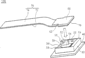
图4为本实用新型的连接器总成的分解示意图;Fig. 4 is an exploded schematic view of the connector assembly of the present invention;
图5为图4中的连接器总成的组合示意图。FIG. 5 is a combined schematic view of the connector assembly in FIG. 4 .
主要元件符号说明Description of main component symbols
10~ZIF连接器10~ZIF connector
10’~连接器10'~connector
12~通道12~Channel
12’~凹陷部12'~depressed part
14~端子14~terminal
20~软性电路板20~flexible circuit board
20’~软性电路板20'~flexible circuit board
22~补强板22~reinforcing board
22’~补强板22'~reinforcing board
24’~连接件24'~connector
50~壳体50~shell
52~容纳部52~Accommodating Department
54~第一开口54~first opening
55~卡合部55~Catching part
56~第二开口56~Second opening
58~止挡部58~stop part
59~端子59~terminal
60~补强板60~reinforcing plate
62~肩部62~shoulder
70~软性电路板70~flexible circuit board
72~第一表面72~first surface
74~第二表面74 ~ second surface
76~接点76~contact
100~连接器总成100~connector assembly
具体实施方式 Detailed ways
图4为本实用新型的连接器总成的一实施例的分解示意图。本实用新型的连接器总成100包括一电路板40、一壳体50、一补强板60以及一软性电路板70。壳体50,如图4所示,呈矩形的立方体,安装于电路板40上。此外,壳体50为绝缘材质。壳体50上形成一大体上呈矩形的凹陷状的容纳部52。此容纳部52具有一第一开口54以及一第二开口56,其中第一开口54朝壳体50的正上方,而第二开口56是相邻于第一开口54,并朝壳体50的侧面。在容纳部52中位于第二开口56处设有二个止挡部58,且止挡部58紧靠容纳部52的侧壁设置。在容纳部52的底部设有多个端子59,其电连接于电路板40。FIG. 4 is an exploded schematic diagram of an embodiment of the connector assembly of the present invention. The
软性电路板70具有一第一表面72以及一第二表面74,而补强板60是结合于软性电路板70的第二表面74,并位于软性电路板70的末端。在第一表面72的末端设有多个接点76,而对应于设于容纳部52的底部则设有多个端子59。端子59可以有多种型态,其主要是能够与平面型态的接点76维持稳定的接触。举例而言,用户识别卡连接器(SIM Card connector)中的端子也可以应用于此端子59中。此外,补强板60具有二肩部62,而使补强板60形成T字形。The
当软性电路板70结合于壳体50时,补强板60从第一开口54进入容纳部52,推压设于容纳部52侧面以及止挡部58的侧面的卡合部55,然后由卡合部55固定于容纳部52中,使端子59与接点76接触,达成电连接,此时,软性电路板70经由第二开口56从壳体50延伸而出,肩部62抵接于止挡部58,使补强板60不会经由第二开口56从容纳部52脱落。此外,由于卡合部55的卡合,补强板60不会经由第一开口54从容纳部52脱落。When the
通过上述的构造,在软性电路板70容易被拖拉的方向,即软性电路板70延伸的方向,可防止软性电路板70从壳体50脱落,如图5所示,可靠度较图1的现有技术的ZIF连接器大,而且厚度比图3的连接器小。Through the above structure, in the direction where the
在本实施例的构造中,由于端子设于软性电路板与补强板相反的一侧,因此补强板可以用金属制成,如此可以增加强度,避免破裂,同时也可改善ESD及EMI的导通。上述的连接器总成100可以应用于各种电子装置中。举例而言,上述的连接器总成100可以应用于手机、个人数字助理(PDA)、超级移动电脑(UMPC)、笔记型电脑等可携式电子装置。然而,连接器总成100也可以应用于桌上型电脑或其他固定式电子装置中。因此,上述的连接器总成100可以应用于各种电子装置中。In the structure of this embodiment, since the terminals are located on the opposite side of the flexible circuit board and the reinforcing plate, the reinforcing plate can be made of metal, which can increase the strength, avoid cracking, and improve ESD and EMI at the same time conduction. The above-mentioned
Claims (6)
Priority Applications (1)
| Application Number | Priority Date | Filing Date | Title |
|---|---|---|---|
| CNU2008201821941U CN201340925Y (en) | 2008-12-16 | 2008-12-16 | Electronic device and connector assembly thereof |
Applications Claiming Priority (1)
| Application Number | Priority Date | Filing Date | Title |
|---|---|---|---|
| CNU2008201821941U CN201340925Y (en) | 2008-12-16 | 2008-12-16 | Electronic device and connector assembly thereof |
Publications (1)
| Publication Number | Publication Date |
|---|---|
| CN201340925Y true CN201340925Y (en) | 2009-11-04 |
Family
ID=41236468
Family Applications (1)
| Application Number | Title | Priority Date | Filing Date |
|---|---|---|---|
| CNU2008201821941U Expired - Lifetime CN201340925Y (en) | 2008-12-16 | 2008-12-16 | Electronic device and connector assembly thereof |
Country Status (1)
| Country | Link |
|---|---|
| CN (1) | CN201340925Y (en) |
Cited By (7)
| Publication number | Priority date | Publication date | Assignee | Title |
|---|---|---|---|---|
| CN101944673A (en) * | 2010-08-01 | 2011-01-12 | 友达光电(苏州)有限公司 | Electric connecting device and display device |
| CN102064404A (en) * | 2010-10-29 | 2011-05-18 | 番禺得意精密电子工业有限公司 | Electric connector assembly |
| CN103765686A (en) * | 2011-08-31 | 2014-04-30 | 山一电机株式会社 | Antenna board connection unit |
| CN105098405A (en) * | 2015-09-24 | 2015-11-25 | 广东欧珀移动通信有限公司 | Circuit board assembly and electronic equipment thereof and assembly identification method |
| CN111541105A (en) * | 2020-04-30 | 2020-08-14 | Oppo(重庆)智能科技有限公司 | Circuit board assembly and electronic device with same |
| WO2021103725A1 (en) * | 2019-11-25 | 2021-06-03 | 华为技术有限公司 | Circuit board assembly and electronic device |
| CN113708121A (en) * | 2020-05-20 | 2021-11-26 | 四零四科技股份有限公司 | Connector device |
-
2008
- 2008-12-16 CN CNU2008201821941U patent/CN201340925Y/en not_active Expired - Lifetime
Cited By (9)
| Publication number | Priority date | Publication date | Assignee | Title |
|---|---|---|---|---|
| CN101944673A (en) * | 2010-08-01 | 2011-01-12 | 友达光电(苏州)有限公司 | Electric connecting device and display device |
| CN102064404A (en) * | 2010-10-29 | 2011-05-18 | 番禺得意精密电子工业有限公司 | Electric connector assembly |
| CN103765686A (en) * | 2011-08-31 | 2014-04-30 | 山一电机株式会社 | Antenna board connection unit |
| CN103765686B (en) * | 2011-08-31 | 2016-06-22 | 山一电机株式会社 | Antenna board connection unit |
| CN105098405A (en) * | 2015-09-24 | 2015-11-25 | 广东欧珀移动通信有限公司 | Circuit board assembly and electronic equipment thereof and assembly identification method |
| WO2021103725A1 (en) * | 2019-11-25 | 2021-06-03 | 华为技术有限公司 | Circuit board assembly and electronic device |
| CN111541105A (en) * | 2020-04-30 | 2020-08-14 | Oppo(重庆)智能科技有限公司 | Circuit board assembly and electronic device with same |
| CN113708121A (en) * | 2020-05-20 | 2021-11-26 | 四零四科技股份有限公司 | Connector device |
| CN113708121B (en) * | 2020-05-20 | 2023-11-03 | 四零四科技股份有限公司 | Connector device |
Similar Documents
| Publication | Publication Date | Title |
|---|---|---|
| US7654829B1 (en) | Electronic device and connector assembly | |
| CN201340925Y (en) | Electronic device and connector assembly thereof | |
| US7534146B2 (en) | Audio jack and PCB assembly having the audio jack | |
| CN101651263B (en) | Wire-to-board connector | |
| US9190747B2 (en) | Circuit-terminal connecting device | |
| CN207517922U (en) | a terminal | |
| CN201113031Y (en) | electrical connector | |
| CN107248679B (en) | Press fixing device and electronic equipment | |
| CN107394527B (en) | USB socket and mobile terminal | |
| CN207398397U (en) | Board-to-Board Connector | |
| CN112636114B (en) | Coaxial connector | |
| CN107645303A (en) | Terminal and deck components | |
| CN106410541A (en) | Electrical connector assembly | |
| US7988490B2 (en) | Retaining clip for connector | |
| CN105281120B (en) | Battery connector | |
| CN101640360A (en) | Electric connector | |
| CN207967161U (en) | A kind of mobile terminal | |
| CN201188463Y (en) | battery connector | |
| CN107482332B (en) | Electric connector assembly and mobile terminal | |
| CN201146265Y (en) | memory card connector | |
| CN218632627U (en) | FPC connector | |
| CN201142497Y (en) | battery connector | |
| CN201946802U (en) | Misplug prevention device of electric connector | |
| CN101752763B (en) | battery connector | |
| CN201207494Y (en) | Battery connector |
Legal Events
| Date | Code | Title | Description |
|---|---|---|---|
| C14 | Grant of patent or utility model | ||
| GR01 | Patent grant | ||
| CX01 | Expiry of patent term |
Granted publication date: 20091104 |
|
| CX01 | Expiry of patent term |