CN201380964Y - A Multifunctional Aerial Robot with Multi-Rotor Legs and Wheels - Google Patents
A Multifunctional Aerial Robot with Multi-Rotor Legs and Wheels Download PDFInfo
- Publication number
- CN201380964Y CN201380964Y CN200920105770U CN200920105770U CN201380964Y CN 201380964 Y CN201380964 Y CN 201380964Y CN 200920105770 U CN200920105770 U CN 200920105770U CN 200920105770 U CN200920105770 U CN 200920105770U CN 201380964 Y CN201380964 Y CN 201380964Y
- Authority
- CN
- China
- Prior art keywords
- rotor
- robot
- wall
- climbing
- drive motor
- Prior art date
- Legal status (The legal status is an assumption and is not a legal conclusion. Google has not performed a legal analysis and makes no representation as to the accuracy of the status listed.)
- Expired - Fee Related
Links
Images

Landscapes
- Manipulator (AREA)
Abstract
本实用新型公开了一种多旋翼腿轮式多功能空中机器人,包括旋翼、旋翼驱动电机、爬壁大腿、爬壁小腿、髋关节驱动电机、膝关节驱动电机、刚度加强环、机器人主体、壁面行走轮、落地支撑杆、旋翼支撑杆。机器人主体为圆形盘状结构,四个旋翼支撑杆沿着机器人主体的下表面四周呈对称分布。旋翼驱动电机用螺钉固定于旋翼支撑杆的外端,旋翼依次固定在旋翼驱动电机的转动轴上。落地支撑杆固定连接于旋翼支撑杆下方。刚度加强环紧固于旋翼支撑杆的上方。本实用新型的机器人,实现了旋翼式飞行器与腿轮式运动机构的融合,机械结构简单、易于实现,机器人在飞行中具有稳定性高、体积小,在爬壁中具有壁面适应性强、越障能力强、适用范围广等优点。
The utility model discloses a multi-rotor leg-wheeled multifunctional aerial robot, which comprises a rotor, a rotor drive motor, a wall-climbing thigh, a wall-climbing calf, a hip joint drive motor, a knee joint drive motor, a rigidity reinforcing ring, a robot main body, and a wall surface. Walking wheels, floor support rods, rotor support rods. The main body of the robot is a circular disk-shaped structure, and the four rotor support rods are symmetrically distributed around the lower surface of the main body of the robot. The rotor drive motor is fixed on the outer end of the rotor support bar with screws, and the rotor is fixed on the rotating shaft of the rotor drive motor in turn. The ground support rod is fixedly connected below the rotor support rod. The rigidity reinforcing ring is fastened on the top of the rotor support bar. The robot of the utility model realizes the integration of the rotor-type aircraft and the leg-wheel type motion mechanism, and has a simple mechanical structure and is easy to realize. It has the advantages of strong barrier ability and wide application range.
Description
技术领域 technical field
本实用新型涉及一种空中机器人,具体涉及一种多旋翼腿轮式多功能空中机器人。The utility model relates to an aerial robot, in particular to a multi-rotor leg-wheeled multifunctional aerial robot.
背景技术 Background technique
目前,许多应用领域都要求飞行器能够进行低空低速的飞行,进行低空作业,并且有良好的机动性和隐蔽性。因此,出现了以单旋翼直升机为平台的飞行器系统。这种单旋翼飞行器能够实现低空低速飞行,也能够完成一定的低空作业,但是,由于采用一个旋翼,所以旋翼的尺寸一般都比较大,工作时比较危险,且单旋翼翼面攻角控制机构复杂,而且是单一失效点,所以故障容度较差。而多旋翼飞行器具有良好的飞行机动性和稳定性,能够完成许多复杂的低空作业,具有垂直起落简单、悬停加速灵活,机动性能强、空中调姿能力强等特点,相对于单旋翼飞行器在相同的运作空间内更易实现较大的推重比,增加任务载荷在总体载荷中的比重。At present, many application fields require the aircraft to be able to fly at low altitude and low speed, perform low-altitude operations, and have good maneuverability and concealment. Therefore, there has been an aircraft system based on a single-rotor helicopter. This kind of single-rotor aircraft can realize low-altitude and low-speed flight, and can also complete certain low-altitude operations. However, due to the use of one rotor, the size of the rotor is generally relatively large, and it is more dangerous when working, and the control mechanism for the angle of attack of the single-rotor wing surface is complicated. , and it is a single point of failure, so the fault tolerance is poor. The multi-rotor aircraft has good flight maneuverability and stability, can complete many complex low-altitude operations, has the characteristics of simple vertical take-off and landing, flexible hover acceleration, strong maneuverability, and strong ability to adjust attitude in the air. It is easier to achieve a larger thrust-to-weight ratio in the same operating space, increasing the proportion of task load in the overall load.
在以飞行器为平台的空中机器人领域的研究中,空中机器人大多只局限于单一的任务,限制了其应用范围。机器人的任务由单一化向多功能化方向发展是空中机器人的一个发展趋势。将飞行和爬壁功能集成于一体,设计兼具飞行和爬壁功能的多功能空中机器人是当前需要解决的问题。In the field of research on aerial robots based on aircraft platforms, aerial robots are mostly limited to a single task, which limits their application range. It is a development trend of aerial robots that the tasks of robots are developed from simplification to multi-function. Integrating flight and wall-climbing functions into one, and designing a multifunctional aerial robot with both flight and wall-climbing functions is a problem that needs to be solved at present.
发明内容 Contents of the invention
本实用新型的目的是为了实现兼具飞行和爬壁功能的多功能空中机器人,采用基于多旋翼飞行平台包含腿轮式爬壁结构的空中机器人结构,提出一种多旋翼腿轮式多功能空中机器人。The purpose of the utility model is to realize a multi-functional aerial robot with both flying and wall-climbing functions. A multi-rotor leg-wheeled multi-functional aerial robot is proposed based on the multi-rotor flight platform including the leg-wheel type wall-climbing structure. robot.
本实用新型的一种多旋翼腿轮式多功能空中机器人,包括旋翼、旋翼驱动电机、爬壁大腿、爬壁小腿、髋关节驱动电机、膝关节驱动电机、刚度加强环、机器人主体、壁面行走轮、落地支撑杆、旋翼支撑杆。A multi-rotor leg-wheeled multifunctional aerial robot of the present invention comprises a rotor, a rotor drive motor, a wall-climbing thigh, a wall-climbing calf, a hip joint drive motor, a knee joint drive motor, a rigidity reinforcing ring, a robot main body, and a wall walking Wheels, landing support rods, rotor support rods.
机器人主体为圆形盘状结构,四个旋翼支撑杆沿着机器人主体的下表面四周呈对称分布,并用螺钉固定于机器人主体上。旋翼驱动电机用螺钉固定于旋翼支撑杆的外端,旋翼依次固定在旋翼驱动电机的转动轴上。且旋翼的旋转平面位于旋翼支撑杆的下方。落地支撑杆固定连接于旋翼支撑杆下方。落地支撑杆上安装弹簧,在机器人落地时起支撑和缓冲作用。刚度加强环与机器人主体同心,紧固于旋翼支撑杆的上方。The main body of the robot is a circular disk-shaped structure, and the four rotor support rods are symmetrically distributed around the lower surface of the main body of the robot, and are fixed on the main body of the robot with screws. The rotor drive motor is fixed on the outer end of the rotor support bar with screws, and the rotor is fixed on the rotating shaft of the rotor drive motor in turn. And the rotation plane of the rotor is located below the rotor support bar. The ground support rod is fixedly connected below the rotor support rod. Springs are installed on the landing support rods to support and buffer the robot when it lands. The rigidity reinforcing ring is concentric with the main body of the robot, and is fastened on the top of the rotor support bar.
爬壁大腿通过髋关节与机器人主体上表面连接,爬壁小腿通过膝关节与爬壁大腿连接,两组爬壁大腿及爬壁小腿位于机器人的一个对称平面内。壁面行走轮位于爬壁小腿的末端。The wall-climbing thighs are connected to the upper surface of the main body of the robot through hip joints, and the wall-climbing legs are connected to the wall-climbing thighs through knee joints. The two sets of wall-climbing thighs and wall-climbing calves are located in a symmetrical plane of the robot. Wall walking wheels are located at the end of the climbing shins.
在髋关节与膝关节上分别固定有髋关节驱动电机、膝关节驱动电机。A hip joint driving motor and a knee joint driving motor are respectively fixed on the hip joint and the knee joint.
为提高机器人的安全性,可以在机器人的外围安装一个保护性装置-保护架。保护架由四个U形铁丝与一个圆环铁丝焊接组成,U形铁丝的一端与机器人的落地支撑杆相固定,另一端焊接圆环铁丝,U形铁丝的高度到达旋翼所在平面。In order to improve the safety of the robot, a protective device-protection frame can be installed on the periphery of the robot. The protective frame is composed of four U-shaped iron wires welded with a circular iron wire. One end of the U-shaped iron wire is fixed to the ground support pole of the robot, and the other end is welded with the circular iron wire. The height of the U-shaped iron wire reaches the plane where the rotor is located.
所述旋翼的翼型采用CLARK-Y翼型。所述旋翼支撑杆外形横截面设置为圆形。所述机器人各旋翼1之间间距大于旋翼1直径的两倍,所述的间距为旋翼的旋转中心的距离。The airfoil of the rotor adopts the CLARK-Y airfoil. The profile cross-section of the rotor support rod is set to be circular. The distance between the
本实用新型的优点在于:The utility model has the advantages of:
(1)本实用新型是一种新型的多旋翼多功能空中机器人,实现了旋翼式飞行器与腿轮式运动机构的融合;(1) The utility model is a novel multi-rotor multi-functional aerial robot, which realizes the integration of the rotor-type aircraft and the leg-wheel type motion mechanism;
(2)机器人的机械结构简单、易于实现;(2) The mechanical structure of the robot is simple and easy to implement;
(3)机器人在飞行中具有稳定性高、体积小等优点;(3) The robot has the advantages of high stability and small size during flight;
(4)机器人在爬壁中具有壁面适应性强、越障能力强、适用范围广等优点。(4) The robot has the advantages of strong wall adaptability, strong obstacle surmounting ability and wide application range in wall climbing.
附图说明 Description of drawings
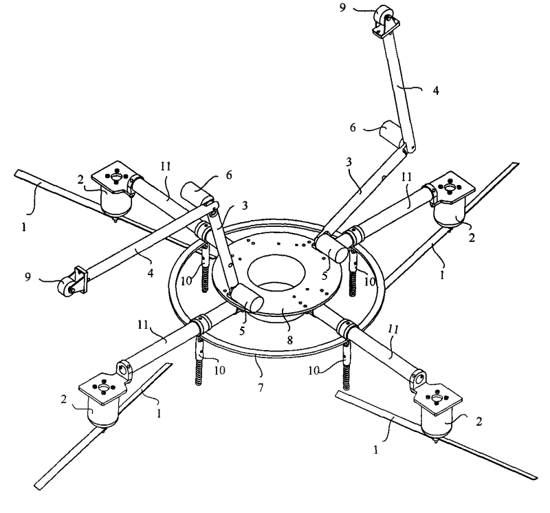
图1是本实用新型一种多旋翼腿轮式多功能空中机器人的结构示意图;Fig. 1 is a structural representation of a multi-rotor leg-wheeled multifunctional aerial robot of the present invention;
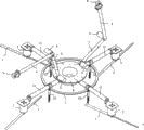
图2是本实用新型一种多旋翼腿轮式多功能空中机器人加保护架后的结构示意图;Fig. 2 is a schematic structural view of a multi-rotor leg-wheeled multifunctional aerial robot of the present invention with a protective frame;
图中:In the picture:
1-旋翼 2-旋翼驱动电机 3-爬壁大腿 4-爬壁小腿1-rotor 2-rotor drive motor 3-climbing thigh 4-climbing calf
5-髋关节驱动电机 6-膝关节驱动电机 7-刚度加强环 8-机器人主体5- Hip drive motor 6- Knee drive motor 7- Rigidity reinforcement ring 8- Robot body
9-壁面行走轮 10-落地支撑杆 11-旋翼支撑杆 12-保护架9-Wall walking wheel 10-Floor support rod 11-Rotor support rod 12-Protection frame
13-U形铁丝 14-圆环铁丝13-U-shaped wire 14-ring wire
具体实施方式 Detailed ways
下面将结合附图对本实用新型作进一步的详细说明。The utility model will be described in further detail below in conjunction with accompanying drawing.
本实用新型是是一种多旋翼腿轮式多功能空中机器人,如图1所示,包括旋翼1、旋翼驱动电机2、爬壁大腿3、爬壁小腿4、髋关节驱动电机5、膝关节驱动电机6、刚度加强环7、机器人主体8、壁面行走轮9、落地支撑杆10、旋翼支撑杆11。The utility model is a multi-rotor leg-wheeled multifunctional aerial robot, as shown in Fig.
如图1所示,机器人主体8为圆形盘状结构,四个旋翼支撑杆11沿着机器人主体8的下表面四周呈对称分布,并用螺钉固定于机器人主体8上。旋翼驱动电机2用螺钉固定于旋翼支撑杆11的外端,旋翼1依次固定在旋翼驱动电机2的转动轴上,其旋转动力由旋翼驱动电机2提供。且旋翼1的旋转平面位于旋翼支撑杆11的下方。落地支撑杆11固定连接于旋翼支撑杆8下方。落地支撑杆11上安装了弹簧,在机器人落地时起支撑和缓冲作用。刚度加强环7与机器人主体8同心,紧固于旋翼支撑杆11的上方,用于加强旋翼支撑杆11的刚度。As shown in FIG. 1 , the robot main body 8 is a circular disk-shaped structure, and four rotor support rods 11 are symmetrically distributed around the lower surface of the robot main body 8 , and are fixed on the robot main body 8 with screws.
爬壁大腿3通过髋关节与机器人主体8上表面连接,爬壁小腿4通过膝关节与爬壁大腿3连接,两组爬壁大腿3及爬壁小腿4位于机器人的一个对称平面内。壁面行走轮9位于爬壁小腿4的末端。壁面行走轮9为被动式行走轮,无电机驱动。The wall-climbing thigh 3 is connected with the upper surface of the robot main body 8 through the hip joint, and the wall-climbing calf 4 is connected with the wall-climbing thigh 3 through the knee joint. Two groups of wall-climbing thighs 3 and the wall-climbing calf 4 are located in a symmetrical plane of the robot. The wall walking wheel 9 is positioned at the end of the wall climbing shank 4 . The wall walking wheel 9 is a passive walking wheel without motor drive.
在髋关节与膝关节上分别固定有髋关节驱动电机5、膝关节驱动电机6。所述爬壁大腿4与机器人主体8之间的髋关节、爬壁大腿4与爬壁小腿3之间的膝关节,转动角度由髋关节驱动电机5、膝关节驱动电机6。动力设备及机载传感器系统置于机器人主体8上,通过对四个旋翼1的联合控制可以精确控制机器人主体8在飞行过程中的姿态角,并为机器人实现爬壁功能提供可靠的保障。A hip joint driving motor 5 and a knee
为提高机器人的安全性,可以在机器人的外围安装一个保护性装置-保护架12。如图2所示,保护架12由四个U形铁丝13与一个圆环铁丝14焊接组成,安装保护架12时,将落地支撑杆10的弹簧去掉,然后将保护架12的U形铁丝13一端与机器人的落地支撑杆10相固定,另一端焊接圆环铁丝14,U形铁丝13的高度到达旋翼1所在平面。增加的保护性装置可以有效避免机器人的旋翼1在飞行过程中碰伤周围的人和物,同时也可以避免机器人在爬壁状态下旋翼1与壁面发生碰撞干涉。为增加机器人的实用性,还可以在机器人的两个爬壁小腿4上增加作业装置,如夹持器等,使机器人在爬壁过程中可以针对壁面上的对象进行简单的夹持作业等操作。For improving the safety of robot, a protective device-
为提高本实用新型的一种多旋翼腿轮式多功能空中机器人在飞行中的气动性能及整体推重比,所述旋翼1的翼型采用CLARK-Y翼型。它的特点是在功率不变的情况下,又采用了宽叶片,小桨叶角的设计,使机器人在一定的条件下达到了最大的推力,提高了机器人整体的推重比。In order to improve the aerodynamic performance and the overall thrust-to-weight ratio of a multi-rotor leg-wheeled multifunctional aerial robot of the present utility model in flight, the airfoil of the
所述旋翼支撑杆11外形横截面设置为圆形,采用N-S方程的数值解法对旋翼绕流场进行数值模拟,模拟旋翼支撑杆11对旋翼流场的影响。分析结果得,旋翼支撑杆外11形横截面设置为圆形可以有效减小旋翼支撑杆对旋翼流场的不利影响。The cross-section of the rotor support rod 11 is set as a circle, and the numerical solution of the N-S equation is used to numerically simulate the flow field around the rotor to simulate the influence of the rotor support rod 11 on the rotor flow field. The analysis results show that setting the outer 11-shaped cross section of the rotor support rod as a circle can effectively reduce the adverse effects of the rotor support rod on the rotor flow field.
所述机器人各旋翼1之间间距大于旋翼1直径的两倍,所述的间距为旋翼1的旋转中心的距离,采用N-S方程的数值解法模拟旋翼之间相互的气动干扰,分析旋翼1之间相互间距对各自旋翼流场的影响。分析结果得,机器人各旋翼1之间间距大于旋翼1直径的两倍,从而有效避免旋翼1相互之间的气动干扰。The distance between the
对所述的旋翼支撑杆11、机器人主体8、爬壁大腿3、爬壁小腿4等部件的重量进行优化。即在满足机器人使用强度的前提下,将上述部件的重量降低到最小。The weight of the components such as the rotor support rod 11, the robot main body 8, the wall-climbing thigh 3, and the wall-climbing shank 4 is optimized. That is, on the premise of satisfying the strength of the robot, the weight of the above-mentioned components should be reduced to a minimum.
Claims (3)
Priority Applications (1)
| Application Number | Priority Date | Filing Date | Title |
|---|---|---|---|
| CN200920105770U CN201380964Y (en) | 2009-03-09 | 2009-03-09 | A Multifunctional Aerial Robot with Multi-Rotor Legs and Wheels |
Applications Claiming Priority (1)
| Application Number | Priority Date | Filing Date | Title |
|---|---|---|---|
| CN200920105770U CN201380964Y (en) | 2009-03-09 | 2009-03-09 | A Multifunctional Aerial Robot with Multi-Rotor Legs and Wheels |
Publications (1)
| Publication Number | Publication Date |
|---|---|
| CN201380964Y true CN201380964Y (en) | 2010-01-13 |
Family
ID=41524438
Family Applications (1)
| Application Number | Title | Priority Date | Filing Date |
|---|---|---|---|
| CN200920105770U Expired - Fee Related CN201380964Y (en) | 2009-03-09 | 2009-03-09 | A Multifunctional Aerial Robot with Multi-Rotor Legs and Wheels |
Country Status (1)
| Country | Link |
|---|---|
| CN (1) | CN201380964Y (en) |
Cited By (14)
| Publication number | Priority date | Publication date | Assignee | Title |
|---|---|---|---|---|
| CN101913311A (en) * | 2010-07-30 | 2010-12-15 | 南京航空航天大学 | Multi-motion-mode robot and its motion modes |
| CN103661931A (en) * | 2013-12-23 | 2014-03-26 | 北京理工大学 | Novel ground motorized composite take-off and landing mechanism applicable to small aircraft |
| CN104118488A (en) * | 2014-08-14 | 2014-10-29 | 北京航空航天大学 | Rolling robot capable of automatically moving |
| CN104682259A (en) * | 2013-12-02 | 2015-06-03 | 国家电网公司 | Cable walking and obstacle-spanning hot-line work tool |
| CN104682258A (en) * | 2013-12-02 | 2015-06-03 | 国家电网公司 | Cable robot walking device |
| CN104875901A (en) * | 2015-05-26 | 2015-09-02 | 苏州绿农航空植保科技有限公司 | Novel anti-collision multi-rotor craft |
| EP2879953A4 (en) * | 2012-08-02 | 2016-04-06 | Neurosciences Res Found | VEHICLE CAPABLE OF MOBILITY ON THE GROUND AND IN THE AIR |
| EP2879952A4 (en) * | 2012-08-02 | 2016-04-13 | Neurosciences Res Found | VEHICLE WHICH CAN STABILIZE A PAYLOAD WHEN IN MOVEMENT |
| CN106809380A (en) * | 2016-12-13 | 2017-06-09 | 华中科技大学 | A kind of four rotor aerial photography aircrafts |
| CN106915454A (en) * | 2017-03-22 | 2017-07-04 | 南京祖航航空科技有限公司 | One kind can flying robot |
| CN108909865A (en) * | 2018-07-13 | 2018-11-30 | 中南大学 | Unmanned plane climbing level robot |
| CN109079820A (en) * | 2018-09-11 | 2018-12-25 | 香港中文大学(深圳) | A kind of detection robot and its rack |
| CN109850026A (en) * | 2019-02-21 | 2019-06-07 | 北京航空航天大学 | It is a kind of to climb wall-gliding machine people with the ala that take down the exhibits |
| CN114265060A (en) * | 2021-12-22 | 2022-04-01 | 河南省国安建筑工程质量检测有限公司 | Engineering structure detection system based on geological radar |
-
2009
- 2009-03-09 CN CN200920105770U patent/CN201380964Y/en not_active Expired - Fee Related
Cited By (16)
| Publication number | Priority date | Publication date | Assignee | Title |
|---|---|---|---|---|
| CN101913311A (en) * | 2010-07-30 | 2010-12-15 | 南京航空航天大学 | Multi-motion-mode robot and its motion modes |
| EP2879953A4 (en) * | 2012-08-02 | 2016-04-06 | Neurosciences Res Found | VEHICLE CAPABLE OF MOBILITY ON THE GROUND AND IN THE AIR |
| EP2879952A4 (en) * | 2012-08-02 | 2016-04-13 | Neurosciences Res Found | VEHICLE WHICH CAN STABILIZE A PAYLOAD WHEN IN MOVEMENT |
| CN104682259A (en) * | 2013-12-02 | 2015-06-03 | 国家电网公司 | Cable walking and obstacle-spanning hot-line work tool |
| CN104682258A (en) * | 2013-12-02 | 2015-06-03 | 国家电网公司 | Cable robot walking device |
| CN103661931A (en) * | 2013-12-23 | 2014-03-26 | 北京理工大学 | Novel ground motorized composite take-off and landing mechanism applicable to small aircraft |
| CN104118488A (en) * | 2014-08-14 | 2014-10-29 | 北京航空航天大学 | Rolling robot capable of automatically moving |
| CN104875901A (en) * | 2015-05-26 | 2015-09-02 | 苏州绿农航空植保科技有限公司 | Novel anti-collision multi-rotor craft |
| CN106809380A (en) * | 2016-12-13 | 2017-06-09 | 华中科技大学 | A kind of four rotor aerial photography aircrafts |
| CN106915454A (en) * | 2017-03-22 | 2017-07-04 | 南京祖航航空科技有限公司 | One kind can flying robot |
| CN108909865A (en) * | 2018-07-13 | 2018-11-30 | 中南大学 | Unmanned plane climbing level robot |
| CN109079820A (en) * | 2018-09-11 | 2018-12-25 | 香港中文大学(深圳) | A kind of detection robot and its rack |
| CN109850026A (en) * | 2019-02-21 | 2019-06-07 | 北京航空航天大学 | It is a kind of to climb wall-gliding machine people with the ala that take down the exhibits |
| CN109850026B (en) * | 2019-02-21 | 2020-11-06 | 北京航空航天大学 | A wall-climbing-gliding robot with retractable wings |
| CN114265060A (en) * | 2021-12-22 | 2022-04-01 | 河南省国安建筑工程质量检测有限公司 | Engineering structure detection system based on geological radar |
| CN114265060B (en) * | 2021-12-22 | 2022-11-01 | 河南省国安建筑工程质量检测有限公司 | Engineering structure detection system based on geological radar |
Similar Documents
| Publication | Publication Date | Title |
|---|---|---|
| CN201380964Y (en) | A Multifunctional Aerial Robot with Multi-Rotor Legs and Wheels | |
| CN101491898A (en) | Multi-rotor wheel-leg type multifunctional air robot and sports programming method thereof | |
| CN205916329U (en) | Coaxial double -oar unmanned vehicles | |
| CN105314105B (en) | Can folding and unfolding wing combined type multi-rotor aerocraft | |
| US7770839B2 (en) | Flight machinery | |
| CN108263599B (en) | Unmanned aerial vehicle, unmanned aerial vehicle descending buffer device | |
| CN103847960B (en) | A kind of composite rotating drives vertically taking off and landing flyer | |
| CN108944302B (en) | A miniature quadrotor hexapod bionic fly-climbing robot | |
| CN104260875B (en) | The resistance to crash feature of agricultural plant protection unmanned plane | |
| CN100391790C (en) | Multi-rotor aerocraft | |
| CN204037909U (en) | Flapping-wing aircraft | |
| CN201816736U (en) | M-shaped flapping wing combined structure under dual-surface work doing and personal flapping wing machine applying structure | |
| RU146302U1 (en) | SPEED COMBINED HELICOPTER | |
| CN104058089B (en) | Some many oars of twin shaft aircraft | |
| CN110294118B (en) | Low-resistance synchronous direct-acting type double-flapping-wing aircraft | |
| CN109896003A (en) | A kind of VTOL is verted three rotor wing unmanned aerial vehicles | |
| CN106741903B (en) | A hybrid drone | |
| CN213168519U (en) | A land-air unmanned aerial vehicle | |
| CN118343321B (en) | A coaxial counter-rotating twin-rotor unmanned helicopter | |
| CN110356552B (en) | Direct-acting double-flapping-wing unmanned aerial vehicle with rotatable blades | |
| CN104386251A (en) | Multi-rotor aircraft body structure | |
| CN106516105A (en) | Aircraft propeller surface regulating mechanism | |
| CN207809771U (en) | Disk like duct quadrotor | |
| CN111591437A (en) | Single-wing aircraft with protection device | |
| CN109455293A (en) | A kind of multi-rotor unmanned aerial vehicle undercarriage and its control method with from steady function |
Legal Events
| Date | Code | Title | Description |
|---|---|---|---|
| C14 | Grant of patent or utility model | ||
| GR01 | Patent grant | ||
| C17 | Cessation of patent right | ||
| CF01 | Termination of patent right due to non-payment of annual fee |
Granted publication date: 20100113 Termination date: 20110309 |