CN201440586U - A flying car for stringing - Google Patents
A flying car for stringing Download PDFInfo
- Publication number
- CN201440586U CN201440586U CN2009201619530U CN200920161953U CN201440586U CN 201440586 U CN201440586 U CN 201440586U CN 2009201619530 U CN2009201619530 U CN 2009201619530U CN 200920161953 U CN200920161953 U CN 200920161953U CN 201440586 U CN201440586 U CN 201440586U
- Authority
- CN
- China
- Prior art keywords
- brake
- flying car
- stringing
- hydraulic
- flying
- Prior art date
- Legal status (The legal status is an assumption and is not a legal conclusion. Google has not performed a legal analysis and makes no representation as to the accuracy of the status listed.)
- Expired - Fee Related
Links
Images


Landscapes
- Valves And Accessory Devices For Braking Systems (AREA)
Abstract
本实用新型公开了一种架线用飞车,用于输电线路架线,包括飞车支架,在飞车支架上有液压系统、驱动轮、分线轮和刹车系统,所述液压系统和驱动轮分别与液压马达连接在一起,所述刹车系统与张紧轮连接。利用本实用新型所提供的架线用飞车,工作过程中,分线轮和驱动轮与导线接触,驱动轮的在液压系统的驱动下驱动轮与导线之间的摩擦力可以使得飞车向前运动,刹车系统可以使得飞车随时停止,这样可以使得在山区或者其他环境恶劣的情况下安装间隔棒时,可以降低安装间隔棒的劳动强度,提高安装间隔板的安全性。本实用新型所提供的架线用飞车,特别适用于输电线路的架线过程中来安装间隔棒。
The utility model discloses a flying car for stringing, which is used for erecting lines of power transmission lines. The hydraulic motors are connected together, and the brake system is connected with the tensioning pulley. Utilizing the flying car for stringing provided by the utility model, during the working process, the wire dividing wheel and the driving wheel are in contact with the wire, and the friction between the driving wheel and the wire driven by the hydraulic system can make the flying car move forward , The brake system can stop the flying car at any time, which can reduce the labor intensity of installing the spacer and improve the safety of the installation of the spacer when installing the spacer in mountainous areas or other harsh environments. The flying car for stringing provided by the utility model is especially suitable for installing spacers in the stringing process of power transmission lines.
Description
技术领域 technical field
本实用新型涉及一种架线用飞车,属于输电线路架线施工机具领域。The utility model relates to a flying car for stringing, which belongs to the field of construction equipment for wire stringing of power transmission lines.
背景技术 Background technique
输电线路一般采用高压输电的形式。输电就是将发电站发出的电能,通过输电线路输送到各个用电地方。根据输电距离的远近,采用不同的高电压。具体情况请见表1。Transmission lines generally adopt the form of high-voltage transmission. Electricity transmission is the transmission of electric energy generated by power stations to various places where electricity is consumed through transmission lines. According to the distance of power transmission, different high voltages are used. See Table 1 for details.
表1Table 1
在输电过程中,由于电流通过导线时有一部分电能转变为热能而损耗,并且电压越低,热能消耗越高,因此需要采用高压输电,从这一方面来讲,输电电压越高,输电的距离就可以越远。基于此,目前我国国家电网在推进800~1000千伏以上的超高压输电线路。In the process of power transmission, because a part of the electric energy is converted into heat energy and lost when the current passes through the wire, and the lower the voltage, the higher the heat energy consumption, so high-voltage power transmission is required. From this point of view, the higher the power transmission voltage, the longer the power transmission distance. as far as possible. Based on this, my country's State Grid is currently promoting ultra-high voltage transmission lines above 800-1000 kV.
超高压输电线路距离往往很长,可能跨越上千公里,跨越的地形可能是平原,也可能是水域和山区。间隔棒的重量大约有30千克左右,因此,安装间隔棒的劳动强度和安全性都存在问题,尤其是在山区地带,这种问题表现的尤其突出。EHV transmission lines are often very long, and may span thousands of kilometers, and the terrain may be plains, waters and mountains. The weight of spacer bar has about 30 kilograms, therefore, all there is problem in the labor intensity and safety of installing spacer bar, especially in mountain area, this problem performance is outstanding especially.
实用新型内容 Utility model content
针对上述缺陷,本实用新型解决的技术问题在于,提供一种架线用飞车,其能够降低安装间隔棒的劳动强度,提高安装间隔棒的安全性。In view of the above defects, the technical problem solved by the utility model is to provide a flying car for stringing, which can reduce the labor intensity of installing the spacer and improve the safety of installing the spacer.
为了解决以上的技术问题,本实用新型提供以下的技术方案:In order to solve the above technical problems, the utility model provides the following technical solutions:
一种架线用飞车,用于输电线路架线,包括飞车支架,在飞车支架上有液压系统、驱动轮、分线轮和刹车系统,所述液压系统和驱动轮分别与液压马达连接在一起,所述刹车系统与张紧轮连接。A flying car for stringing, which is used for wiring of power transmission lines, includes a flying car support, and a hydraulic system, a driving wheel, a splitting wheel and a brake system are arranged on the flying car support, and the hydraulic system and the driving wheel are respectively connected with a hydraulic motor , the brake system is connected with the tensioning wheel.
本实用新型所提供的架线用飞车,工作过程中,分线轮和驱动轮与导线接触,驱动轮的在液压系统的驱动下驱动轮与导线之间的摩擦力可以使得飞车向前运动,刹车系统可以使得飞车随时停止,这样可以使得在山区或者其他环境恶劣的情况下安装间隔棒时,可以降低安装间隔棒的劳动强度,提高安装间隔板的安全性。In the flying car for stringing provided by the utility model, during the working process, the splitting wheel and the driving wheel are in contact with the wire, and the friction between the driving wheel and the wire under the drive of the hydraulic system can make the flying car move forward. The braking system can stop the flying car at any time, which can reduce the labor intensity of installing the spacer and improve the safety of installing the spacer when installing the spacer in mountainous areas or other harsh environments.
优选地,所述液压系统包括油箱、汽油机、液压泵和液压管路,所述汽油机与所述液压泵通过液压管路连通,所述油箱与所述汽油机通过液压管路连通,所述液压泵与所述液压马达连接在一起。Preferably, the hydraulic system includes a fuel tank, a gasoline engine, a hydraulic pump and a hydraulic pipeline, the gasoline engine communicates with the hydraulic pump through a hydraulic pipeline, the fuel tank communicates with the gasoline engine through a hydraulic pipeline, and the hydraulic pump connected with the hydraulic motor.
优选地,所述液压系统通过螺栓固定在所述飞车支架上。Preferably, the hydraulic system is fixed on the flying car support by bolts.
优选地,所述刹车系统与所述飞车支架通过销轴和旋转轴连接在一起。Preferably, the braking system is connected with the flying car bracket through a pin shaft and a rotating shaft.
优选地,所述液压马达和驱动轮分别与所述飞车支架通过螺栓、轮轴和轴承连接在一起。Preferably, the hydraulic motor and the driving wheel are respectively connected to the flying car bracket through bolts, wheel shafts and bearings.
优选地,所述刹车系统包括刹车凹片、与刹车凹片相配合的刹车凸片、刹车手柄和长轴,所述刹车凹片、所述与刹车凹片相配合的刹车凸片和所述刹车手柄在所述长轴上,所述刹车凸片和所述刹车手柄连接,所述张紧轮与所述刹车凹片连接在一起,所述张紧轮与所述长轴连接在一起。Preferably, the brake system includes brake concave pads, brake convex pads matched with brake concave pads, a brake handle and a long shaft, the brake concave pads, the brake convex pads matched with brake concave pads and the The brake handle is on the long axis, the brake lug is connected with the brake handle, the tension wheel is connected with the brake concave piece, and the tension wheel is connected with the long shaft.
优选地,所述刹车凸片与所述刹车手柄通过螺栓连接在一起。Preferably, the brake lug and the brake handle are connected together by bolts.
优选地,所述张紧轮与所述刹车凹片通过螺栓连接在一起。Preferably, the tensioning wheel and the brake concave pad are connected together by bolts.
优选地,所述张紧轮与所述长轴通过轴承连接在一起。Preferably, the tensioning wheel and the long shaft are connected together through bearings.
优选地,所述分线轮通过螺栓、轮轴和轴承连接在一起。Preferably, the thread dividing wheels are connected together through bolts, axles and bearings.
利用本实用新型所提供的架线用飞车,工作过程中,分线轮和驱动轮与导线接触,驱动轮的在液压系统的驱动下驱动轮与导线之间的摩擦力可以使得飞车向前运动,刹车系统可以使得飞车随时停止,这样可以使得在山区或者其他环境恶劣的情况下安装间隔棒时,可以降低安装间隔棒的劳动强度,提高安装间隔板的安全性。Utilizing the flying car for stringing provided by the utility model, during the working process, the wire dividing wheel and the driving wheel are in contact with the wire, and the friction between the driving wheel and the wire driven by the hydraulic system can make the flying car move forward , The brake system can stop the flying car at any time, which can reduce the labor intensity of installing the spacer and improve the safety of the installation of the spacer when installing the spacer in mountainous areas or other harsh environments.
本实用新型所提供的架线用飞车,特别适用于输电线路的架线过程中来安装间隔棒。The flying car for stringing provided by the utility model is especially suitable for installing spacers in the stringing process of power transmission lines.
附图说明 Description of drawings
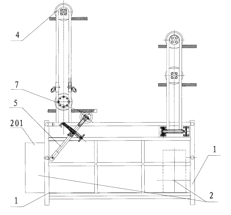
图1是实施例1提供的架线用飞车的主视图。Fig. 1 is the front view of the flying car for stringing provided by Embodiment 1.
图2是实施例1提供的架线用飞车的左视图。Fig. 2 is a left side view of the flying car for stringing provided by Embodiment 1.
图3是实施例1提供的架线用飞车的刹车系统的结构图。Fig. 3 is a structural diagram of the braking system of the flying car for stringing provided by Embodiment 1.
图4是图3所示的刹车系统的左视剖视图。Fig. 4 is a left sectional view of the braking system shown in Fig. 3 .
图5是图3中箭头附件B向的放大视图。Fig. 5 is an enlarged view in the direction of arrow B in Fig. 3 .
图中各标记为:Each is marked in the figure as:
1——飞车支架,2——液压系统,201——油箱,202——汽油机,203——液压泵,3——驱动轮,4——分线轮,5——刹车系统,501——刹车凹片,502——与刹车凹片向配合的刹车凸片,503——刹车手柄,504——长轴,6——液压马达,7——张紧轮。1——Flying car bracket, 2—Hydraulic system, 201—Fuel tank, 202—Gasoline engine, 203—Hydraulic pump, 3—Drive wheel, 4—Splitting wheel, 5—Brake system, 501— Brake concave plate, 502—brake convex plate that cooperates with brake concave plate, 503—brake handle, 504—major shaft, 6—hydraulic motor, 7—tension wheel.
具体实施方式 Detailed ways
为了本领域的技术人员能够更好地理解本实用新型所提供的技术方案,下面结合具体实施例进行阐述。In order for those skilled in the art to better understand the technical solutions provided by the utility model, the following will be described in conjunction with specific embodiments.
实施例1Example 1
本实施例提供一种架线用飞车,用于输电线路架线。This embodiment provides a flying car for stringing, which is used for stringing a power transmission line.
请参见图1和图2,图1是实施例1提供的架线用飞车的主视图;图2是实施例1提供的架线用飞车的左视图。Please refer to Fig. 1 and Fig. 2, Fig. 1 is a front view of the flying car for stringing provided by
本实施例中的架线用飞车,用于输电线路架线,包括飞车支架1,在飞车支架1上有液压系统2、驱动轮3、分线轮4和刹车系统5,所述液压系统2和驱动轮3分别与液压马达6连接在一起,所述刹车系统5与张紧轮7连接。The flying car used for stringing in the present embodiment is used for power transmission line stringing, and includes a
所述液压系统2包括油箱201、汽油机202、液压泵203和液压管路,所述汽油机202与所述液压泵203通过液压管路连通,所述油箱201与所述汽油机202通过液压管路连通,所述液压泵203与所述液压马达6连接在一起。液压管路图中未示出,液压管路采用常用的液压管路即可,并且与其他部件连通的方式也是较为常规的连通方式即可,不需要有特殊的要求,相关工程技术人员可以随意选择液压管路,只要能够满足连通的要求即可。The
液压系统2通过螺栓固定在飞车支架1上。这里所要表述的思想为,将液压系统固定在飞车支架上,使得其可以正常工作,并不代表所有的液压系统组成部分都要固定在飞车支架上,例如作为液压系统组成部分之一的液压管路,就不一定要通过螺栓等方式固定在飞车支架上,如果液压管路为金属管路,那么其自身的力学性能已经完全可以使得其随着支架来回移动而不会出现相互位移,因此主要能够使得液压系统正常工作,那么固定的方式也是可以作出调整的。The
分线轮4通过螺栓、轮轴和轴承连接在一起。本实施例中,有六个分线轮,两个驱动轮,工作过程中,分线轮和驱动轮都与导线接触,并且有摩擦力产生。至于分线轮和驱动轮的数目,则是可以变化了,一般的变换形式还有,两个分线轮搭配两个驱动轮,或者四个分线轮搭配两个驱动轮。Line dividing
请参见图3,图3是实施例1提供的架线用飞车的刹车系统的结构图。刹车系统5包括刹车凹片501、与刹车凹片相配合的刹车凸片502、刹车手柄503和长轴504,所述刹车凹片、所述与刹车凹片相配合的刹车凸片和所述刹车手柄在所述长轴上,所述刹车凸片502和所述刹车手柄503连接,所述张紧轮7与所述刹车凹片501连接在一起,所述张紧轮7与所述长轴504连接在一起。Please refer to FIG. 3 . FIG. 3 is a structural diagram of the braking system of the flying car for stringing provided by Embodiment 1. The
请参见图4,图4是图3所示的刹车系统的左视剖视图。如图所示,所述刹车凸片502与所述刹车手柄503通过螺栓连接在一起。Please refer to FIG. 4 . FIG. 4 is a left sectional view of the braking system shown in FIG. 3 . As shown in the figure, the
请参见图5,图5是图3中箭头附件B向的放大视图。Please refer to FIG. 5 , which is an enlarged view in the direction of arrow B in FIG. 3 .
刹车手柄可以在长轴上自由旋转。The brake lever can rotate freely on the long axis.
所述张紧轮可以张紧驱动轮与导线,调节导线与驱动轮之间的压力。The tension wheel can tension the driving wheel and the wire, and adjust the pressure between the wire and the driving wheel.
在本实施例中,所述张紧轮与所述刹车凹片通过螺栓连接,并且同时,张紧轮与长轴通过轴承连接在一起。In this embodiment, the tensioning wheel is connected to the brake concave plate through bolts, and at the same time, the tensioning wheel and the long shaft are connected together through bearings.
本实施例中提供的架线用飞车的工作原理为:The working principle of the flying car for stringing provided in this embodiment is:
(1)行走原理:架线用飞车行走时,其驱动轮和分线轮分别压在八根导线上,发动汽油机启动液压系统,液压泵开始工作,液压泵驱动液压马达转动,带动驱动轮旋转或者有旋转的趋势,驱动轮会收到一个摩擦力;此时刹车系统处于非刹车状态,也就是刹车凹片和刹车凸片处于分离状态,通过调整张紧轮的高度高低,也就是调节驱动轮与导线之间的摩擦力的大小,当摩擦力达到一定程度时,架线飞车就会相对导线开始运动。(1) Walking principle: when the flying car is used for stringing, the driving wheel and the splitting wheel are respectively pressed on the eight wires, the gasoline engine is started to start the hydraulic system, the hydraulic pump starts to work, the hydraulic pump drives the hydraulic motor to rotate, and drives the driving wheel to rotate Or there is a tendency to rotate, and the driving wheel will receive a friction force; at this time, the brake system is in a non-braking state, that is, the brake concave pad and the brake tab are in a separated state, by adjusting the height of the tension wheel, that is, adjusting the driving force The magnitude of the friction between the wheel and the wire, when the friction reaches a certain level, the flying car will start to move relative to the wire.
当架线用飞车行走至指定位置后,停止,然后,就可以进行间隔棒的安装。After the flying car travels to the designated position for the stringing, stop, and then, the spacer rod can be installed.
(2)刹车原理:需要刹车时,关闭汽油机,则液压马达停止工作,驱动轮不再旋转,此时旋转刹车手柄,使得刹车凸片与刹车凹片啮合至张紧轮不转动,调节张紧轮的高度,当张紧轮、驱动轮和导线之间的摩擦力到达一定程度时,飞车就会停止运动。(2) Braking principle: When braking is required, turn off the gasoline engine, the hydraulic motor will stop working, and the driving wheel will no longer rotate. At this time, turn the brake handle to make the brake tabs and brake concaves mesh until the tension wheel does not rotate, and adjust the tension. The height of the wheel, when the friction between the tension wheel, the driving wheel and the wire reaches a certain level, the flying car will stop moving.
(3)架线用飞车通过悬垂串的操作过程:当架线用飞车到达悬垂串时,首先通过手拉链条葫芦将架线用飞车吊起,通过操作人员操作手拉链条葫芦使得支架的一部分通过悬垂串,然后将通过的那部分支架装在导线上,主要是驱动轮或者分线轮,然后以同样的方法可以使得另一部分支架通过导线。(3) The operation process of the flying car for stringing passing through the suspension string: when the flying car for stringing reaches the hanging string, firstly the flying car for stringing is lifted by the hand chain hoist, and the operator operates the hand chain chain hoist to make a part of the bracket Pass through the hanging string, and then install the passing part of the bracket on the wire, mainly the driving wheel or the splitting wheel, and then use the same method to make the other part of the bracket pass through the wire.
利用本实用新型所提供的架线用飞车,工作过程中,分线轮和驱动轮与导线接触,驱动轮的在液压系统的驱动下驱动轮与导线之间的摩擦力可以使得飞车向前运动,刹车系统可以使得飞车随时停止,这样可以使得在山区或者其他环境恶劣的情况下安装间隔棒时,可以降低安装间隔棒的劳动强度,提高安装间隔板的安全性。Utilizing the flying car for stringing provided by the utility model, during the working process, the wire dividing wheel and the driving wheel are in contact with the wire, and the friction between the driving wheel and the wire driven by the hydraulic system can make the flying car move forward , The brake system can stop the flying car at any time, which can reduce the labor intensity of installing the spacer and improve the safety of the installation of the spacer when installing the spacer in mountainous areas or other harsh environments.
本实用新型所提供的架线用飞车,特别适用于输电线路的架线过程中来安装间隔棒。The flying car for stringing provided by the utility model is especially suitable for installing spacers in the stringing process of power transmission lines.
以上所述仅是本实用新型的优选实施方式,应当指出,对于本技术领域的普通技术人员来说,在不脱离本实用新型原理的前提下,还可以做出若干改进和润饰,这些改进和润饰也应视为本实用新型的保护范围。The above is only a preferred embodiment of the utility model, it should be pointed out that for those of ordinary skill in the art, without departing from the principle of the utility model, some improvements and modifications can also be made, these improvements and Retouching should also be regarded as the scope of protection of the present utility model.
Claims (10)
Priority Applications (1)
| Application Number | Priority Date | Filing Date | Title |
|---|---|---|---|
| CN2009201619530U CN201440586U (en) | 2009-07-09 | 2009-07-09 | A flying car for stringing |
Applications Claiming Priority (1)
| Application Number | Priority Date | Filing Date | Title |
|---|---|---|---|
| CN2009201619530U CN201440586U (en) | 2009-07-09 | 2009-07-09 | A flying car for stringing |
Publications (1)
| Publication Number | Publication Date |
|---|---|
| CN201440586U true CN201440586U (en) | 2010-04-21 |
Family
ID=42545244
Family Applications (1)
| Application Number | Title | Priority Date | Filing Date |
|---|---|---|---|
| CN2009201619530U Expired - Fee Related CN201440586U (en) | 2009-07-09 | 2009-07-09 | A flying car for stringing |
Country Status (1)
| Country | Link |
|---|---|
| CN (1) | CN201440586U (en) |
Cited By (2)
| Publication number | Priority date | Publication date | Assignee | Title |
|---|---|---|---|---|
| CN102231490A (en) * | 2011-04-02 | 2011-11-02 | 武汉奋进科技有限公司 | Manned traveling locomotive for high-voltage transmission line |
| CN104078891A (en) * | 2014-07-24 | 2014-10-01 | 国家电网公司 | Self-traction type conducting wire high-altitude electrified maintenance vehicle for electric transmission line |
-
2009
- 2009-07-09 CN CN2009201619530U patent/CN201440586U/en not_active Expired - Fee Related
Cited By (3)
| Publication number | Priority date | Publication date | Assignee | Title |
|---|---|---|---|---|
| CN102231490A (en) * | 2011-04-02 | 2011-11-02 | 武汉奋进科技有限公司 | Manned traveling locomotive for high-voltage transmission line |
| CN102231490B (en) * | 2011-04-02 | 2014-06-25 | 武汉奋进科技有限公司 | Manned traveling locomotive for high-voltage transmission line |
| CN104078891A (en) * | 2014-07-24 | 2014-10-01 | 国家电网公司 | Self-traction type conducting wire high-altitude electrified maintenance vehicle for electric transmission line |
Similar Documents
| Publication | Publication Date | Title |
|---|---|---|
| CN106352158B (en) | Pipeline transportation and installation method for pipe gallery | |
| CN105350926A (en) | Super-capacitor energy storage type electric workover rig | |
| CN102434155A (en) | Coal mining machine and rocker arm transmission system thereof | |
| CN201440586U (en) | A flying car for stringing | |
| CN107161162A (en) | A kind of drive system used for rail vehicle and rail vehicle | |
| CN203204971U (en) | Unpowered and automatic advertisement turning-over gateway rod | |
| CN102490730A (en) | Device for driving bogie of electric locomotive | |
| CN112590855A (en) | Electric driving subway shunting locomotive | |
| CN204737676U (en) | Electric block auxiliary brake | |
| CN204490799U (en) | Lead truck system | |
| CN205472384U (en) | Drum hoisting machine of singly restricting | |
| CN204823760U (en) | Monkey running gear | |
| CN202911466U (en) | Guiding wheel and autorailer | |
| CN203359656U (en) | Vertical-horizontal dual-purpose constant tension paying-off trolley | |
| CN203472657U (en) | Tooling for blade transport vehicle of wind-driven generator and transport vehicle | |
| CN202911490U (en) | Power guiding wheel and autorailer | |
| CN202320314U (en) | Bogie drive mechanism of electric locomotive | |
| CN206942659U (en) | A kind of flywheel energy storage self power generation Self propelled type well repairing machine | |
| CN205189467U (en) | Chain over -and -under type stereo garage lift system transmission | |
| CN220331184U (en) | Guiding device of installation equipment | |
| CN205737707U (en) | A kind of novel combination type crossbeam | |
| CN221739714U (en) | Direct-connection driving device and braking structure suitable for tire-type gantry crane | |
| CN205025379U (en) | Electronic workover rig of on -vehicle compound power | |
| CN201236094Y (en) | Efficiency compensating mechanism for multi-pulley block in series | |
| CN201770417U (en) | Driving traveling wheel unit of trolley of crane |
Legal Events
| Date | Code | Title | Description |
|---|---|---|---|
| C14 | Grant of patent or utility model | ||
| GR01 | Patent grant | ||
| CF01 | Termination of patent right due to non-payment of annual fee |
Granted publication date: 20100421 Termination date: 20180709 |
|
| CF01 | Termination of patent right due to non-payment of annual fee |