CN201611706U - Electric connector - Google Patents
Electric connector Download PDFInfo
- Publication number
- CN201611706U CN201611706U CN2010201084853U CN201020108485U CN201611706U CN 201611706 U CN201611706 U CN 201611706U CN 2010201084853 U CN2010201084853 U CN 2010201084853U CN 201020108485 U CN201020108485 U CN 201020108485U CN 201611706 U CN201611706 U CN 201611706U
- Authority
- CN
- China
- Prior art keywords
- terminal
- cover plate
- side wall
- cover
- bending
- Prior art date
- Legal status (The legal status is an assumption and is not a legal conclusion. Google has not performed a legal analysis and makes no representation as to the accuracy of the status listed.)
- Expired - Lifetime
Links
- 238000005452 bending Methods 0.000 claims abstract description 19
- 238000003466 welding Methods 0.000 claims abstract description 7
- 229910000679 solder Inorganic materials 0.000 description 6
- 238000010586 diagram Methods 0.000 description 4
- UQMRAFJOBWOFNS-UHFFFAOYSA-N butyl 2-(2,4-dichlorophenoxy)acetate Chemical compound CCCCOC(=O)COC1=CC=C(Cl)C=C1Cl UQMRAFJOBWOFNS-UHFFFAOYSA-N 0.000 description 2
- 239000012212 insulator Substances 0.000 description 2
- 238000004519 manufacturing process Methods 0.000 description 2
- 238000000465 moulding Methods 0.000 description 2
- 230000009286 beneficial effect Effects 0.000 description 1
- 238000004891 communication Methods 0.000 description 1
- 238000013461 design Methods 0.000 description 1
- 238000002513 implantation Methods 0.000 description 1
- 238000009434 installation Methods 0.000 description 1
- 238000009413 insulation Methods 0.000 description 1
- 239000002184 metal Substances 0.000 description 1
- 238000000034 method Methods 0.000 description 1
- 230000001681 protective effect Effects 0.000 description 1
- 238000011160 research Methods 0.000 description 1
- 238000012552 review Methods 0.000 description 1
Images

Landscapes
- Connector Housings Or Holding Contact Members (AREA)
Abstract
Description
技术领域:Technical field:
本实用新型涉及连接器技术领域,特指一种可即插即拔的电连接器。The utility model relates to the technical field of connectors, in particular to a plug-and-pull electrical connector.
背景技术:Background technique:
电连接器,可实现快速插接使用,目前已广泛应用于电子产品中,尤其是电脑、通讯器材等。电连接器可结合在线材使用,也可结合在主板上使用。对于结合在主板的形式,为了降低连接器组装高度,一般采用卧式设计,即电连接器为平躺布置,这时,端子的焊脚一般需要弯折引出。而传统的电连接器,其端子折弯部位仅是依靠护板上的端子孔或端子护槽给予横向定位,而缺少竖向定位,因而在上板焊接时,出现有焊脚向上内缩的情况,影响上板操作。Electrical connectors, which can be quickly plugged in, have been widely used in electronic products, especially computers and communication equipment. Electrical connectors can be used in conjunction with wires or on motherboards. For the form combined on the main board, in order to reduce the assembly height of the connector, a horizontal design is generally adopted, that is, the electrical connector is arranged in a flat position. At this time, the solder legs of the terminals generally need to be bent and drawn out. However, in traditional electrical connectors, the bending position of the terminal only depends on the terminal hole or the terminal protection groove on the protective plate to give horizontal positioning, but lacks vertical positioning. The situation will affect the board operation.
本申请人有鉴于上述习知电连接器结构之缺失与不便之处,秉持着研究创新、精益求精之精神,利用其专业眼光和专业知识,研究出一种可有效防止焊脚内缩的电连接器。In view of the lack and inconvenience of the above-mentioned conventional electrical connector structure, the applicant adheres to the spirit of research, innovation and excellence, and uses his professional vision and professional knowledge to develop an electrical connection that can effectively prevent the solder pins from shrinking. device.
实用新型内容:Utility model content:
本实用新型的目的在于提供一种结构优化,可防止焊脚内缩,利于上板操作的电连接器。The purpose of the utility model is to provide an electric connector with an optimized structure, which can prevent the welding legs from retracting, and facilitates the operation on the board.
为达到上述目的,本实用新型采用如下技术方案:In order to achieve the above object, the utility model adopts the following technical solutions:
一种电连接器,包括绝缘主体、数端子、后盖及外壳,绝缘主体设有朝后延伸的左右侧壁及位于左右侧壁内的护板;数端子植入于绝缘主体上,端子的焊脚向下弯折并依附护板定位;后盖嵌设于左右侧壁之间,后盖具有一上顶盖板和一竖向盖板,在两盖板内侧设有咬合的锯齿,锯齿适当支顶端子的折弯部;所述上顶盖板的内侧面抵压相应端子的折弯部的上顶面;外壳套接绝缘主体,并设有扣脚固定后盖。An electrical connector, comprising an insulating body, a digital terminal, a back cover and a shell, the insulating main body is provided with left and right side walls extending backward and guard plates located in the left and right side walls; the digital terminals are implanted on the insulating main body, and the terminals The welding leg is bent downward and positioned with the guard plate; the back cover is embedded between the left and right side walls, the back cover has an upper cover plate and a vertical cover plate, and there are occlusal sawtooth on the inner side of the two cover plates, the sawtooth The bending part of the appropriate support terminal; the inner surface of the upper top cover plate is pressed against the upper top surface of the bending part of the corresponding terminal; the outer shell is sleeved on the insulating main body, and a buckle foot is provided to fix the back cover.
所述后盖左右侧端设有外凸的耳扣,耳扣对应左右侧壁上的扣槽嵌入安装,外壳的扣脚固定住耳扣。The left and right side ends of the back cover are provided with protruding ear buckles, which are embedded in corresponding to the buckle grooves on the left and right side walls, and the buckle feet of the shell fix the ear buckles.
于后盖的左右侧端的端面上还设有外凸的筋条,筋条紧贴左右侧壁的内侧面插入组装。Protruding ribs are also provided on the end surfaces of the left and right side ends of the back cover, and the ribs are inserted and assembled close to the inner surfaces of the left and right side walls.
所述后盖的上顶盖板和竖向盖板相互垂直,呈L形。The top cover plate and the vertical cover plate of the rear cover are perpendicular to each other and are L-shaped.
本实用新型主要是在连接器后端设一后盖,后盖配合护板定位端子折弯部,其中,后盖内侧具有锯齿适当支顶端子的折弯部,以及设一上顶盖板,由上顶盖板的内侧面抵压相应端子的折弯部的上顶面,由此达到对方位限制端子折弯部,防止焊脚内缩,利于上板操作。The utility model is mainly provided with a rear cover at the rear end of the connector, and the rear cover cooperates with the guard plate to position the terminal bending part, wherein, the inner side of the rear cover has a sawtooth bending part suitable for supporting the top terminal, and an upper cover plate is provided, The inner surface of the upper top cover plate is pressed against the upper top surface of the bending part of the corresponding terminal, so as to limit the bending part of the terminal to the azimuth, prevent the welding leg from retracting, and facilitate the operation of the upper board.
本实用新型再一优点是结构优化,利于成型制作,制作成本低。Another advantage of the utility model is that the structure is optimized, which is beneficial to molding and production, and the production cost is low.
附图说明:Description of drawings:
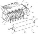
附图1为本实用新型结构示意图;Accompanying drawing 1 is the structural representation of the utility model;
附图2、3为图1之结构的内部结构剖视示意图;Accompanying drawing 2,3 are the internal structure sectional schematic diagrams of the structure of Fig. 1;
附图4为本实用新型局部结构立体分解示意图;Accompanying drawing 4 is the three-dimensional exploded schematic view of the local structure of the utility model;
附图5为本实用新型的绝缘主体结构示意图;Accompanying drawing 5 is the structure schematic diagram of the insulation main body of the present utility model;
附图6、7为后盖的立体结构示意图。Accompanying drawing 6, 7 is the three-dimensional structure schematic diagram of back cover.
具体实施方式:Detailed ways:
为了使审查委员能对本实用新型之目的、特征及功能有更进一步了解,兹举较佳实施例并配合图式详细说明如下:In order to enable the review committee to have a further understanding of the purpose, features and functions of the present utility model, the preferred embodiments are hereby given in detail with the accompanying drawings as follows:
请参阅图1至图7所示,系为本实用新型之较佳实施例的结构示意图,本实用新型是有关一种可即插即拔的电连接器,其是由绝缘主体10、数端子20、后盖30及外壳40组合构成。Please refer to Fig. 1 to Fig. 7, which are structural schematic diagrams of preferred embodiments of the present utility model. The utility model relates to a plug-and-pull electrical connector, which is composed of an insulating
图5所示,绝缘主体10的前端形成插接端,供端子的接触部安置,在绝缘主体10还设有相应的端子组装孔13,供端子固定组装,在绝缘主体10后端设有朝后延伸的左右侧壁11及位于左右侧壁11内的护板12,护板12上设有端子护槽121,而左右侧壁11上设有剖切构造的扣槽111。As shown in Figure 5, the front end of the
数端子20采用植入方式顺着端子组装孔13组装于绝缘主体10上,接触部安置在绝缘主体10的前端上,端子的焊脚21向下弯折并依附护板12定位。本实施例中,端子20分成上下两组,下组端子的焊脚21向下弯折后其折弯部依附于护板12上的端子护槽121内定位,而上组端子的焊脚21向下弯折后依附于护板12外侧端面上定位。The
图6、7所示,后盖30嵌设于左右侧壁11之间,后盖30具有一上顶盖板31和一竖向盖板32,在两盖板31、32内侧设有咬合的锯齿33,锯齿33适当支顶端子的折弯部;所述上顶盖板31的内侧面抵压相应端子的折弯部的上顶面;锯齿33即可辅助定位端子,还有效衔接上顶盖板31和竖向盖板32,满足一体成型制作,结构性好;本实施例中,上顶盖板31和竖向盖板32相互垂直,呈L形。上顶盖板31有效定位上组端子的折弯部,可达到防止焊脚内缩的作用,使焊脚可平齐插入主板上的孔中,提升上板操作的效率和质量。后盖30的左右侧端设有外凸的耳扣34及筋条35,以满足嵌装之要求。As shown in Figures 6 and 7, the
外壳40为一金属壳体,其套接绝缘主体10,并设有扣脚41固定后盖30。The shell 40 is a metal shell, which is sleeved on the insulating
组装时,先是将端子20组装于绝缘主体10上,然后再将后盖30嵌入左右侧壁11之间,后盖30左右侧端的耳扣34对应左右侧壁11上的扣槽111嵌入安装,而后盖30的左右侧端的端面上的筋条35紧贴左右侧壁11的内侧面插入组装,达到紧配合;最后再将外壳40套接绝缘主体10,并由外壳的扣脚41内弯固定住耳扣34,即完成组装。图2、3所示,组装好后,后盖30的上顶盖板31、竖向盖板32及锯齿33在不同方位定位端子20,增加端子折弯部的结构性,并有效防止焊脚内缩。When assembling, the
Claims (4)
Priority Applications (1)
| Application Number | Priority Date | Filing Date | Title |
|---|---|---|---|
| CN2010201084853U CN201611706U (en) | 2010-01-29 | 2010-01-29 | Electric connector |
Applications Claiming Priority (1)
| Application Number | Priority Date | Filing Date | Title |
|---|---|---|---|
| CN2010201084853U CN201611706U (en) | 2010-01-29 | 2010-01-29 | Electric connector |
Publications (1)
| Publication Number | Publication Date |
|---|---|
| CN201611706U true CN201611706U (en) | 2010-10-20 |
Family
ID=42962341
Family Applications (1)
| Application Number | Title | Priority Date | Filing Date |
|---|---|---|---|
| CN2010201084853U Expired - Lifetime CN201611706U (en) | 2010-01-29 | 2010-01-29 | Electric connector |
Country Status (1)
| Country | Link |
|---|---|
| CN (1) | CN201611706U (en) |
-
2010
- 2010-01-29 CN CN2010201084853U patent/CN201611706U/en not_active Expired - Lifetime
Similar Documents
| Publication | Publication Date | Title |
|---|---|---|
| CN203135087U (en) | Electric connector | |
| CN202585914U (en) | Electric connector | |
| CN201130749Y (en) | battery connector | |
| CN202474337U (en) | Electrical connector assembly | |
| CN204885560U (en) | Warp-resistant receptacle electronic connectors | |
| CN201611706U (en) | Electric connector | |
| CN202454775U (en) | Micro USB 3.0 Dual Row Receptacle Connector | |
| CN207967364U (en) | Steady type USB Type-C connectors | |
| CN201315359Y (en) | Novel board-connected electric connector | |
| CN201623279U (en) | Board connects USB connector | |
| CN202678586U (en) | Pad type electrical connector | |
| CN202333206U (en) | Conductive terminal of cable connector | |
| CN201887202U (en) | Electric connector component | |
| CN201113129Y (en) | battery connector | |
| TWI451635B (en) | Socket electrical connector | |
| TWI451636B (en) | Electrical connector | |
| CN201061011Y (en) | Combined electrical connector | |
| CN200994033Y (en) | Improved plug connector | |
| CN204156225U (en) | Connectors with an integrated structure of shielding sheet and snap spring arm | |
| CN205828720U (en) | Solder-friendly USB Type‑C receptacle connector | |
| CN201812966U (en) | USB connector strengthening structure | |
| CN215343087U (en) | Electrical connector | |
| CN201893463U (en) | Metal shell structure of HDMI connector | |
| CN201383587Y (en) | Electric connector assembling structure | |
| CN215343114U (en) | electrical connector |
Legal Events
| Date | Code | Title | Description |
|---|---|---|---|
| C14 | Grant of patent or utility model | ||
| GR01 | Patent grant | ||
| CX01 | Expiry of patent term |
Granted publication date: 20101020 |
|
| CX01 | Expiry of patent term |