CN201629534U - Circuit terminal box - Google Patents

Circuit terminal box Download PDF

Info

Publication number
CN201629534U
CN201629534U CN2010201248410U CN201020124841U CN201629534U CN 201629534 U CN201629534 U CN 201629534U CN 2010201248410 U CN2010201248410 U CN 2010201248410U CN 201020124841 U CN201020124841 U CN 201020124841U CN 201629534 U CN201629534 U CN 201629534U
Authority
CN
China
Prior art keywords
elastic buckle
cover
box
bottom box
surface cover
Prior art date
Legal status (The legal status is an assumption and is not a legal conclusion. Google has not performed a legal analysis and makes no representation as to the accuracy of the status listed.)
Expired - Fee Related
Application number
CN2010201248410U
Other languages
Chinese (zh)
Inventor
李波
Current Assignee (The listed assignees may be inaccurate. Google has not performed a legal analysis and makes no representation or warranty as to the accuracy of the list.)
Zhongshan Jefferson Electronics Co ltd
Original Assignee
Zhongshan Jefferson Electronics Co ltd
Priority date (The priority date is an assumption and is not a legal conclusion. Google has not performed a legal analysis and makes no representation as to the accuracy of the date listed.)
Filing date
Publication date
Application filed by Zhongshan Jefferson Electronics Co ltd filed Critical Zhongshan Jefferson Electronics Co ltd
Priority to CN2010201248410U priority Critical patent/CN201629534U/en
Application granted granted Critical
Publication of CN201629534U publication Critical patent/CN201629534U/en
Anticipated expiration legal-status Critical
Expired - Fee Related legal-status Critical Current

Links

Images

Landscapes

  • Connection Or Junction Boxes (AREA)
  • Connections Arranged To Contact A Plurality Of Conductors (AREA)
  • Casings For Electric Apparatus (AREA)

Abstract

本实用新型提供一种安装和维修都相当方便的线路终端盒,该种线路终端盒包括侧面设有出线孔的底盒以及底盒上的面盖,所述底盒相对的两个侧面内壁设有向上伸出的弹性卡扣,所述面盖内设有与所述弹性卡扣配合的卡接部,所述弹性卡扣的卡爪向侧边伸出。根据本实用新型提出的线路终端盒,安装时只要将面盖对好底盒,轻轻按下面盖使底盒侧壁上的弹性卡扣卡住面盖的卡接部就可以完成安装;需要维修时,只要将对应弹性卡扣位置处的底盒侧壁轻轻往里一按,就可以使弹性卡扣向内侧移动,从而脱离面盖的卡接部,把面盖打开,使用起来相当方便。

Figure 201020124841

The utility model provides a line terminal box which is convenient to install and maintain. The line terminal box comprises a bottom box with a wire outlet hole on the side and a surface cover on the bottom box. The inner walls of the two opposite sides of the bottom box are provided with elastic buckles extending upward. The surface cover is provided with a clamping part cooperating with the elastic buckle, and the clamping claw of the elastic buckle extends to the side. According to the line terminal box proposed by the utility model, when installing, the surface cover can be installed by aligning the bottom box with the surface cover and gently pressing the surface cover so that the elastic buckle on the side wall of the bottom box clamps the clamping part of the surface cover; when maintenance is needed, the side wall of the bottom box at the corresponding elastic buckle position can be gently pressed inward to move the elastic buckle inward, thereby disengaging from the clamping part of the surface cover, and the surface cover can be opened, which is very convenient to use.

Figure 201020124841

Description

A kind of line terminal box
Technical field
The utility model relates to a kind of technical field of electric appliance casing, is specifically related to a kind of line terminal box
Background technology
As shown in Figure 1, existing line terminal box, comprise power terminal box, telephone terminal box, network terminal box, CATV terminal box etc., the mode that cover and end box all adopt screw to clench, screw hole on the cover need be aimed at the screw hole on the end box during installation, stamp screw with the screwdriver that is fit to again and fix, installing and keeping in repair all wastes time and energy.
The utility model content
The purpose of this utility model is to provide all line terminal boxes quite easily of a kind of installation and maintenance.
Line terminal of the present utility model box comprises that the side is provided with the end box of wire hole and the cover on the end box, key is that two relative side inner walls of box of the described end are provided with the Elastic buckle that protrudes upward, be provided with the Access Division that cooperates with described Elastic buckle in the described cover, the claw of described Elastic buckle stretches out to side.
According to the line terminal box that the utility model proposes, during installation if with cover to box of the good end, installation just can be finished in the Access Division that makes Elastic buckle on the end box sidewall block cover by lower cover gently; When needing repairing,, Elastic buckle is moved to the inside, thereby break away from the Access Division of cover, cover is opened as long as the end box sidewall of corresponding Elastic buckle position one is pressed gently inward, very convenient to use.
Described Access Division is the groove of the claw position of the corresponding Elastic buckle of cover inwall, or the through hole of corresponding Elastic buckle position on the cover.Elastic buckle can be stuck on the groove of cover inwall by claw, or through hole and its claw that Elastic buckle passes on the cover block cover.
The claw of the Elastic buckle on the side inner walls of box of the described end is longer than the claw of the Elastic buckle on another side inner walls, be beneficial to like this cover firmly is connected with end box, short claw is easy to open, when opening, long claw and the Access Division that is mated form a rotating shaft, can not influence opening of cover.
Upwards be provided with guide post in the box of the described end, the corresponding position is provided with the bullport that cross sectional shape conforms to guide post on the described cover, only need make the guide post on the bullport aligning end box on the cover when installing like this, just can make the Access Division of cover aim at Elastic buckle, and then cover pressed, it is quite convenient to use.
Be provided with column with threaded hole in the box of the described end, the position at corresponding screwed hole on the described cover is provided with through hole, like this when the Elastic buckle on the end box damages, can also be unlikely to change box of the whole end with the fixing cover of screw.
Line terminal of the present utility model box installation and removal maintenance does not need to use other instruments, installs simple, easy to maintenance.
Description of drawings
Fig. 1 is the mounting structure schematic diagram of traditional circuit terminal box;
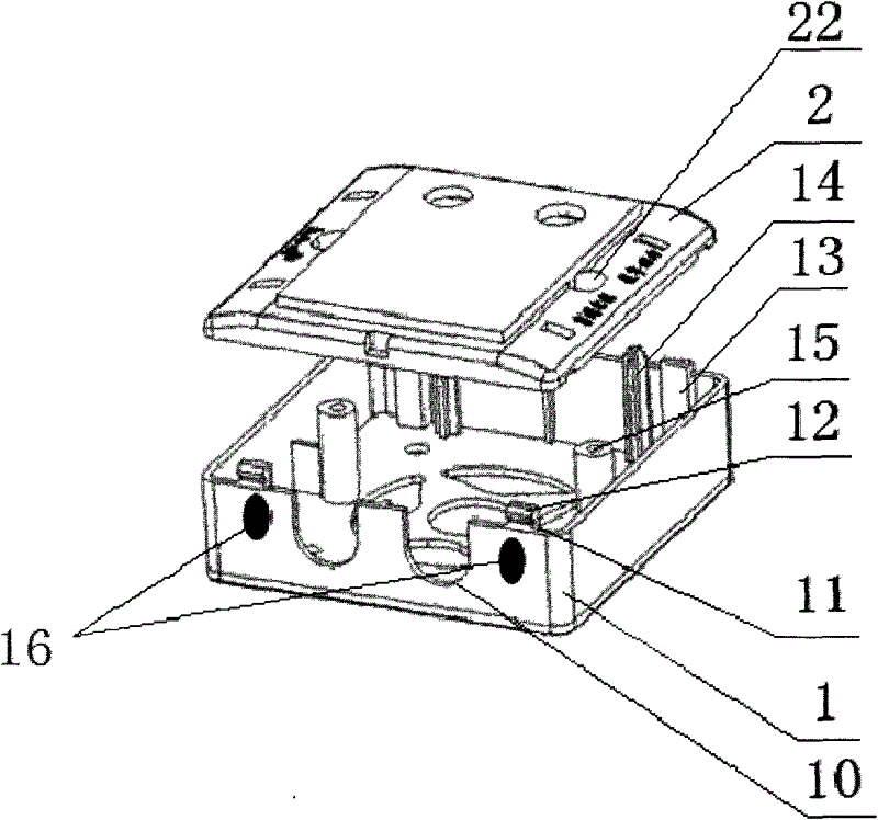
Fig. 2 is the mounting structure schematic diagram of of the present utility model lid and bottom box;
Fig. 3 is the structure enlarged drawing of Elastic buckle of the present utility model and a kind of cooperation of cover;
Fig. 4 is the another kind of structure enlarged drawing that cooperates of Elastic buckle of the present utility model and cover.
Embodiment
Describe embodiment of the present utility model in detail below in conjunction with accompanying drawing.
As Fig. 2, line terminal of the present utility model box comprises that the side is provided with the end box 1 of wire hole 10 and the cover 2 on the end box 1, box 1 two relative side inner walls in the end are provided with the Elastic buckle 11 and 13 that protrudes upward, be provided with the Access Division that cooperates with Elastic buckle 11 in the cover 2, the claw of described Elastic buckle 11 12 stretches out to side.
As Fig. 3, the Access Division of cover 2 is the groove 21 of claw 12 positions of the corresponding Elastic buckle 11 of cover 2 inwalls.As long as with 2 pairs of good ends of cover box 1, the groove 21 that makes Elastic buckle 11 on end box 1 sidewall block cover 2 inwalls by lower cover 2 just can be finished installation gently during installation; When needing repairing, if with end box 1 sidewall (16 liang of stain positions among Fig. 2) of corresponding Elastic buckle 11 positions gently inward once by the groove 21 that can make Elastic buckle 11 disengaging covers 2 inwalls, cover 2 is opened, very convenient to use.
As Fig. 4, as the another kind of execution mode of the utility model, the Access Division of cover 2 is the through hole 21 of corresponding Elastic buckle 11 positions on the cover 2.As long as with 2 pairs of good ends of cover box 1, by lower cover 2, make the Elastic buckle 11 on end box 1 sidewall pass the through hole 21 of correspondence position on the cover 2 gently during installation, and make the claw 12 of Elastic buckle 11 block cover 2 just can to finish installation; The aperture of through hole 21 is greater than the thickness of Elastic buckle 11, to reserve the space that Elastic buckle 11 moves, when needing repairing like this, as long as with end box 1 sidewall (16 liang of stain positions among Fig. 2) of corresponding Elastic buckle 11 positions gently inward once by making Elastic buckle 11 mobile to the inside, thereby break away from the through hole 21 on the cover 2, claw 12 no longer blocks cover 2, thereby cover 2 is opened, and is very convenient to use.
As Fig. 2, the claw of Elastic buckle 13 is longer than the claw of Elastic buckle 11, the claw of Elastic buckle 13 is longer, be beneficial to cover 2 firmly is connected with end box 1, the claw of Elastic buckle 11 is shorter, is easy to open, when opening, the claw of Elastic buckle 13 and the Access Division that is mated form a rotating shaft, can not influence opening of cover 2.Upwards be provided with guide post 14 in the end box 1, cover 2 is provided with the bullport (bullport does not draw among the figure) that cross sectional shape conforms to guide post 14 in the corresponding position, only need make the guide post 14 on the bullport aligning end 1 box on the cover 2 when installing like this, just can make the Access Division of cover 2 aim at Elastic buckle, and then cover 2 pressed, it is quite convenient to use.Be provided with column with threaded hole 15 in the end box 1, the position of corresponding screwed hole is provided with through hole 22 on the described cover 2, like this when the Elastic buckle on the end box 1 damages, can also be unlikely to change end box 1 with the fixing cover 2 of screw.
Line terminal of the present utility model box installation and removal maintenance does not need to use other instruments, installs simple, easy to maintenance.

Claims (5)

1.一种线路终端盒,包括侧面设有出线孔的底盒以及底盒上的面盖,其特征在于所述底盒相对的两个侧面内壁设有向上伸出的弹性卡扣,所述面盖内设有与所述弹性卡扣配合的卡接部,所述弹性卡扣的卡爪向侧边伸出。1. A line terminal box, comprising a bottom box with an outlet hole on the side and a cover on the bottom box, characterized in that the inner walls of the two opposite sides of the bottom box are provided with upwardly protruding elastic buckles, the There is a clamping part matched with the elastic buckle inside the face cover, and the claws of the elastic buckle protrude to the side. 2.根据权利要求1所述的线路终端盒,其特征在于所述卡接部为面盖内壁对应弹性卡扣的卡爪位置的凹槽,或者是面盖上对应弹性卡扣位置的通孔。2. The line terminal box according to claim 1, wherein the clamping part is a groove on the inner wall of the cover corresponding to the position of the claw of the elastic buckle, or a through hole on the cover corresponding to the position of the elastic buckle . 3.根据权利要求1或2所述的线路终端盒,其特征在于所述底盒的一个侧面内壁上的弹性卡扣的卡爪比另一个侧面内壁上的弹性卡扣的卡爪长。3. The line terminal box according to claim 1 or 2, characterized in that the claw of the elastic buckle on the inner wall of one side of the bottom box is longer than the claw of the elastic buckle on the inner wall of the other side. 4.根据权利要求1或2所述的线路终端盒,其特征在于所述底盒内向上设有引导柱,所述面盖上对应位置处设有截面形状与引导柱相符的引导孔。4. The line terminal box according to claim 1 or 2, wherein the bottom box is provided with a guide column upward, and the corresponding position of the cover is provided with a guide hole whose cross-sectional shape conforms to the guide column. 5.根据权利要求1或2所述的线路终端盒,其特征在于所述底盒内设有带螺纹孔的立柱,所述面盖在对应螺纹孔的位置处设有通孔。5. The line terminal box according to claim 1 or 2, wherein the bottom box is provided with a column with a threaded hole, and the cover is provided with a through hole at a position corresponding to the threaded hole.
CN2010201248410U 2010-03-01 2010-03-01 Circuit terminal box Expired - Fee Related CN201629534U (en)

Priority Applications (1)

Application Number Priority Date Filing Date Title
CN2010201248410U CN201629534U (en) 2010-03-01 2010-03-01 Circuit terminal box

Applications Claiming Priority (1)

Application Number Priority Date Filing Date Title
CN2010201248410U CN201629534U (en) 2010-03-01 2010-03-01 Circuit terminal box

Publications (1)

Publication Number Publication Date
CN201629534U true CN201629534U (en) 2010-11-10

Family

ID=43060933

Family Applications (1)

Application Number Title Priority Date Filing Date
CN2010201248410U Expired - Fee Related CN201629534U (en) 2010-03-01 2010-03-01 Circuit terminal box

Country Status (1)

Country Link
CN (1) CN201629534U (en)

Cited By (3)

* Cited by examiner, † Cited by third party
Publication number Priority date Publication date Assignee Title
CN103427380A (en) * 2012-05-15 2013-12-04 刘彩声 Multi-purpose terminal box
CN105514634A (en) * 2013-07-18 2016-04-20 中山市丰申电器有限公司 A junction box for use with a switch/socket panel
CN107845993A (en) * 2017-12-24 2018-03-27 浙江柳晶整流器有限公司 A kind of easy-to-dismount low-voltage electrical apparatus Junction box assembly

Cited By (3)

* Cited by examiner, † Cited by third party
Publication number Priority date Publication date Assignee Title
CN103427380A (en) * 2012-05-15 2013-12-04 刘彩声 Multi-purpose terminal box
CN105514634A (en) * 2013-07-18 2016-04-20 中山市丰申电器有限公司 A junction box for use with a switch/socket panel
CN107845993A (en) * 2017-12-24 2018-03-27 浙江柳晶整流器有限公司 A kind of easy-to-dismount low-voltage electrical apparatus Junction box assembly

Similar Documents

Publication Publication Date Title
DE602006019493D1 (en) Electrical passage to a junction box connection system
CN201629534U (en) Circuit terminal box
CN202524224U (en) A junction box and a motor for its application
CN110529424B (en) Decorative panel assembly and household appliance
CN202523315U (en) Anti-prying lead seal structure of electric energy meter
CN203483291U (en) Electric rice cooker cover and electric rice cooker
CN204666695U (en) The overall cellular-type electrical energy metering tank of SMC
CN203950757U (en) A kind of termination, circuit breaker and breaker assembly of circuit breaker
CN202273520U (en) Upper hinge device for refrigerator and refrigerator with upper hinge device
CN201590604U (en) A plug-in power module box structure
CN204330845U (en) A kind of plug type installs the ammeter box of ammeter
CN202403483U (en) Portable refrigerator
CN204406048U (en) Intelligent watch
CN201111949Y (en) Ceiling electric appliance housing body fixing device
CN203932896U (en) A kind of embedded junction box
CN201167211Y (en) Body of outdoor power box
CN203465327U (en) Voice reading device of electric-meter box
CN203193232U (en) An outdoor junction box
CN201117928Y (en) Safe waterproof socket
CN203249219U (en) Lamp panel assembly and air conditioner indoor unit
CN202690693U (en) Screw cover and its assembly structure with base, air conditioner
CN208205341U (en) A kind of sensor stand and mobile air conditioner
CN203596471U (en) Installation box having two installation ways and cooperated electrical accessory
CN203761169U (en) Limiting structure of motor support and air conditioner
CN105281221A (en) Cover body split type distribution box

Legal Events

Date Code Title Description
C14 Grant of patent or utility model
GR01 Patent grant
C17 Cessation of patent right
CF01 Termination of patent right due to non-payment of annual fee

Granted publication date: 20101110

Termination date: 20120301