CN201655863U - Hybrid battery exchange device - Google Patents
Hybrid battery exchange device Download PDFInfo
- Publication number
- CN201655863U CN201655863U CN2010201147903U CN201020114790U CN201655863U CN 201655863 U CN201655863 U CN 201655863U CN 2010201147903 U CN2010201147903 U CN 2010201147903U CN 201020114790 U CN201020114790 U CN 201020114790U CN 201655863 U CN201655863 U CN 201655863U
- Authority
- CN
- China
- Prior art keywords
- battery
- storage tank
- tank group
- accommodating groove
- ccontaining
- Prior art date
- Legal status (The legal status is an assumption and is not a legal conclusion. Google has not performed a legal analysis and makes no representation as to the accuracy of the status listed.)
- Expired - Fee Related
Links
- 230000004308 accommodation Effects 0.000 description 16
- 238000006073 displacement reaction Methods 0.000 description 4
- 238000010586 diagram Methods 0.000 description 2
- 238000012986 modification Methods 0.000 description 2
- 230000004048 modification Effects 0.000 description 2
- 230000035939 shock Effects 0.000 description 2
- 230000007547 defect Effects 0.000 description 1
- 238000005516 engineering process Methods 0.000 description 1
- 238000003780 insertion Methods 0.000 description 1
- 230000037431 insertion Effects 0.000 description 1
- 238000009434 installation Methods 0.000 description 1
- 238000000034 method Methods 0.000 description 1
Images




Classifications
-
- Y—GENERAL TAGGING OF NEW TECHNOLOGICAL DEVELOPMENTS; GENERAL TAGGING OF CROSS-SECTIONAL TECHNOLOGIES SPANNING OVER SEVERAL SECTIONS OF THE IPC; TECHNICAL SUBJECTS COVERED BY FORMER USPC CROSS-REFERENCE ART COLLECTIONS [XRACs] AND DIGESTS
- Y02—TECHNOLOGIES OR APPLICATIONS FOR MITIGATION OR ADAPTATION AGAINST CLIMATE CHANGE
- Y02E—REDUCTION OF GREENHOUSE GAS [GHG] EMISSIONS, RELATED TO ENERGY GENERATION, TRANSMISSION OR DISTRIBUTION
- Y02E60/00—Enabling technologies; Technologies with a potential or indirect contribution to GHG emissions mitigation
- Y02E60/10—Energy storage using batteries
Landscapes
- Electric Propulsion And Braking For Vehicles (AREA)
Abstract
Description
技术领域technical field
本实用新型涉及一种混合式电池交换装置,尤其涉及一种应用于电动车辆电池定点交换,及具有混合电池充电或单纯电池容置操作模式,以存取与交换充电电池操作的装置。The utility model relates to a hybrid battery exchange device, in particular to a fixed-point battery exchange device for electric vehicles, which has a hybrid battery charging or simple battery storage operation mode for accessing and exchanging rechargeable batteries.
背景技术Background technique
电动车辆为极欲取代高污及耗油汽车的绿能代步交通工具之一,但无论是电动机车或电动汽车,最主要的关键组件即为作为行驶动力能源的充电电池,有鉴于设置充电站的设备及土地成本太高,电动车辆充电站无法普及与大量设置,是阻滞电动车辆普遍化的问题根源。Electric vehicles are one of the green energy vehicles that are eager to replace high-pollution and fuel-guzzling vehicles. However, whether it is an electric vehicle or an electric vehicle, the most important key component is the rechargeable battery as the power source for driving. In view of the installation of charging stations The cost of equipment and land is too high, and electric vehicle charging stations cannot be popularized and installed in large numbers, which is the root cause of the problem that hinders the popularization of electric vehicles.
因此,有许多解决的方案因此因运而生,诸如中国台湾专利公报第412095号「移动式电池充电及交换装置」新型专利案,则初步揭示关于充电电池交换的雏型技术,但诸如此类现有的车载式移动电池交换站的硬件结构,在行驶路途中,因行驶路面的颠簸不平产生震动,导致箱内用来移动充电电池的机械手臂(robot arm)进行充电电池的位移操作时,易失去精准度,而引起当机故障的问题,故此种现有车载式移动电池交换站的设计,在机械操作精准度及防震度的问题,在无法被作有效及低成本解决的前,并不易被大量应用及提供给产业利用。Therefore, there are many solutions arising therefrom, such as China Taiwan Patent Publication No. 412095 "Mobile Battery Charging and Exchange Device" novel patent case, which initially reveals the prototype technology about rechargeable battery exchange, but such existing The hardware structure of the vehicle-mounted mobile battery exchange station, on the road, is shaken due to the bumpy road surface, which causes the robot arm (robot arm) used to move the rechargeable battery in the box to perform the displacement operation of the rechargeable battery. Therefore, the design of the existing vehicle-mounted mobile battery exchange station is not easy to be solved until the problems of mechanical operation accuracy and shock resistance cannot be solved effectively and at low cost. A large number of applications and provide for industrial use.
另外,如考虑以定点驻在式的电池交换系统,如中台湾国专利公报第344159号「集中式电池保管暨充电装置」新型专利案,虽无上述移动式电池充电及交换装置所会产生的机械手臂精准度、防震度与成本高的问题与缺点,但缺乏因应充电电池交换业务量频繁时所需的机动与调度灵活度,例如:在使用电动车辆数量与密度较高的地点,会有较频繁与超量的充电电池交换量,则上述现有定点驻在式充电电池交换系统与结构,将无法实时快速提供充足的充电电池供应量,缺乏充电电池调度应变能力,造成使用者于充电电池交换上的不便与困扰,亦无法符合产业利用的需求与经济效益。In addition, if a fixed-point battery exchange system is considered, such as the new patent case of "Centralized Battery Storage and Charging Device" in Taiwan Patent Publication No. 344159, although there is no problem that the above-mentioned mobile battery charging and exchange device will produce The problems and shortcomings of the precision, shock resistance and high cost of the robotic arm, but it lacks the mobility and scheduling flexibility required to cope with frequent rechargeable battery exchange business volumes. For example, in places with a high number and density of electric vehicles, there will be More frequent and excessive rechargeable battery exchanges, the above-mentioned existing fixed-point resident rechargeable battery exchange system and structure will not be able to provide sufficient rechargeable battery supply in real time and quickly, and lack the ability to dispatch rechargeable batteries. The inconvenience and troubles of battery exchange cannot meet the needs and economic benefits of industrial utilization.
实用新型内容Utility model content
本实用新型所要解决的主要技术问题在于,克服现有技术存在的易产生机械手臂震动移位失去精确度的问题与缺点,以及现有固定驻在式交换装置池无法机动与实时快速应付大量充电电池交换的问题,而无法提供给产业作有效的利用的缺陷,而提供一种混合式电池交换装置,可快速补充大量充电电池,且不会产生电池移动插拔手臂震动移位影响精确度的问题与缺点,可以完全消除现有车载移动式或固定定点驻在式交换装置的问题与缺点,同时并兼具此两者的优点,以解决电动车辆长久以来积存的充电电池充电与交换的问题。The main technical problem to be solved by the utility model is to overcome the problems and shortcomings of the prior art that are prone to vibration, displacement and loss of accuracy of the mechanical arm, and the existing fixed resident exchange device pool cannot be maneuvered and quickly cope with a large amount of charging in real time The problem of battery exchange, and the defect that it cannot be provided to the industry for effective use, and a hybrid battery exchange device is provided, which can quickly replenish a large number of rechargeable batteries, and will not cause vibration and displacement of the battery moving plug arm to affect accuracy. The problems and shortcomings can completely eliminate the problems and shortcomings of the existing vehicle-mounted mobile or fixed-point resident switching devices, and at the same time have the advantages of both, so as to solve the long-standing problem of rechargeable battery charging and switching in electric vehicles .
本实用新型解决其技术问题所采用的技术方案是:The technical scheme that the utility model solves its technical problem adopts is:
一种混合式电池交换装置,其特征在于,包括:至少一电池容置列模块,包括若干数个第一容置槽组及第二容置槽组,该第一容置槽组及第二容置槽组于周缘设有若干第一连接部及第二连接部,使第一容置槽组或第二容置槽组之间借该第一连接部及第二连接部对应连结而组合,该第一容置槽组及第二容置槽组内设有若干电池容置槽,该第一容置槽组的电池容置槽中设有至少一充电座,以供至少一充电电池容置充电,该第二容置槽组的电池容置槽供至少一充电电池容置;至少一对轨道,设于该电池容置列模块一侧上、下端;至少一电池移动插拔手臂,设于两轨道之间,沿该两轨道的轨迹移动于两电池容置列模块的各第一容置槽组或第二容置槽组之间,借由该电池移动插拔手臂对各第一容置槽组的各电池容置槽内的充电电池或第二容置槽组的各电池容置槽内的各充电电池进行移出或储放的交换操作。A hybrid battery exchange device, characterized in that it includes: at least one battery storage column module, including several first storage tank groups and second storage tank groups, the first storage tank group and the second storage tank group A number of first connecting parts and second connecting parts are provided on the periphery of the receiving tank group, so that the first receiving tank group or the second receiving tank group can be combined through the corresponding connection of the first connecting part and the second connecting part , the first and second accommodating groove groups are provided with a plurality of battery accommodating grooves, and at least one charging base is provided in the battery accommodating groove of the first accommodating groove group for at least one rechargeable battery Accommodating and charging, the battery accommodating slot of the second accommodating slot group is for accommodating at least one rechargeable battery; at least one pair of rails are arranged at the upper and lower ends of one side of the battery accommodating row module; at least one battery moving insertion arm , set between the two rails, move along the tracks of the two rails between the first or second accommodating slot groups of the two battery accommodating row modules, and use the battery to move the plugging arm to each The rechargeable batteries in the battery accommodating slots of the first accommodating slot group or the rechargeable batteries in the battery accommodating slots of the second accommodating slot group are exchanged for removal or storage.
前述的混合式电池交换装置,其中第一容置槽组的第一连接部为插梢。In the aforementioned hybrid battery exchange device, the first connection portion of the first accommodation slot set is a pin.
前述的混合式电池交换装置,其中第一容置槽组的第二连接部为凹槽。In the aforementioned hybrid battery exchange device, the second connecting portion of the first accommodating tank set is a groove.
前述的混合式电池交换装置,其中第二容置槽组的第一连接部为插梢。In the aforementioned hybrid battery exchange device, the first connecting portion of the second accommodating slot set is a pin.
前述的混合式电池交换装置,其中第二容置槽组的第二连接部为凹槽。In the aforementioned hybrid battery exchange device, the second connecting portion of the second accommodating tank set is a groove.
前述的混合式电池交换装置,其中电池移动插拔手臂包括:至少一导轨,连结于两轨道间;至少一导轨驱动器,驱动该导轨沿该轨道的轨迹进行上、下垂直移动;及至少一电池抓取器,结合于该导轨上,使该电池抓取器沿该导轨轨迹进行前、后轴向移动,且该电池抓取器并向左或右,朝两侧的电池容置列模块中的各第一容置槽组的电池容置槽或第二容置槽组的各电池容置槽内抓取充满电量的充电电池或将交换的电量耗尽的充电电池送入电池容置列模块中的各第一容置槽组的电池容置槽或第二容置槽组的各电池容置槽内容置。The aforementioned hybrid battery exchange device, wherein the battery moving plug arm includes: at least one guide rail, connected between two rails; at least one guide rail driver, driving the guide rail to move vertically up and down along the track of the rail; and at least one battery The grabber is combined with the guide rail, so that the battery grabber can move forward and backward axially along the track of the guide rail, and the battery grabber can move to the left or right, toward the batteries on both sides of the row module Grab a fully charged rechargeable battery from the battery storage slots of each of the first storage slot groups or each battery storage slot of the second storage slot group or send the exchanged rechargeable batteries that have run out of power into the battery storage row The battery accommodating grooves of each first accommodating groove group or the battery accommodating grooves of the second accommodating groove group in the module are placed in.
本实用新型的混合式电池交换装置的功效,在于借由电池容置列模块中的第一容置槽组或第二容置槽组的第一连接部与第二连接部的对应连结结构,让使用者依据充电电池交换量变化予以作灵活组合调配,可以在定点位置不需车载移动,即可快速补充大量充电电池,且不会产生电池移动插拔手臂震动移位影响精确度的问题与缺点,可以完全消除上述现有车载移动式或固定定点驻在式交换装置的问题与缺点,同时并兼具此两者的优点,以解决电动车辆长久以来积存的充电电池充电与交换的问题。The efficacy of the hybrid battery exchange device of the present invention lies in the corresponding connection structure between the first connection part and the second connection part of the first storage tank group or the second storage tank group in the battery storage row module, It allows users to make flexible combination and allocation according to the change of rechargeable battery exchange volume, and can quickly replenish a large number of rechargeable batteries at a fixed point without moving the vehicle, and there will be no problems with the vibration and displacement of the battery moving, plugging and unplugging arms that affect accuracy. Disadvantages can completely eliminate the problems and shortcomings of the above-mentioned existing vehicle-mounted mobile or fixed-point resident switching devices, and at the same time combine the advantages of both to solve the long-standing problem of rechargeable battery charging and switching for electric vehicles.
附图说明Description of drawings
下面结合附图和实施例对本实用新型进一步说明。Below in conjunction with accompanying drawing and embodiment the utility model is further described.
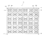
图1是本实用新型混合式电池交换装置第一实施例的俯视图;Fig. 1 is a top view of the first embodiment of the hybrid battery exchange device of the present invention;
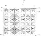
图2是本实用新型混合式电池交换装置第一实施例的主视图;Fig. 2 is the front view of the first embodiment of the hybrid battery exchange device of the present invention;
图3是图1所示的第一容置槽组的主视图;Fig. 3 is a front view of the first accommodation tank group shown in Fig. 1;
图4是图1所示的第二容置槽组的主视图;Fig. 4 is the front view of the second accommodation tank group shown in Fig. 1;
图5是本实用新型混合式电池交换装置的第二实施例图;Fig. 5 is a second embodiment diagram of the hybrid battery exchange device of the present invention;
图6是图5所示的俯视图,显示该电池移动插拔手臂向左或向右抓取或放置充电电池的状态Fig. 6 is a top view shown in Fig. 5, showing the state where the battery moving arm grabs or places the rechargeable battery to the left or right
图7是本实用新型混合式电池交换装置的较佳应用例图。Fig. 7 is a diagram of a preferred application example of the hybrid battery exchange device of the present invention.
图中标号说明:Explanation of symbols in the figure:
100 混合式电池交换装置 10 电池容置列模块100 hybrid
11 第一容置槽组 111 第一连接部11 The first
112 第二连接部 113 电池容置槽112
114 充电座 12 第二容置槽组114 Charging stand 12 Second storage slot group
121 第一连接部 122 第二连接部121 The first connecting
123 电池容置槽 20 轨道123
30 电池移动插拔手臂 31 导轨30 battery
32 导轨驱动器 33 电池抓取器32
200 充电电池 300 补充车辆200
310 补充月台 320 补充月台310
具体实施方式Detailed ways
请参阅图1、图2、图3及图4所示,为本实用新型的混合式电池交换装置100的第一实施例,该混合式电池交换装置100包括至少一电池容置列模块10,该电池容置列模块10包括若干数个第一容置槽组11及第二容置槽组12,该第一容置槽组11于周缘设有若干第一连接部111及第二连接部112,该第一连接部111及第二连接部112的型式不限,在本实用新型中是以第一连接部111为插梢及第二连接部112为凹槽为例,其它等效对应的连接结构,当不脱本实用新型的范畴,各第一容置槽组11之间,通过该第一连接部111与第二连接部112对应连结,使第一容置槽组11间可作如纵向的堆栈组合(如图2所示),各第一容置槽组11内设有若干电池容置槽113,该电池容置槽113内至少设有一充电座114,以供至少一充电电池200容置于该电池容置槽113内进行充电操作。Please refer to Fig. 1, Fig. 2, Fig. 3 and Fig. 4, which are the first embodiment of the hybrid
该第二容置槽组12于周缘设有若干第一连接部121及第二连接部122,该第一连接部121及第二连接部122的型式不限,在本实用新型中是以第一连接部121为插梢及第二连接部122为凹槽为例,其它等效对应的连接结构,当不脱本实用新型的范畴,各第二容置槽组12之间,通过该第一连接部121与第二连接部122对应连结,使第一容置槽组12间可作如纵向的堆栈组合(如图2所示),以及,该第一容置槽组11与第二容置槽组12之间,亦可通过该第一连接部111与第二连接部122之间的对应组合,而作如纵向的堆栈组合(如图2所示),各第二容置槽组12内设有若干电池容置槽123,各电池容置槽113内可供至少一充电电池200容置。The second
上述的第一容置槽组11与第一容置槽组11之间的组合或第二容置槽组12与第二容置槽组12之间的组合,或者第一容置槽组11与第二容置槽组12之间的组合,并不限于上述的纵向堆栈组合型态。The combination of the above-mentioned first
至少一对轨道20,设于该电池容置列模块10一侧上、下端,在本实用新型中是列举设置于两相邻的电池容置列模块10之间上、下端。At least one pair of
至少一电池移动插拔手臂30,设于两轨道20之间,可沿该两轨道20的轨迹,移动于两电池容置列模块10之间的各第一容置槽组11或第二容置槽组12之间,借由该电池移动插拔手臂30对各第一容置槽组11的各电池容置槽113内的充电电池200或第二容置槽组12的各电池容置槽123内的各充电电池200进行移出或储放的交换操作。At least one battery moving plug-in
上述的轨道20与电池移动插拔手臂30间的结构,并不以图1至图4所示为限,举凡是其它等效的三维空间移动轨道与机械手臂结构,当不脱本实用新型的范畴。The above-mentioned structure between the
请再配合图5及图6所示,为本实用新型的混合式电池交换装置100的第二实施例,其中,显示该一对轨道20分别直竖设置于两电池容置列模块10间的前、后方,该电池移动插拔手臂30包括至少一导轨31、至少一导轨驱动器32及至少一电池抓取器33,其中,该导轨31连结于两轨道20间,该导轨驱动器32设于两电池容置列模块10间的前或后方,以驱动该导轨31沿该轨道20的轨迹进行上、下垂直移动(如图5中箭头方向所示),该电池抓取器33结合于该导轨31上,使该电池抓取器33沿该导轨31轨迹进行前、后轴向移动,且该电池抓取器33并向左或右(如图6中的箭头方向所示),朝两侧的电池容置列模块10中的各第一容置槽组11的电池容置槽113或第二容置槽组12的各电池容置槽123内抓取充满电量的充电电池200或将交换的电量耗尽的充电电池200送入电池容置列模块10中的各第一容置槽组11的电池容置槽113或第二容置槽组12的各电池容置槽123内容置,以达成如同上述第一实施例所述的三维空间电池交换的功效。Please cooperate with Fig. 5 and Fig. 6, which is the second embodiment of the hybrid
请再配合图7所示,为本实用新型的混合式电池交换装置100的较佳应用例,其中,显示当需快速补充大量充电电池200时,则由一补充车辆300载着数个第二容置槽组12于各电池容置列模块10外侧进行补充,在本实用新型中是列举于两电池容置列模块10外侧分别设置一补充月台310及320进行作业,各第二容置槽组12内的各电池容置槽113中皆容置充满电量的充电电池200。Please cooperate with that shown in Figure 7, which is a preferred application example of the hybrid
借由上述的第一容置槽组11与第一容置槽组11之间,或第二容置槽组12与第二容置槽组12之间,或者第一容置槽组11与第二容置槽组12之间,均可通过该第一连接部111、121及第二连接部112、122间的对应连结结构,而将原先于两电池容置列模块10内的各个已交换充电电池200数量殆尽的第二容置槽组12吊离或拉离电池容置列模块10至该补充月台310或320,而直接将该补充车辆300中各新的第二容置槽组12吊入组合连结至该电池容置列模块10的第一容置槽组11或第二容置槽组12的上,上述在补充月台310或320中的旧的第二容置槽组12则再吊入补充车辆300中,借此操作可快速大量补充充满电量的充电电池200,以因应原先各电池容置列模块10中充电电池200数量无法因应大量交换的状态,或该第一容置槽组11中的各充电电池200充电时间冗长无法瞬间因应大量充电电池200交换的状态,。Between the above-mentioned first
以上所述,仅是本实用新型的较佳实施例而已,并非对本实用新型作任何形式上的限制,凡是依据本实用新型的技术实质对以上实施例所作的任何简单修改、等同变化与修饰,均仍属于本实用新型技术方案的范围内。The above is only a preferred embodiment of the utility model, and does not limit the utility model in any form. Any simple modification, equivalent change and modification made to the above embodiments according to the technical essence of the utility model, All still belong to within the scope of the technical solution of the utility model.
Claims (6)
Priority Applications (1)
| Application Number | Priority Date | Filing Date | Title |
|---|---|---|---|
| CN2010201147903U CN201655863U (en) | 2010-02-21 | 2010-02-21 | Hybrid battery exchange device |
Applications Claiming Priority (1)
| Application Number | Priority Date | Filing Date | Title |
|---|---|---|---|
| CN2010201147903U CN201655863U (en) | 2010-02-21 | 2010-02-21 | Hybrid battery exchange device |
Publications (1)
| Publication Number | Publication Date |
|---|---|
| CN201655863U true CN201655863U (en) | 2010-11-24 |
Family
ID=43121106
Family Applications (1)
| Application Number | Title | Priority Date | Filing Date |
|---|---|---|---|
| CN2010201147903U Expired - Fee Related CN201655863U (en) | 2010-02-21 | 2010-02-21 | Hybrid battery exchange device |
Country Status (1)
| Country | Link |
|---|---|
| CN (1) | CN201655863U (en) |
Cited By (4)
| Publication number | Priority date | Publication date | Assignee | Title |
|---|---|---|---|---|
| CN103762629A (en) * | 2013-12-27 | 2014-04-30 | 顾连芳 | Device of battery interchanger |
| CN103777564A (en) * | 2013-12-27 | 2014-05-07 | 顾连芳 | Voice activated battery switch device |
| CN108349394A (en) * | 2015-11-04 | 2018-07-31 | 江森自控科技公司 | Hybrid battery control system architecture design system and method |
| CN109795301A (en) * | 2019-01-02 | 2019-05-24 | 北京汽车股份有限公司 | Batteries of electric automobile packet, electric car and electrical changing station |
-
2010
- 2010-02-21 CN CN2010201147903U patent/CN201655863U/en not_active Expired - Fee Related
Cited By (4)
| Publication number | Priority date | Publication date | Assignee | Title |
|---|---|---|---|---|
| CN103762629A (en) * | 2013-12-27 | 2014-04-30 | 顾连芳 | Device of battery interchanger |
| CN103777564A (en) * | 2013-12-27 | 2014-05-07 | 顾连芳 | Voice activated battery switch device |
| CN108349394A (en) * | 2015-11-04 | 2018-07-31 | 江森自控科技公司 | Hybrid battery control system architecture design system and method |
| CN109795301A (en) * | 2019-01-02 | 2019-05-24 | 北京汽车股份有限公司 | Batteries of electric automobile packet, electric car and electrical changing station |
Similar Documents
| Publication | Publication Date | Title |
|---|---|---|
| CN207955601U (en) | Charging and swapping station | |
| CN102180143B (en) | Battery replacing method, battery replacing system and battery rack of electric vehicle | |
| CN207697714U (en) | Electrical changing station | |
| CN109278722B (en) | Electric automobile shared battery system and power conversion method | |
| CN201655863U (en) | Hybrid battery exchange device | |
| CN108216151A (en) | Battery cabin, new energy automobile battery replacement station and battery storage and transportation method | |
| TW201936422A (en) | Battery storage rack and battery replacing station for new-energy automobiles | |
| CN108177635A (en) | Charging and battery-replacing station | |
| CN201918754U (en) | Parallel charging device for multiple power batteries | |
| CN110316162A (en) | A kind of quick plug-in charging storehouse and electrical changing station | |
| CN213501923U (en) | a power station | |
| CN112404942A (en) | Battery cell shell entering device and method | |
| CN115285078A (en) | Power conversion station | |
| CN210150219U (en) | Battery connection device and battery transfer unit | |
| CN218661396U (en) | Small-size automatic power station that trades that fills of electric automobile | |
| CN212219962U (en) | Multi-mode power switching station | |
| CN201590461U (en) | Fixed-point battery exchange device | |
| WO2020082841A1 (en) | Electric car battery sharing system and battery swapping method | |
| CN212784805U (en) | Quick charging device for automobile battery | |
| CN115071643A (en) | Power exchange method and mobile power exchange station | |
| CN208112271U (en) | Battery charging units, battery storage racks and battery operating platforms | |
| CN113212236A (en) | Charging bin and battery replacing station | |
| CN217804393U (en) | Modular trade electric installation and trade power station | |
| CN218112599U (en) | Battery compartment | |
| CN220429923U (en) | Charging pile track device with track change mechanism |
Legal Events
| Date | Code | Title | Description |
|---|---|---|---|
| C14 | Grant of patent or utility model | ||
| GR01 | Patent grant | ||
| C17 | Cessation of patent right | ||
| CF01 | Termination of patent right due to non-payment of annual fee |
Granted publication date: 20101124 Termination date: 20140221 |