CN201714411U - Solid packed hydraulic support for working face - Google Patents
Solid packed hydraulic support for working face Download PDFInfo
- Publication number
- CN201714411U CN201714411U CN2010201400422U CN201020140042U CN201714411U CN 201714411 U CN201714411 U CN 201714411U CN 2010201400422 U CN2010201400422 U CN 2010201400422U CN 201020140042 U CN201020140042 U CN 201020140042U CN 201714411 U CN201714411 U CN 201714411U
- Authority
- CN
- China
- Prior art keywords
- hinged
- jack
- compacting
- back timber
- pedestal
- Prior art date
- Legal status (The legal status is an assumption and is not a legal conclusion. Google has not performed a legal analysis and makes no representation as to the accuracy of the status listed.)
- Expired - Fee Related
Links
- 239000007787 solid Substances 0.000 title claims abstract description 17
- NJPPVKZQTLUDBO-UHFFFAOYSA-N novaluron Chemical compound C1=C(Cl)C(OC(F)(F)C(OC(F)(F)F)F)=CC=C1NC(=O)NC(=O)C1=C(F)C=CC=C1F NJPPVKZQTLUDBO-UHFFFAOYSA-N 0.000 claims description 51
- 230000002787 reinforcement Effects 0.000 claims description 20
- 230000001105 regulatory effect Effects 0.000 claims description 7
- 238000009434 installation Methods 0.000 claims 1
- 239000003245 coal Substances 0.000 abstract description 13
- 238000012856 packing Methods 0.000 abstract description 3
- 238000005056 compaction Methods 0.000 abstract 4
- 230000000694 effects Effects 0.000 description 6
- 238000005065 mining Methods 0.000 description 6
- 238000010276 construction Methods 0.000 description 5
- 238000005516 engineering process Methods 0.000 description 3
- 238000007599 discharging Methods 0.000 description 2
- XLYOFNOQVPJJNP-UHFFFAOYSA-N water Substances O XLYOFNOQVPJJNP-UHFFFAOYSA-N 0.000 description 2
- 230000009286 beneficial effect Effects 0.000 description 1
- 239000000945 filler Substances 0.000 description 1
- 239000010881 fly ash Substances 0.000 description 1
- 238000004519 manufacturing process Methods 0.000 description 1
- 230000035800 maturation Effects 0.000 description 1
- 239000000203 mixture Substances 0.000 description 1
- 239000010813 municipal solid waste Substances 0.000 description 1
- 210000003205 muscle Anatomy 0.000 description 1
- 239000002994 raw material Substances 0.000 description 1
- 238000011084 recovery Methods 0.000 description 1
- 239000002910 solid waste Substances 0.000 description 1
- 239000000725 suspension Substances 0.000 description 1
- 239000002699 waste material Substances 0.000 description 1
Images
Landscapes
- Working Measures On Existing Buildindgs (AREA)
Abstract
The utility model provides a solid packed hydraulic support for a working face, wherein, the upper parts of a front upright post and a rear upright post of the solid packed hydraulic support are respectively hinged with a front top beam and a rear top beam, and the lower ends of the front upright post and the rear upright post are connected with a base; the upper end of a four-bar mechanism is connected with a hinge point of the front top beam and the rear top beam, and the lower end of the four-bar mechanism is connected with the base; the rear part of the front top beam and the front end of the rear top beam are connected with a lifting jack; a backward shift lifting jack and a suspended beam are installed on the rear top beam; a rear chute is formed at the lower part of the suspended beam; a hinged seat is installed at the rear part of the base; and a lower compaction mechanism and an upper compaction mechanism are sequentially installed at the upper front part of the hinged seat. External packing falls to the rear part of the hydraulic support through the rear chute, and then is tamped by the upper compaction mechanism and the lower compaction mechanism and endowed with the function of supporting a top plate, so that mined out space can be filled; in addition, the solid packed hydraulic support with compact design structure can be applied to exploitation for the working faces of various coal beds.
Description
Technical field
The utility model relates to the support apparatus that a kind of colliery underground mining work plane uses, and is specially adapted to the solid filling hydraulic support that mine " three times " (under the building, under the railway, under the water body) is pressed the coal work plane.
Background technology
Rich coal resources in China, the fully-mechanized mining equipment maturation, coal winning technology is gradually improved, quickening along with coal in China exploitation paces, a lot of mines are faced with the resource exhaustion problem, and some contain the coal seam that is considered to be unsuitable for exploitation below building, road and water body, also more and more are subjected to more concern.China presses coal by adopting multiple technologies measures such as traditional band exploitation, resettlement village, filling mining to solve " three times ", improves coal mining rate.But the village resettlement has caused the mass breaking subsidence area, causes serious ecology and cultural environment to destroy.Simultaneously, be accompanied by the discharging of a large amount of solid waste spoils in the coal production, the discharging spoil attitude environment of looking unfamiliar over the ground does great damage.We can turn waste into wealth these spoils, carry out filling with it as raw material and press the coal problem with better solution " three times ".The back timber of existing filling support is integral top beam mostly, and at the hinged tail boom in back timber rear portion, and the effect by the tail boom jack realizes the support to goaf, hydraulic support rear portion, and its shortcoming is the support force at rear portion smaller.
Summary of the invention
The purpose of this utility model has been to provide a kind of supporting that can play the underground mining work plane can realize the goaf is carried out the hydraulic support of packing job again, can prevent the goaf land subsidence, improve the utilization rate and the rate of recovery of coal resources, effectively solve the mining problem that " three times " press coal, realized the green exploitation and the ecological exploitation of harmony between man and nature.
For achieving the above object, the technical solution adopted in the utility model is: a kind of work plane solid filling hydraulic support, comprise preceding back timber, back back timber, base, quadric chain, front column and rear column, it is characterized in that the hinged respectively preceding back timber 6 in upper end, the back back timber 10 of front column 7, rear column 11, its lower end and base 25 link; The upper end of quadric chain connects with the pin joint of preceding back timber 6, back back timber 10, and its lower end and base 25 link; An end that connects hinged jack 8 at the rear portion of preceding back timber 6, the other end of hinged jack 8 is hinged with the front end of back back timber 10; Install at the postmedian of back back timber 10 and to draw the back to slip jack 12, draw the back to slip the other end of jack 12 and be connected with drop in beam 13, the below of drop in beam 13 is connected rear portion chute 15 by link with round-link chain; The rear portion of base 25 be provided with hinged seat 24, on reinforcement mechanism and following reinforcement mechanism.
Described quadric chain comprises front rod 27, back link 26, goes up connecting rod 9 and base 25, and an end of hinged front rod 27, back link 26 on base 25, the other end of front rod 27, back link 26 are hinged with the bottom of last connecting rod 9 respectively; Last connecting rod is a y-type structure, and two upper end is hinged with preceding back timber 6 and back back timber 10 respectively; Quadric chain is positioned in the middle of front column 7 and the rear column 11, and the last connecting rod 9 of described quadric chain, front rod 27, back link 26 are body structure.
The rear portion of described base 25 connects hinged seat 24, reinforcement mechanism and last reinforcement mechanism under the front upper place of hinged seat 24 connects successively.
Described down reinforcement mechanism comprise compacting down regulate jack 23, down compacting jack 22, down tamp pedestal 20 and down compacting smash cash mechanism 21, an end and hinged seat 24 that jack 23 is regulated in following compacting are hinged, the other end is with following to tamp pedestal 20 hinged; One end of following compacting jack 22 connects with the front end of tamping pedestal 20 down, and it is hinged that cash mechanism 21 is smash in the other end and following compacting; Under tamp pedestal 20 and down compacting smash cash mechanism 21 and be respectively body structure, following compacting is smash cash mechanism 21 and is installed to down the inner chamber of tamping pedestal 20 from the rear end cover of tamping pedestal 20 down.
Described go up reinforcement mechanism comprise compacting regulate jack 19, on tamp jack 17, on tamp pedestal 16 and go up compacting and smash cash mechanism 18, a last end and the hinged seat 24 of tamping adjusting jack 19 is hinged, the other end and last compacting pedestal 16 are hinged; One end of last compacting jack 17 connects with the front end of last compacting pedestal 16, and it is hinged that cash mechanism 18 is smash in the other end and last compacting; Last compacting pedestal 16 and last compacting are smash cash mechanism 18 and are respectively body structure, and cash mechanism 18 installs to compacting pedestal 16 from the rear end cover of last compacting pedestal 16 inner chamber is smash in last compacting.
Described front column 7 and rear column 11 are two, and symmetry is fixed on the both sides of base 25 and preceding back timber 6, back back timber 10 respectively.
Install at back back timber 10 postmedians and to draw the back to slip jack 12, draw the back to slip the other end of jack 12 and be connected with drop in beam 13, the below of drop in beam 13 is connected rear portion chute 15 by link with round-link chain.
The front end of back timber 6 is provided with extensible canopy 2, extensible canopy jack 5, preceding supporting plate 4, face guard 1 and wall supporting jack 3 before described; One end and the preceding back timber 6 of extensible canopy jack 5 are hinged, and its other end and extensible canopy 2 are hinged; Supporting plate 4 before the front end of extensible canopy 2 is hinged, preceding supporting plate 4 inserts in the slideway of preceding back timber 6, an end of the hinged face guard jack 3 in the rear portion of preceding supporting plate 4, the rear portion of the other end of wall supporting jack 3 and face guard 1 is hinged.
Before back timber 6, back back timber 10 and base 25 be respectively arranged with needling with the junction at front column 7, rear column 11 two ends respectively.
The beneficial effects of the utility model are: the utility model is except being provided with suspension devices such as preceding back timber, back back timber, base, column and quadric chain, and also the front end at preceding back timber is provided with extensible canopy and face guard; Install at back timber rear portion, back and to draw the back to slip jack, draw the back to slip the other end of jack and be connected with drop in beam, the drop in beam below uses link to be connected the rear portion chute with round-link chain; Hinged seat is installed in rear end at base, and the front upper place of hinged seat is installed down reinforcement mechanism and last reinforcement mechanism successively.By the rear portion transportation charges such as outside spoil, flyash, household garbage are transported into the goaf, it are tamped, realize filling the goaf through last reinforcement mechanism and following reinforcement mechanism.
Description of drawings
The utility model has following view:
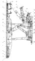
Fig. 1 is a structural representation of the present utility model.
The specific embodiment
Embodiment 1:
A kind of work plane solid filling hydraulic support, back timber 6, back back timber 10, base 25, front column 7, rear column 11 and quadric chain before comprising, preceding back timber 6 and back back timber 10 all adopt monolithic high strength casing welded construction and are provided with side guard board; The upper end of front column 7 and rear column 11 is hinged with preceding back timber 6 and back back timber 10 respectively, and the lower end of front column 7 and rear column 11 is hinged with base 25 respectively; Quadric chain by front rod 27, back link 26, go up connecting rod 9 and base 25 is formed, by an end of hinged front rod 27, back link 26 on base 25, the other end of front rod 27, back link 26 is hinged with the bottom of last connecting rod 9 respectively; Last connecting rod 9 is a y-type structure, and two upper end is hinged with preceding back timber 6 and back back timber 10 respectively; Back back timber 10 front portions are high strength casing welded construction, postmedian is provided with drop in beam 13 and draws back slide jack 12, draw an end of back slide jack 12 to be hinged with back back timber 10, draw the other end of back slide jack 12 to be connected with drop in beam 13, below drop in beam 13, be connected rear portion chute 15 with round-link chain by link, rear portion chute 15 is set to open-celled structure, jack is installed with the closing and opening of control chute perforate, to guarantee the supply of filler at the side of rear portion chute 15; At the hinged back, rear portion of back back timber 10 lengthening beam 14, to realize support to the hydraulic support rear portion.Described drop in beam 13 adopts plate muscle welded construction, drop in beam 13 flexibly connects with back back timber 10 by the chute that is arranged on back timber 10 bottom surfaces, back, after the packing job at a place was finished, drop in beam 13 can slide into new setting in the chute of back back timber 10 under the effect of drawing back slide jack 12.The rear portion of described base 25 also is provided with hinged seat 24, reinforcement mechanism and last reinforcement mechanism under installing successively in the front upper place of hinged seat 24.
In the present embodiment, described down reinforcement mechanism comprise compacting down regulate jack 23, down compacting jack 22, down tamp pedestal 20 and down compacting smash cash mechanism 21 and form, an end and hinged seat 24 that jack 23 is regulated in following compacting are hinged, the other end is with down compacting pedestal 20 is hinged, regulates jack 23 actions by compacting down and make that compacting pedestal 20 can be swung around pin joint down in certain angle; One end of following compacting jack 22 connects with the front end of tamping pedestal 20 down, and it is hinged that cash mechanism 21 is smash in the other end and following compacting; Under tamp pedestal 20 and down compacting smash cash mechanism 21 and be respectively body structure, cash mechanism 21 installs to down compacting pedestal 20 from the rear end cover of tamping pedestal 20 down inner chamber is smash in following compacting, can make down compacting smash cash mechanism 21 by operating down compacting jack 22 along descending compacting pedestal 20 inner chambers to stretch out and withdrawing, cooperate compacting down to regulate jack 23, can realize compacting goaf filling thing bottom.
In the present embodiment, described go up reinforcement mechanism comprise compacting regulate jack 19, on tamp jack 17, on tamp pedestal 16 and go up compacting and smash cash mechanism 18 compositions, an end and hinged seat 24 that jack 19 is regulated in last compacting are hinged, the other end and last compacting pedestal 16 are hinged, regulate jack 19 actions by last compacting and make that going up compacting pedestal 16 can swing around pin joint in certain angle; One end of last compacting jack 17 connects with the front end of last compacting pedestal 16, and it is hinged that cash mechanism 18 is smash in the other end and last compacting; Last compacting pedestal 16 and last compacting are smash cash mechanism 18 and are respectively body structure, cash mechanism 18 installs to compacting pedestal 16 from the rear end cover of last compacting pedestal 16 inner chamber is smash in last compacting, can make to tamp and smash cash mechanism 18 and stretch out and withdraw by operating compacting jack 17 along last compacting pedestal 16 inner chambers, jack 19 is regulated in compacting in the cooperation, can realize the compacting to goaf filling thing top.
In the present embodiment, described front column 7 and rear column 11 are two, symmetry is positioned at base 25 and preceding back timber 6 respectively, the both sides of back back timber 10, hydraulic support front column and integral top beam of rear column support have in the past been changed, by hinged tail boom in integral top beam rear portion and tail boom jack, support pattern in the goaf, effect lower support hydraulic support rear portion of tail boom jack, integral top beam is designed to disconnected girder construction---preceding back timber 6 and back back timber 10, before back timber 6 and back back timber 10 shared pin joints hinged with the upper end of the last connecting rod of quadric chain, the upper end of rear column 11 directly and after the back timber 10 hinged enabling capabilities that increase the hydraulic support rear portion.The rear end of preceding back timber 6 connects an end of hinged jack 8, the other end of hinged jack 8 is connected with the front end of back back timber 10, by regulating hinged jack 8, keep horizontal arrangement in working order with back timber 6 before satisfying and back back timber 10, realize support to top board; Quadric chain is between front column 7 and rear column 11; Front rod 27, back link 26 are respectively independently high strength casing welded construction, about front rod 27, back link 26 and last connecting rod 9 formed quadric chains are between two row's columns, make the layout that hydraulic support structural member is rationally compact.
In the present embodiment, the front end of described preceding back timber 6 also is provided with extensible canopy 2, extensible canopy jack 5, face guard 1, wall supporting jack 3 and preceding supporting plate 4; The both sides of extensible canopy 2 are set to body structure, the centre is a plank frame, the cabinets cavity that back timber 6 both sides form before being inserted in, and at the fixing end of extensible canopy jack 5 of the front end of extensible canopy 2, the other end of extensible canopy jack 5 is fixed on the preceding back timber 6, by the action of extensible canopy jack 5, extensible canopy 2 is stretched out in the casing of preceding back timber 6 and withdraw; Hinged at the front end of the front center of extensible canopy 2 and preceding supporting plate 4 in addition, preceding supporting plate 4 inserts in the chute of preceding back timber 6, the fixing end of wall supporting jack 3 at the rear portion of preceding supporting plate 4, the other end of wall supporting jack 3 is hinged on the rear end of face guard 1, support face guard 1 by wall supporting jack 3, face guard 1 can play support action at the front end of preceding back timber 6 and can prevent coal wall caving.Described base 25 adopts band gap bridge easy opened high strength casing welded construction, it directly acts on the work plane base plate, the crotch place that opens at base 25 also is provided with push rod 29 and passes jack 28, the front end of push rod 29 is provided with connector and is connected with the transporter of work plane, the rear end of push rod 29 is connected the effect of playing pushing and sliding and moving frame by passing jack 28 under the effect of passing jack 28 with base 25.On the link position at preceding back timber 6, back back timber 10 and base 25 and the two ends up and down of front column 7 and rear column 11, all be respectively arranged with needling, so that hinge connection activity freely.
Claims (9)
1. work plane solid filling hydraulic support, comprise preceding back timber, back back timber, base, quadric chain, front column and rear column, it is characterized in that the hinged respectively preceding back timber (6) in upper end, the back back timber (10) of front column (7), rear column (11), its lower end and base (25) link; The upper end of quadric chain connects with the pin joint of preceding back timber (6), back back timber (10), and its lower end and base (25) link; An end that connects hinged jack (8) at the rear portion of preceding back timber (6), the other end of hinged jack (8) is hinged with the front end of back back timber (10); Install at the postmedian of back back timber (10) and to draw the back to slip jack (12), draw the back to slip the other end of jack (12) and be connected with drop in beam (13), the below of drop in beam (13) is connected rear portion chute (15) by link with round-link chain; Be provided with hinged seat (24) at the rear portion of base (25), go up reinforcement mechanism and following reinforcement mechanism.
2. work plane solid filling hydraulic support according to claim 1, it is characterized in that quadric chain comprises front rod (27), back link (26), goes up connecting rod (9) and base (25), go up an end of hinged front rod (27), back link (26) at base (25), the other end of front rod (27), back link (26) is hinged with the bottom of last connecting rod (9) respectively; Last connecting rod is a y-type structure, and two upper end is hinged with preceding back timber (6) and back back timber (10) respectively; Quadric chain is positioned in the middle of front column (7) and the rear column (11), and the last connecting rod (9) of described quadric chain, front rod (27), back link (26) are body structure.
3. work plane solid filling hydraulic support according to claim 1 is characterized in that the rear portion of described base (25) connects hinged seat (24), connects reinforcement mechanism and last reinforcement mechanism down successively in the front upper place of hinged seat (24).
4. work plane solid filling hydraulic support according to claim 1, it is characterized in that described down reinforcement mechanism comprise compacting down regulate jack (23), down compacting jack (22), tamp pedestal (20) and tamp down and smash cash mechanism (21) down, an end and hinged seat (24) that jack (23) is regulated in following compacting are hinged, and the other end is with compacting pedestal (20) is hinged down; One end of following compacting jack (22) connects with the front end of tamping pedestal (20) down, and it is hinged that cash mechanism (21) is smash in the other end and following compacting; Under tamp pedestal (20) and down compacting smash cash mechanism (21) and be respectively body structure, following compacting is smash cash mechanism (21) and is installed to down the inner chamber of tamping pedestal (20) from the rear end cover of tamping pedestal (20) down.
5. work plane solid filling hydraulic support according to claim 1, it is characterized in that described go up reinforcement mechanism comprise compacting adjusting jack (19), on tamp jack (17), on tamp pedestal (16) and cash mechanism (18) is smash in last compacting, an end and hinged seat (24) that jack (19) is regulated in last compacting are hinged, and the other end and last compacting pedestal (16) are hinged; One end of last compacting jack (17) connects with the front end of last compacting pedestal (16), and it is hinged that cash mechanism (18) is smash in the other end and last compacting; Last compacting pedestal (16) and last compacting are smash cash mechanism (18) and are respectively body structure, and cash mechanism (18) installs to compacting pedestal (16) from the rear end cover of last compacting pedestal (16) inner chamber is smash in last compacting.
6. work plane solid filling hydraulic support according to claim 1 is characterized in that described front column (7) and rear column (11) are two, and symmetry is fixed on the both sides of base (25) and preceding back timber (6), back back timber (10) respectively.
7. work plane solid filling hydraulic support according to claim 1, it is characterized in that drawing back slide jack (12) in back back timber (10) postmedian installation, draw the other end of back slide jack (12) to be connected with drop in beam (13), the below of drop in beam (13) is connected rear portion chute (15) by link with round-link chain.
8. work plane solid filling hydraulic support according to claim 1 is characterized in that being provided with extensible canopy (2), extensible canopy jack (5), preceding supporting plate (4), face guard (1) and wall supporting jack (3) at the front end of preceding back timber (6); One end of extensible canopy jack (5) and preceding back timber (6) are hinged, and its other end and extensible canopy (2) are hinged; Supporting plate (4) before the front end of extensible canopy (2) is hinged, preceding supporting plate (4) insert in the slideway of preceding back timber (6), an end of the hinged face guard jack in the rear portion of preceding supporting plate (4) (3), and the rear portion of the other end of wall supporting jack (3) and face guard (1) is hinged.
9. work plane solid filling hydraulic support according to claim 1 is characterized in that preceding back timber (6), back back timber (10) and base (25) are respectively arranged with needling with the junction at front column (7), rear column (11) two ends respectively.
Priority Applications (1)
| Application Number | Priority Date | Filing Date | Title |
|---|---|---|---|
| CN2010201400422U CN201714411U (en) | 2010-03-25 | 2010-03-25 | Solid packed hydraulic support for working face |
Applications Claiming Priority (1)
| Application Number | Priority Date | Filing Date | Title |
|---|---|---|---|
| CN2010201400422U CN201714411U (en) | 2010-03-25 | 2010-03-25 | Solid packed hydraulic support for working face |
Publications (1)
| Publication Number | Publication Date |
|---|---|
| CN201714411U true CN201714411U (en) | 2011-01-19 |
Family
ID=43460409
Family Applications (1)
| Application Number | Title | Priority Date | Filing Date |
|---|---|---|---|
| CN2010201400422U Expired - Fee Related CN201714411U (en) | 2010-03-25 | 2010-03-25 | Solid packed hydraulic support for working face |
Country Status (1)
| Country | Link |
|---|---|
| CN (1) | CN201714411U (en) |
Cited By (8)
| Publication number | Priority date | Publication date | Assignee | Title |
|---|---|---|---|---|
| CN102251790A (en) * | 2011-08-05 | 2011-11-23 | 中国矿业大学 | Mining and filling integrated hydraulic support enabling double top beams to be coaxially hinged with four connecting rods |
| CN102808637A (en) * | 2011-05-31 | 2012-12-05 | 高九华 | Reverse four-connecting-rod filling hydraulic support with compaction function |
| WO2013131318A1 (en) * | 2012-03-07 | 2013-09-12 | 中煤北京煤矿机械有限责任公司 | Two-prop shield hydraulic support for large centre to centre distance and ultra-high working resistance in medium-thickness coal seams |
| WO2014090109A1 (en) * | 2012-12-10 | 2014-06-19 | 中国矿业大学 | Large mining height filling coal mining hydraulic support with coaxially hinged front and rear top beams |
| CN109026090A (en) * | 2018-08-24 | 2018-12-18 | 江苏省交通技师学院 | A kind of concave-convex curved surface filling bracket reinforcement mechanism |
| CN109989787A (en) * | 2019-05-09 | 2019-07-09 | 陕西长武亭南煤业有限责任公司 | A combined tamping mechanism for coal mine gangue filling |
| CN110966039A (en) * | 2019-11-20 | 2020-04-07 | 淮南创大实业有限责任公司 | A gangue filling and tamping device |
| CN110985117A (en) * | 2019-11-20 | 2020-04-10 | 淮南创大实业有限责任公司 | Waste filling tamping device |
-
2010
- 2010-03-25 CN CN2010201400422U patent/CN201714411U/en not_active Expired - Fee Related
Cited By (11)
| Publication number | Priority date | Publication date | Assignee | Title |
|---|---|---|---|---|
| CN102808637A (en) * | 2011-05-31 | 2012-12-05 | 高九华 | Reverse four-connecting-rod filling hydraulic support with compaction function |
| CN102251790A (en) * | 2011-08-05 | 2011-11-23 | 中国矿业大学 | Mining and filling integrated hydraulic support enabling double top beams to be coaxially hinged with four connecting rods |
| WO2013131318A1 (en) * | 2012-03-07 | 2013-09-12 | 中煤北京煤矿机械有限责任公司 | Two-prop shield hydraulic support for large centre to centre distance and ultra-high working resistance in medium-thickness coal seams |
| WO2014090109A1 (en) * | 2012-12-10 | 2014-06-19 | 中国矿业大学 | Large mining height filling coal mining hydraulic support with coaxially hinged front and rear top beams |
| CN109026090A (en) * | 2018-08-24 | 2018-12-18 | 江苏省交通技师学院 | A kind of concave-convex curved surface filling bracket reinforcement mechanism |
| CN109989787A (en) * | 2019-05-09 | 2019-07-09 | 陕西长武亭南煤业有限责任公司 | A combined tamping mechanism for coal mine gangue filling |
| CN109989787B (en) * | 2019-05-09 | 2024-01-19 | 陕西长武亭南煤业有限责任公司 | Coal mine gangue filling combined tamping mechanism |
| CN110966039A (en) * | 2019-11-20 | 2020-04-07 | 淮南创大实业有限责任公司 | A gangue filling and tamping device |
| CN110985117A (en) * | 2019-11-20 | 2020-04-10 | 淮南创大实业有限责任公司 | Waste filling tamping device |
| CN110985117B (en) * | 2019-11-20 | 2021-03-09 | 淮南创大实业有限责任公司 | Waste filling tamping device |
| CN110966039B (en) * | 2019-11-20 | 2021-03-09 | 淮南创大实业有限责任公司 | A gangue filling and tamping device |
Similar Documents
| Publication | Publication Date | Title |
|---|---|---|
| CN201714411U (en) | Solid packed hydraulic support for working face | |
| CN201714412U (en) | Hydraulic support for non-solid-filled working face | |
| CN101988388A (en) | Filling and supporting hydraulic support with compaction mechanism | |
| CN101725365B (en) | Hexastyle supporting type coal mining and filling hydraulic bracket | |
| CN202628177U (en) | Gangue-coal ash two-column shield-type hydraulic filling support | |
| CN102094664B (en) | Hydraulic bracket for end of comprehensive mechanized filling coal face | |
| CN105065049A (en) | Hydraulic support for high-water cut and fill mining | |
| CN102168572B (en) | gangue filling support bracket | |
| CN103397905A (en) | System and method for achieving natural striding, falling and filling of coal beds, flexible roadway protection and complete gob-side entry retaining | |
| CN103410545B (en) | The hydraulic support of Sub-Level Caving and packing job can be realized | |
| CN103306697A (en) | Three-column paste body filling hydraulic bracket for underground thin coal seam and four-step paste body filling process | |
| CN102979545A (en) | Large-mining-height front and rear top beam coaxial articulated fill coal mining hydraulic bracket | |
| CN201606089U (en) | Integrated hydraulic support for support and filling | |
| CN201460939U (en) | Filling and timbering hydraulic support with a tamping mechanism | |
| CN102926781B (en) | The anti-linkage support apparatus of a kind of gob side entry retaining | |
| CN102168567A (en) | Filling supporting partition board bracket | |
| CN201982127U (en) | Multistage plug-in connecting rod type filling hydraulic support | |
| CN201810325U (en) | Solid filling end bracket | |
| CN201835851U (en) | Coal face end timbering, filling and transshipping system | |
| CN201606097U (en) | Waste rock filling supporting bracket | |
| CN201554482U (en) | A six-column supporting coal mining filling hydraulic support | |
| CN102661160A (en) | Two-pillar hidden type filled hydraulic support | |
| CN201306180Y (en) | Filling and supporting hydraulic support | |
| CN102251790A (en) | Mining and filling integrated hydraulic support enabling double top beams to be coaxially hinged with four connecting rods | |
| CN202012363U (en) | Waste filling mining hydraulic bracket |
Legal Events
| Date | Code | Title | Description |
|---|---|---|---|
| C14 | Grant of patent or utility model | ||
| GR01 | Patent grant | ||
| C17 | Cessation of patent right | ||
| CF01 | Termination of patent right due to non-payment of annual fee |
Granted publication date: 20110119 Termination date: 20140325 |