CN201717838U - Piezoelectric vibrator - Google Patents
Piezoelectric vibrator Download PDFInfo
- Publication number
- CN201717838U CN201717838U CN201020156825XU CN201020156825U CN201717838U CN 201717838 U CN201717838 U CN 201717838U CN 201020156825X U CN201020156825X U CN 201020156825XU CN 201020156825 U CN201020156825 U CN 201020156825U CN 201717838 U CN201717838 U CN 201717838U
- Authority
- CN
- China
- Prior art keywords
- substrate
- piezoelectric vibrator
- base
- piezoelectric
- vibrator according
- Prior art date
- Legal status (The legal status is an assumption and is not a legal conclusion. Google has not performed a legal analysis and makes no representation as to the accuracy of the status listed.)
- Expired - Lifetime
Links
Images
Landscapes
- Piezo-Electric Or Mechanical Vibrators, Or Delay Or Filter Circuits (AREA)
Abstract
本实用新型提供一种用于电子元器件的压电振动器,包括基板及设于所述基板的压电片,还包括收容所述基板及所述压电片的底座,所述底座设有卡扣部,所述基板对应所述卡扣部设有凹口,所述卡扣部紧压所述基板于所述底座。本实用新型的压电振动器具有安装分便、稳定性好及结构紧凑等优点。

The utility model provides a piezoelectric vibrator for electronic components, which comprises a substrate and a piezoelectric sheet arranged on the substrate, and also includes a base for accommodating the substrate and the piezoelectric sheet, and the base is provided with A buckle part, the substrate is provided with a notch corresponding to the buckle part, and the buckle part presses the base plate against the base. The piezoelectric vibrator of the utility model has the advantages of convenient installation, good stability, compact structure and the like.
Description
技术领域technical field
本实用新型涉及一种压电振动器,尤其涉及一种安装方便的压电振动器。The utility model relates to a piezoelectric vibrator, in particular to a piezoelectric vibrator which is easy to install.
背景技术Background technique
在手机等便携通信设备快速发展的过程中,对安装在其中的电声器件的要求越来越高。During the rapid development of portable communication devices such as mobile phones, the requirements for electroacoustic devices installed in them are getting higher and higher.
为了达到节省空间、提升品质的目的,电子元器件逐步向超小超薄方向发展,由此,作为来电提示、触控反馈等效果的最主要实现者,压电振动器的发展也相应加快。In order to achieve the purpose of saving space and improving quality, electronic components are gradually developing in the direction of ultra-small and ultra-thin. Therefore, as the main implementer of effects such as call notification and touch feedback, the development of piezoelectric vibrators has also accelerated accordingly.
压电振动器的结构包括基板及贴设于基板的压电片,所述基板与所述压电片共同组成压电振动器的压电振子。所述压电振动器通常需要通过支撑件将其承载并安装固定到电子元器件上。The structure of the piezoelectric vibrator includes a substrate and a piezoelectric sheet attached to the substrate. The substrate and the piezoelectric sheet together form a piezoelectric vibrator of the piezoelectric vibrator. The piezoelectric vibrator usually needs to be carried and fixed to the electronic components through a support.
然而,通常情况下,由于所述支撑件与所述压电振动器组合之后,其整体结构不紧凑,一方面不利于所述压电振动器稳固于所述电子元器件;另一方面会占用太多空间,随着电子元器件逐步变得超小超薄,上述问题就显得更加突出。However, usually, since the support member is combined with the piezoelectric vibrator, its overall structure is not compact, on the one hand, it is not conducive to the stability of the piezoelectric vibrator on the electronic components; on the other hand, it will occupy Too much space, as electronic components gradually become ultra-small and ultra-thin, the above problems become more prominent.
由此看来,设计一种能与电子元器件便利安装的压电振动器实为必要。From this point of view, it is necessary to design a piezoelectric vibrator that can be conveniently installed with electronic components.
实用新型内容Utility model content
针对现有压电振动器不易安装的问题,本实用新型提供一种安装便利的压电振动器。Aiming at the problem that the existing piezoelectric vibrator is difficult to install, the utility model provides a piezoelectric vibrator with convenient installation.
一种用于电子元器件的压电振动器,包括基板及设于所述基板的压电片,还包括收容所述基板及所述压电片的底座,所述底座设有卡扣部,所述基板对应所述卡扣部设有凹口,所述卡扣部紧压所述基板于所述底座。A piezoelectric vibrator for electronic components, including a substrate and a piezoelectric sheet disposed on the substrate, and a base for accommodating the substrate and the piezoelectric sheet, the base is provided with a buckle portion, The substrate is provided with a notch corresponding to the buckle portion, and the buckle portion presses the substrate tightly against the base.
作为上述压电振动器的进一步改进,所述卡扣部与所述凹口相吻合。As a further improvement of the above-mentioned piezoelectric vibrator, the buckle part coincides with the notch.
作为上述压电振动器的进一步改进,所述底座设有收容空间,所述收容空间内设置有一台阶,所述台阶将所述基板与压电片分开设置。As a further improvement of the above piezoelectric vibrator, the base is provided with a receiving space, and a step is arranged in the receiving space, and the step separates the substrate and the piezoelectric sheet.
作为上述压电振动器的进一步改进,所述底座包括底壁及侧壁,所述底壁内侧表面配合所述侧壁内侧表面围成所述收容空间。As a further improvement of the above piezoelectric vibrator, the base includes a bottom wall and a side wall, and the inner surface of the bottom wall cooperates with the inner surface of the side wall to enclose the accommodation space.
作为上述压电振动器的进一步改进,所述凹口沿所述基板的周缘设置。As a further improvement of the above piezoelectric vibrator, the notch is arranged along the periphery of the substrate.
作为上述压电振动器的进一步改进,所述卡扣部沿所述底座边缘向内延伸而成。As a further improvement of the above piezoelectric vibrator, the buckle part is formed by extending inward along the edge of the base.
作为上述压电振动器的进一步改进,所述底座设有卡槽,所述卡槽与所述卡扣部相对设置。As a further improvement of the above-mentioned piezoelectric vibrator, the base is provided with a locking groove, and the locking groove is arranged opposite to the locking portion.
作为上述压电振动器的进一步改进,所述基板设有与所述电子元器件接触的接触部。As a further improvement of the above piezoelectric vibrator, the substrate is provided with a contact portion that is in contact with the electronic component.
本实用新型的所述基板与所述底座通过所述凹口与所述卡扣部的紧密配合固定,不仅安装方便且稳定性好,同时所述压电振动器整体结构紧凑,适应所述电子元器件朝轻薄化发展的需求。The base plate and the base of the utility model are fixed by the close fit between the notch and the buckle part, which not only facilitates installation but also has good stability. The demand for components to be thinner and lighter.
综上所述,本实用新型的压电振动器具有安装分便、稳定性好及结构紧凑等优点。In summary, the piezoelectric vibrator of the present invention has the advantages of convenient installation, good stability and compact structure.
附图说明Description of drawings
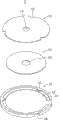
图1是本实用新型的压电振动器的立体分解示意图。FIG. 1 is a three-dimensional exploded schematic diagram of a piezoelectric vibrator of the present invention.
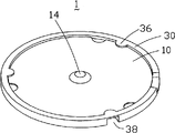
图2是图1中所示压电振动器的立体组合示意图。FIG. 2 is a three-dimensional combined schematic view of the piezoelectric vibrator shown in FIG. 1 .
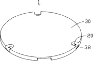
图3是图2中所示压电振动器沿相反方向的立体组合示意图。FIG. 3 is a schematic three-dimensional assembly view of the piezoelectric vibrator shown in FIG. 2 along the opposite direction.
具体实施方式Detailed ways
下面结合附图对本实用新型的压电振动器结构进行说明。The structure of the piezoelectric vibrator of the present invention will be described below in conjunction with the accompanying drawings.
请一并参阅图1至图3,本实用新型的压电振动器1主要用于电子元器件(图未示),如手机或其他消费性电子产品,所述压电振动器1靠近所述电子元器件(图未示)的触摸屏(图未示)设置,以便将所述压电振动器1产生的振动传递到所述电子元器件(图未示)。Please refer to FIGS. 1 to 3 together. The
所述压电振动器1包括基板10、压电片20及底座30。所述压电片20贴设于所述基板10底表面,所述底座30承载所述基板10与所述压电片20并固定所述基板10。所述基板10与所述压电片20共同组成所述压电振动器1的压电振子(未标示)。The
所述基板10呈圆形,其圆周边缘设有三个凹口12,所述凹口12相对于所述基板10的圆心呈正三角设置。本实施方式中,所述凹口12呈半圆形。然,所述凹口12也可是其他形状,如圆弧形或是三角形等,只要所述凹口12面向所述基板10凹进即可。所述基板10顶表面中心处设有一接触部14,所述接触部14为圆形凸起,用来与所述电子元器件的触摸屏接触。所述接触部14也可设为其他形状,如方形等。The
所述压电片20呈圆形,中央设有一圆孔22,以便于导线(图未示)穿过。所述压电片20的外径小于所述基板10的外径。所述压电片20具有逆压电效应,即在外加电场的作用下,发生机械变形。所述压电片20由压电材料制成,压电材料一般包括压电晶体、压电陶瓷及有机高分子压电材料。本实施方式中,所述压电片20是由压电陶瓷材料制成。所述压电片20可以设置为多层结构。The
所述压电片20通过设置于所述基板10的导电电极(图未示)与所述基板10电性连接。所述压电片20均设有金属片(图未示),所述压电片20是通过金属片与外部的电路板(图未示)电性连接。The
所述底座30包括一圆形底壁32及一圆柱状侧壁(未标示),所述圆形底壁内侧表面配合所述圆柱状侧壁内侧表面围成收容空间(未标示)。所述底座30的收容空间内设置有一台阶34。所述台阶34将所述收容空间分割为上下两部分,其中下部分对应收容所述压电片20,上部分对应收容所述基板10。所述底座30沿其周缘设有卡扣部36,所述卡扣部36与所述基板10的凹口12对应设置。所述卡扣部36的形状与所述凹口12相吻合,以便所述卡扣部36与所述凹口12完全咬合,便于将所述基板10放置于所述收容空间内。所述底壁32外表面设有卡槽38,用来与所述电子元器件配合固定,所述卡槽38与卡扣部36分设于所述底座30的两相对表面。本实施方式中,所述卡槽38对应于所述卡扣部36设置。然,可以理解的,所述卡槽38的位置关系不受此限制,也可与所述卡扣部36错开设置。The
所述压电振动器1组装时,所述压电片20收容于所述底座30收容空间的下部分,所述凹口对应于所述卡扣部36并将所述基板10压入所述底座30收容空间的上部分,接着,旋转所述基板10使所述卡扣部36紧压在所述基板10,将所述基板10固定于所述底座30的收容空间内。When the
所述压电振动器1工作时,通过导线接入电信号,所述基板10上的导电电极使所述压电片20产生电场效应,从而使所述压电片20发生逆压电效应,使所述压电振动器1产生振动,振动力通过所述基板10的接触部14传至所述电子元器件的触摸屏。When the
本实用新型中,所述基板10与所述底座30通过所述凹口12与所述卡扣部36之间的紧密配合而固定,不仅安装方便且稳定性好,同时所述压电振动器1整体结构紧凑,适应所述电子元器件朝轻薄化发展的需求。In the present utility model, the
综上所述,本实用新型的所述压电振动器1具有安装分便、稳定性好及结构紧凑等优点。In summary, the
以上仅为本实用新型的优选实施案例而已,并不用于限制本实用新型,对于本领域的技术人员来说,本实用新型可以有各种更改和变化。凡在本实用新型的精神和原则之内,所作的任何修改、等同替换、改进等,均应包含在本实用新型的保护范围之内。The above are only preferred implementation examples of the utility model, and are not intended to limit the utility model. For those skilled in the art, the utility model may have various modifications and changes. Any modification, equivalent replacement, improvement, etc. made within the spirit and principles of the present utility model shall be included in the protection scope of the present utility model.
Claims (8)
Priority Applications (1)
| Application Number | Priority Date | Filing Date | Title |
|---|---|---|---|
| CN201020156825XU CN201717838U (en) | 2010-04-06 | 2010-04-06 | Piezoelectric vibrator |
Applications Claiming Priority (1)
| Application Number | Priority Date | Filing Date | Title |
|---|---|---|---|
| CN201020156825XU CN201717838U (en) | 2010-04-06 | 2010-04-06 | Piezoelectric vibrator |
Publications (1)
| Publication Number | Publication Date |
|---|---|
| CN201717838U true CN201717838U (en) | 2011-01-19 |
Family
ID=43463846
Family Applications (1)
| Application Number | Title | Priority Date | Filing Date |
|---|---|---|---|
| CN201020156825XU Expired - Lifetime CN201717838U (en) | 2010-04-06 | 2010-04-06 | Piezoelectric vibrator |
Country Status (1)
| Country | Link |
|---|---|
| CN (1) | CN201717838U (en) |
Cited By (3)
| Publication number | Priority date | Publication date | Assignee | Title |
|---|---|---|---|---|
| US9190938B2 (en) | 2012-03-05 | 2015-11-17 | Academia Sinica | Piezoelectric actuating device |
| CN105665265A (en) * | 2016-03-18 | 2016-06-15 | 昆山联滔电子有限公司 | Piezoelectric vibrator |
| CN106843496A (en) * | 2017-02-21 | 2017-06-13 | 苏州攀特电陶科技股份有限公司 | Deactivated button haptic feedback devices and method |
-
2010
- 2010-04-06 CN CN201020156825XU patent/CN201717838U/en not_active Expired - Lifetime
Cited By (3)
| Publication number | Priority date | Publication date | Assignee | Title |
|---|---|---|---|---|
| US9190938B2 (en) | 2012-03-05 | 2015-11-17 | Academia Sinica | Piezoelectric actuating device |
| CN105665265A (en) * | 2016-03-18 | 2016-06-15 | 昆山联滔电子有限公司 | Piezoelectric vibrator |
| CN106843496A (en) * | 2017-02-21 | 2017-06-13 | 苏州攀特电陶科技股份有限公司 | Deactivated button haptic feedback devices and method |
Similar Documents
| Publication | Publication Date | Title |
|---|---|---|
| US9456280B2 (en) | Electromagnetic transducer | |
| CN112445329A (en) | Touch feedback module and touch device | |
| CN101751183B (en) | Touch screen structure | |
| CN203242541U (en) | Thin key structure | |
| US9337883B1 (en) | Protection case for mobile communication device | |
| TW201620624A (en) | Sound generation unit and electronic device | |
| US20150008793A1 (en) | Vibrator | |
| CN102044363B (en) | Power button module and electronic device using same | |
| US9660172B2 (en) | Vibrator | |
| US20150236241A1 (en) | Vibration generating apparatus | |
| CN211959184U (en) | Piezoelectric key module and electronic equipment | |
| TW201530293A (en) | Electrical device and vibrating mechanism thereof | |
| US9866935B2 (en) | Woofer speaker and the rear sound cavity forming method thereof | |
| CN108848437B (en) | Loudspeaker module | |
| CN211788750U (en) | an electronic device | |
| CN101599373B (en) | Key structure and portable electronic device using same | |
| KR20150103454A (en) | Microphone package | |
| KR20150089475A (en) | Device for generating vibration in portable terminal | |
| TW201436582A (en) | Speaker and electronic device with the speaker | |
| CN201717836U (en) | Piezoelectric vibrator and electronic element | |
| CN105828221B (en) | The mounting structure and electronic equipment of a kind of electronic equipment loudspeaker | |
| WO2019116819A1 (en) | Battery module | |
| CN203851258U (en) | Flat-panel sound generating device and electronic equipment | |
| CN203279168U (en) | piezoelectric speaker | |
| US10382850B2 (en) | Spring sheet, electroacoustic device, and electronic device |
Legal Events
| Date | Code | Title | Description |
|---|---|---|---|
| C14 | Grant of patent or utility model | ||
| GR01 | Patent grant | ||
| DD01 | Delivery of document by public notice |
Addressee: Zhang Yong Document name: Notification of Passing Examination on Formalities |
|
| DD01 | Delivery of document by public notice | ||
| TR01 | Transfer of patent right |
Effective date of registration: 20181214 Address after: No. 8, 2 floor, 85 Cavendish Science Park Avenue, Singapore Co-patentee after: AAC Precision Manufacturing Technology (Changzhou) Co., Ltd. Patentee after: AAC Technologies (Singapore) Co., Ltd. Address before: 213167 Changzhou, Jiangsu City, Wujin province summer town villa Co-patentee before: AAC Precision Manufacturing Technology (Changzhou) Co., Ltd. Patentee before: AAC Optoelectronic (Changzhou) Co., Ltd. |
|
| TR01 | Transfer of patent right | ||
| CX01 | Expiry of patent term |
Granted publication date: 20110119 |
|
| CX01 | Expiry of patent term |