CN201730497U - Ventilation door - Google Patents
Ventilation door Download PDFInfo
- Publication number
- CN201730497U CN201730497U CN2010201811453U CN201020181145U CN201730497U CN 201730497 U CN201730497 U CN 201730497U CN 2010201811453 U CN2010201811453 U CN 2010201811453U CN 201020181145 U CN201020181145 U CN 201020181145U CN 201730497 U CN201730497 U CN 201730497U
- Authority
- CN
- China
- Prior art keywords
- door
- vent
- ventilating
- indoor
- air
- Prior art date
- Legal status (The legal status is an assumption and is not a legal conclusion. Google has not performed a legal analysis and makes no representation as to the accuracy of the status listed.)
- Expired - Fee Related
Links
- 238000009423 ventilation Methods 0.000 title abstract 4
- 229910000831 Steel Inorganic materials 0.000 claims description 9
- 239000010959 steel Substances 0.000 claims description 9
- 230000003014 reinforcing effect Effects 0.000 claims description 6
- 238000010586 diagram Methods 0.000 description 5
- 239000011148 porous material Substances 0.000 description 4
- 238000010276 construction Methods 0.000 description 2
- 235000017166 Bambusa arundinacea Nutrition 0.000 description 1
- 235000017491 Bambusa tulda Nutrition 0.000 description 1
- 241001330002 Bambuseae Species 0.000 description 1
- 235000015334 Phyllostachys viridis Nutrition 0.000 description 1
- 239000011425 bamboo Substances 0.000 description 1
- 230000015572 biosynthetic process Effects 0.000 description 1
- 238000005516 engineering process Methods 0.000 description 1
- 238000012423 maintenance Methods 0.000 description 1
- 238000000034 method Methods 0.000 description 1
Images


Landscapes
- Specific Sealing Or Ventilating Devices For Doors And Windows (AREA)
Abstract
The utility model relates to an exposure-prevention ventilation door. A light shielding element is added in a light path in a ventilation passage, the light path is cut off, and the smooth air flow is maintained. The individual privacy is protected when the ventilation is realized.
Description
[one] technical field: the utility model belongs to door, relates to a kind of Ventilating door, particularly a kind of Ventilating door that shading piece is arranged that does not expose.
[two] background technology: existing common door, for example the general exterior door of civilian construction and interior door are all airtight, but need door to breathe freely in some occasion, the exterior door that has door in door, bathroom door as high building, in the outside of these Ventilating doors air-vent, railing or blade are arranged, the outside air-vent of these Ventilating doors all is relative with the position of indoor air-vent, the gas-permeable channels of its formation also allows light to see through when allowing air to see through, the sight line that is light path and outdoor people can be passed through gas-permeable channels simultaneously, is commonly called as " exposing ".Be typically very much the exterior door that has door in door common on the present market; these doors are generally made by steel plate; its outside air-vent is to be stamped to form; on it railing can be housed; the place has the indoor air-vent with respect to outside air-vent; the wicket that is commonly called as door in door is housed on it; when needing to breathe freely wicket is opened; this moment light path and outdoor people the sight line direct inlet chamber of gas-permeable channels that can form through outside air-vent and indoor air-vent in, so these Ventilating doors can't be protected individual privacy.
[three] summary of the invention:
The purpose of this utility model is the Ventilating door that proposes also can protect individual privacy in ventilative.
The purpose of this utility model realizes with the following methods: because light path or people's sight line can only take the air line, air then can flow in bend, and existing door generally is a steel plate, the hollow door that plank is made, its body belongs to frame construction, outer panels by door leaf, wainscot and the outer panels wainscot connected parts such as all-in-one-piece door frame and constitute, panel outside, in framework, can form gas-permeable channels after the perforate on the wainscot, be convenient to flowing of air, the shading piece that therefore can increase in the light path in the gas-permeable channels of Ventilating door more than one or one is unimpeded with light path cut-out and maintenance air-flow, this shading piece can be reinforcing rib or stiffening girder, also can be the shading baffle plate, can also be the occulter that is bent into by steel plate.Owing to increased shading piece, light path and outdoor people's sight line is stopped by it, can not expose, and air also can normally circulate.
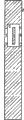
Now with the schematic view illustrating of Fig. 1 Ventilating door structure of the present utility model.
In Fig. 1, the 1st, the outside air-vent of existing Ventilating door, the 2nd, Ventilating door body [or claiming door leaf] is loaded on the door-hinge.The 3rd, shading piece is a slice shading baffle plate at this, the 4th, and the indoor air-vent of existing Ventilating door, the 5th, the gas-permeable channels of Ventilating door body junction chamber outside air-vent 1 and indoor air-vent 4.
Outside air-vent 1 is opened on the outer panels of door leaf 2, can form by one group of long and narrow stamping forming pore, also can form by one group of railing or blade, with the position of indoor air-vent 4 is relative, outer side of door one end of gas-permeable channels 5 is to lead to outside air-vent 1, the inboard end of door of gas-permeable channels 5 is to lead to indoor air-vent 4, indoor air-vent 4 is opened on the wainscot of door leaf 2, in the gas-permeable channels 5 of the position of shading piece 3 between outside air-vent 1 and indoor air-vent 4, if there is not shading piece 3, on Ventilating door indoor air-vent 4, load onto wicket again, the aforementioned exactly common exterior door that has door in door, obviously at this moment outdoor people can be through outside air-vent 1, gas-permeable channels 5, indoor air-vent 4 is seen indoor.After having added shading piece 3 in the gas-permeable channels 5, the light path from outdoor to indoor is blocked, and promptly outdoor people's sight line is stopped that by it outdoor people can not see indoor, and air also can normally circulate, and this has just realized the purpose of this utility model.
Below in conjunction with Fig. 2 the utility model is further specified.In Fig. 2, the 1st, an outside air-vent of Ventilating door, outside air-vent 1 is opened on the outer panels of door leaf 2, can form by one group of long and narrow stamping forming pore, also can form by one group of railing or blade, the 2nd, the Ventilating door body, the 3rd, shading piece, being two shading baffle plates, also can be two reinforcing ribs or stiffening girder, can also be the occulter that is bent into by steel plate, the 4th, two indoor air-vents of existing Ventilating door, open on the wainscot of door leaf 2, the 5th, the gas-permeable channels of existing Ventilating door junction chamber outside air-vent 1 and indoor air-vent 4, the position of shading piece 3 is in two sides of outside air-vent 1.The position of outside air-vent 1 is the middle part at outer side of door, the position of indoor air-vent 4 is the upper and lowers in the indoor, outer side of door one end of gas-permeable channels 5 is to lead to outside air-vent 1, the inboard end of door of gas-permeable channels 5 is to lead to indoor air-vent 4, when not being enough far away in the position of outside air-vent 1 and indoor air-vent 4, outdoor people also can see indoor through outside air-vent 1, gas-permeable channels 5, indoor air-vent 4.After having added shading piece 3, the light path from outdoor to indoor is blocked, and outdoor people's sight line is stopped by it, and air also can normally circulate, and this has also realized the purpose of this utility model.
Below in conjunction with embodiment the utility model is described.
[four] description of drawings: Fig. 1 is the structural representation of Ventilating door, and Fig. 2 is further specifying the utility model structure.Fig. 3 is the embodiment that there is the outdoor Ventilating door of a door in door indoor.Fig. 4 is the embodiment that there is the outdoor Ventilating door of 2 door in door the indoor.Fig. 5 also is the embodiment that there is the outdoor Ventilating door of 2 door in door the indoor.Fig. 6 is the embodiment that there is the outdoor Ventilating door of 3 door in door the indoor.
[five] specific embodiment:
Below in conjunction with embodiment the Ventilating door structure that shading piece is arranged is described.
The schematic diagram of the 1st visible Fig. 1 of embodiment of the present utility model, the schematic diagram of 2 visible Fig. 2 Ventilating doors of embodiment of the mat woven of fine bamboo strips of the present utility model, their structures were explained in preceding the sixth of the twelve Earthly Branches, and these two kinds of Ventilating doors can be used for places such as bathroom door.
The 3rd embodiment of the present utility model is the outdoor Ventilating door that there is a door in door indoor, and its structural representation is seen Fig. 3, and Fig. 3 is the practical application of the schematic diagram of Fig. 1 Ventilating door.In Fig. 3, the 1st, the outside air-vent of Ventilating door, open on the outer panels of door leaf 2, can form by one group of long and narrow pore or railing or blade, the 2nd, Ventilating door body, the 3rd, shading piece, at this is a slice shading baffle plate, the 4th, door in door, a wicket that is loaded on the air-vent of Ventilating door indoor just, the 5th, the gas-permeable channels of Ventilating door junction chamber outside air-vent 1 and indoor air-vent 4.The state of Fig. 3 is the door in door closing state, and this moment, door was airtight.When needs are ventilative, wicket 4 is opened, the air of indoor and outdoor via 1,5 and the wicket 4 opened can realize exchange.Owing to added shading piece 3, the light path from outdoor to indoor is blocked, and outdoor people's sight line is stopped by it, has also protected individual privacy in ventilative.
The 4th embodiment of the present utility model is that the indoor has the outdoor Ventilating door of two door in door up and down, and its structural representation is seen Fig. 4, and Fig. 4 also is the practical application of Fig. 2 Ventilating door schematic diagram.In Fig. 4, the 1st, the outside air-vent of Ventilating door, open on the outer panels of door leaf 2, can form by 2 groups of long and narrow pores or railing or blade, the 2nd, the Ventilating door body, the 3rd, shading piece, being two shading baffle plates or two reinforcing ribs or stiffening girder, can also be the occulter that is bent into by steel plate, the 4th, and door in door, a wicket that is loaded on the air-vent of Ventilating door indoor just, the 5th, the gas-permeable channels of Ventilating door junction chamber outside air-vent 1 and indoor air-vent 4.The state of Fig. 4 is the door in door closing state, and this moment, door was airtight.When needs are ventilative, wicket 4 is opened, the air of indoor and outdoor via 1,5 and the wicket 4 opened can realize exchange.Owing to added shading piece 3, the light path from outdoor to indoor is blocked, and outdoor people's sight line is stopped by it, has also protected individual privacy in ventilative.
The 5th embodiment of the present utility model also is that the indoor has the outdoor Ventilating door of two door in door up and down, and its structural representation is seen Fig. 5, and Fig. 5 also is the practical application of Fig. 2 Ventilating door schematic diagram.Fig. 5 is very similar with Fig. 4, and the position that its difference is its shading piece 3 has moved on to the bottom of top door in door and the top of bottom door in door by the both sides of the outside air-vent 1 of Ventilating door.In Fig. 5, the 1st, the outside air-vent of Ventilating door, the 2nd, the Ventilating door body, the 3rd, shading piece, being two shading baffle plates or two reinforcing ribs or stiffening girder, can also be the occulter that is bent into by steel plate, the 4th, and door in door, also be the wicket that is loaded on the air-vent of Ventilating door indoor, the 5th, the gas-permeable channels of Ventilating door junction chamber outside air-vent 1 and indoor air-vent 4.The state of Fig. 5 is the door in door closing state, and this moment, door was airtight.When needs are ventilative, wicket 4 is opened, the air of indoor and outdoor via 1,5 and the wicket 4 opened can realize exchange.Owing to added shading piece 3, the light path from outdoor to indoor is blocked, and outdoor people's sight line is stopped by it, has also protected individual privacy in ventilative.
The 6th embodiment of the present utility model is that the outside has three air-vents of upper, middle and lower, there is the outdoor Ventilating door of two door in door up and down the indoor, its structural representation is seen Fig. 6, in Fig. 6, the 1st, the outside air-vent of Ventilating door, the 2nd, the Ventilating door body, the 3rd, shading piece, be 4 shading baffle plates or reinforcing rib, stiffening girder, it can also be the occulter that is bent into by steel plate, the 4th, door in door also is the wicket that is loaded on the air-vent of Ventilating door indoor, the 5th, and the gas-permeable channels of Ventilating door junction chamber outside air-vent 1 and indoor air-vent 4.The state of Fig. 6 is the door in door closing state, and this moment, door was airtight.When needs are ventilative, wicket 4 is opened, the air of indoor and outdoor via 1,5 and the wicket 4 opened can realize exchange.Owing to added shading piece 3, the light path from outdoor to indoor is blocked, and outdoor people's sight line is stopped by it, has also protected individual privacy in ventilative.
Claims (5)
1. one kind by Ventilating door body (2), the outside air-vent (1) of Ventilating door, and indoor air-vent (4), the Ventilating door that gas-permeable channels parts such as (5) constitute is characterized in that: also have shading piece (3) in gas-permeable channels (5).
2. by the described Ventilating door of claim 1, it is characterized in that: outer side of door one end of gas-permeable channels (5) is to lead to outside air-vent (1), the inboard end of door of gas-permeable channels (5) is to lead to indoor air-vent (4), and shading piece (3) is to be in the position of in the gas-permeable channels (5) light path between indoor and outdoor being blocked.
3. by claim 1 or 2 described Ventilating doors, it is characterized in that: its shading piece (3) can be reinforcing rib or stiffening girder, also can be the shading baffle plate, can also be the occulter that is bent into by steel plate.
4. by claim 1 or 2 described Ventilating doors, it is characterized in that: its outside air-vent (1) is opened on the outside steel plate of Ventilating door body (2), plank, can be made up of one group of long and narrow stamping forming air flue, also can be made up of one group of railing or blade.
5. by claim 1 or 2 described Ventilating doors, it is characterized in that: on its indoor air-vent (4) wicket that is commonly called as to door in door can be housed.
Priority Applications (1)
| Application Number | Priority Date | Filing Date | Title |
|---|---|---|---|
| CN2010201811453U CN201730497U (en) | 2010-04-12 | 2010-04-12 | Ventilation door |
Applications Claiming Priority (1)
| Application Number | Priority Date | Filing Date | Title |
|---|---|---|---|
| CN2010201811453U CN201730497U (en) | 2010-04-12 | 2010-04-12 | Ventilation door |
Publications (1)
| Publication Number | Publication Date |
|---|---|
| CN201730497U true CN201730497U (en) | 2011-02-02 |
Family
ID=43521653
Family Applications (1)
| Application Number | Title | Priority Date | Filing Date |
|---|---|---|---|
| CN2010201811453U Expired - Fee Related CN201730497U (en) | 2010-04-12 | 2010-04-12 | Ventilation door |
Country Status (1)
| Country | Link |
|---|---|
| CN (1) | CN201730497U (en) |
Cited By (5)
| Publication number | Priority date | Publication date | Assignee | Title |
|---|---|---|---|---|
| CN102213060A (en) * | 2010-04-12 | 2011-10-12 | 陶小京 | Ventilative door |
| CN102787793A (en) * | 2011-05-14 | 2012-11-21 | 陶小京 | Ventilating door |
| US11906506B1 (en) * | 2021-12-21 | 2024-02-20 | Omidreza Ghanadiof | System and method for inspecting and maintaining the exterior elevated elements of building structures |
| US12033314B2 (en) | 2021-12-21 | 2024-07-09 | Omidreza Ghanadiof | System and method for inspecting and maintaining the exterior elevated elements of building structures |
| US12318912B2 (en) | 2021-12-21 | 2025-06-03 | Omidreza Ghanadiof | System and method for inspecting and maintaining the exterior elevated elements of building structures |
-
2010
- 2010-04-12 CN CN2010201811453U patent/CN201730497U/en not_active Expired - Fee Related
Cited By (5)
| Publication number | Priority date | Publication date | Assignee | Title |
|---|---|---|---|---|
| CN102213060A (en) * | 2010-04-12 | 2011-10-12 | 陶小京 | Ventilative door |
| CN102787793A (en) * | 2011-05-14 | 2012-11-21 | 陶小京 | Ventilating door |
| US11906506B1 (en) * | 2021-12-21 | 2024-02-20 | Omidreza Ghanadiof | System and method for inspecting and maintaining the exterior elevated elements of building structures |
| US12033314B2 (en) | 2021-12-21 | 2024-07-09 | Omidreza Ghanadiof | System and method for inspecting and maintaining the exterior elevated elements of building structures |
| US12318912B2 (en) | 2021-12-21 | 2025-06-03 | Omidreza Ghanadiof | System and method for inspecting and maintaining the exterior elevated elements of building structures |
Similar Documents
| Publication | Publication Date | Title |
|---|---|---|
| CN201817940U (en) | Internal recycling double-layer curtain wall | |
| CN201730497U (en) | Ventilation door | |
| CN203308349U (en) | Ventilating window with air filtering mullion | |
| CN104060733A (en) | Photovohaic curtain wall | |
| CN201068611Y (en) | Unit type external ventilation double-layer curtain wall | |
| CN205677115U (en) | A kind of building curtain wall ventilation unit | |
| CN101787843A (en) | Sound-proof and dedusting ventilate device | |
| CN203905758U (en) | Ventilation sound-insulation window | |
| CN104653049A (en) | Ventilation door | |
| WO2009084878A3 (en) | Double window having horizontal cross-ventilation function | |
| CN201205479Y (en) | Plate type air noise reduction, dust removal filter and noise reduction, dust removal ventilation window | |
| CN203240703U (en) | Glass curtain wall interlayer ventilation system for building | |
| CN204850183U (en) | Novel curtain ventilation structure | |
| CN2775171Y (en) | Internal circulation double layer curtain wall | |
| CN102213060A (en) | Ventilative door | |
| CN202500245U (en) | A double-layer curtain wall with hidden frame and narrow cavity | |
| CN201546597U (en) | Fixed type aluminum extruded rainproof shutter | |
| CN201874409U (en) | Ventilating door | |
| JP3143015U (en) | Duct integrated ventilation louver | |
| CN101016822A (en) | Environmental protection energy-saving ventilating noise reduction window | |
| CN205046726U (en) | Curtain is breathed to developments | |
| CN210267545U (en) | A kind of external air purification box for building | |
| CN204534954U (en) | Window ventilation purifier | |
| CN102787793A (en) | Ventilating door | |
| CN202882705U (en) | Ventilating door |
Legal Events
| Date | Code | Title | Description |
|---|---|---|---|
| C14 | Grant of patent or utility model | ||
| GR01 | Patent grant | ||
| C17 | Cessation of patent right | ||
| CF01 | Termination of patent right due to non-payment of annual fee |
Granted publication date: 20110202 Termination date: 20130412 |