Children trolley
Technical field
The utility model relates to a kind of children trolley.
Background technology
Children trolley of the prior art, comprise the go-cart vehicle frame, be arranged at described go-cart vehicle frame rear lower wheel assembly, be arranged at the preceding bottom of described go-cart vehicle frame front component, be arranged at the seat mechanism on the described go-cart vehicle frame, described seat mechanism comprises seat frame, is arranged at the seat pocket of sitting or lying for children on the described seat frame, usually seat frame removably is connected with described go-cart vehicle frame, when seat mechanism need commutate, need to install after seat frame turns under the dismounting, operation is trouble again.
The utility model content
The technical problems to be solved in the utility model provides a kind of children trolley.
In order to solve the problems of the technologies described above, the technical solution adopted in the utility model is: a kind of children trolley, comprise the go-cart vehicle frame, be arranged at the wheel assembly of described go-cart vehicle frame rear lower, be arranged at the front component of the preceding bottom of described go-cart vehicle frame, be arranged at the seat mechanism on the described go-cart vehicle frame, described seat mechanism comprises seat frame, be arranged at the seat pocket of sitting or lying for children on the described seat frame, described seat frame is provided with first rotating shaft, described seat frame can be arranged on the described go-cart vehicle frame rotationally around described first rotating shaft, be provided with between described seat frame and the described go-cart vehicle frame and be used to lock the lockout mechanism of position between the two, described seat frame has forward condition and reverse state, when described seat frame is under the forward condition, the top of described seat frame is positioned at the rear side of vertical guide at the place, axle center of described first rotating shaft, when described seat frame is under the reverse state, the top of described seat frame is positioned at the front side of vertical guide at the place, axle center of described first rotating shaft.
In some embodiments, be rotatably connected to Connection Block by described first rotating shaft on the described seat frame, described Connection Block can connect mutually with described go-cart vehicle frame with dismantling.
In some embodiments, described seat pocket is the seat pocket that is arranged at the cloth material on the described seat frame, described seat pocket has first side and second side, when described seat frame is under the forward condition, described first side is the medial surface of described seat pocket, when described seat frame is under the reverse state, described seat frame is under the reverse state, and second side of described seat pocket is the medial surface of described seat pocket.When seat frame goes to from forward condition under the direction state, the seat pocket only needs first side is pulled outwardly as lateral surface, and inwardly draw as medial surface former second side that is used as lateral surface, need not the seat pocket is pulled down, and operates simpler.
In some embodiments, described seat frame is provided with awning, described awning comprises bracing frame, be arranged on the shutter body on the described bracing frame, described bracing frame and described seat frame are provided with rotatedly, described shutter body comprises the 3rd side and the 4th side, when described seat frame is under the forward condition, described shutter body forms on the top of described seat frame and blocks the space, and described the 3rd side is facing to described seat pocket, when described seat frame is under the reverse state, described shutter body forms on the top of described seat frame and blocks the space, and described the 4th side is facing to described seat pocket.When the mode of operation of seat frame changed, the mode of operation of awning can be followed correspondingly and change.
In some embodiments, can be provided with awning on the described seat frame, described awning comprises described bracing frame, is arranged on the described shutter body on the described bracing frame with dismantling.The mode of operation that changes awning needs the awning dismounting is adjusted down.
The bottom pivotal joint of described seat frame has the step frame, is provided with the step lockout mechanism between described step frame and the described seat frame.
Scope of the present utility model is not limited to the technical scheme that the particular combinations of above-mentioned technical characterictic forms, and also should contain simultaneously by above-mentioned technical characterictic or its equivalent feature to carry out combination in any and other technical scheme of forming.The technical characterictic that disclosed (but being not limited to) has a similar functions among for example above-mentioned feature and the application is replaced mutually and technical scheme of forming etc.
Because technique scheme utilization, the utility model compared with prior art has following advantage: the utility model provides the design plan of another kind of technical conceive, when changing the seat frame mode of operation, only needs the lockout mechanism release, and behind the rotation seat frame again the locking get final product, operate simpler.
Description of drawings
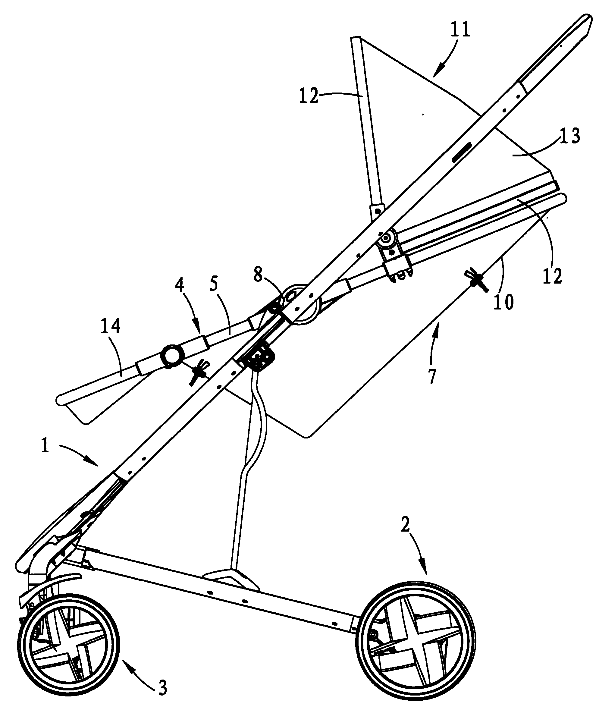
Accompanying drawing 1 is front view one of the present utility model (seat frame is in forward condition);
Accompanying drawing 2 is front view two of the present utility model (seat frame is in forward condition);
Accompanying drawing 3 is front view three of the present utility model (seat frame is in forward condition);
Accompanying drawing 4 is front view four of the present utility model (seat frame is in reverse state);
Accompanying drawing 5 is front view five of the present utility model (seat frame is in reverse state);
Accompanying drawing 6 is front view six of the present utility model (seat frame is in reverse state);
Accompanying drawing 7 is the block diagram of seat mechanism;
Accompanying drawing 8 is the front view of seat mechanism.
Wherein: 1, go-cart vehicle frame; 2, wheel assembly; 3, front component; 4, seat mechanism; 5, seat frame; 6, first rotating shaft; 7, seat pocket; 8, Connection Block; 9, first side; 10, second side; 11, awning; 12, bracing frame; 13, shutter body; 14, step frame.
The specific embodiment
Shown in accompanying drawing 1-accompanying drawing 6, a kind of children trolley, comprise go-cart vehicle frame 1, be arranged at described go-cart vehicle frame 1 rear lower wheel assembly 2, be arranged at described go-cart vehicle frame 1 preceding bottom front component 3, be arranged at the seat mechanism 4 on the described go-cart vehicle frame 1.
Shown in each accompanying drawing, described seat mechanism 4 comprises seat frame 5, is arranged at the seat pocket 7 of sitting or lying for children on the described seat frame 5.As shown in Figure 7, described seat frame 5 is provided with first rotating shaft 6, described seat frame 5 can be arranged on the described go-cart vehicle frame 1 rotationally around described first rotating shaft 6, described seat frame 5 can be directly to be connected rotatedly with described go-cart vehicle frame 1 by described first rotating shaft 6, and seat mechanism 4 just cannot remove on described go-cart vehicle frame 1; Described seat frame 5 also can be to be rotatably connected to Connection Block 8 by described first rotating shaft 6, described Connection Block 8 can connect mutually with described go-cart vehicle frame 1 with dismantling, makes described seat mechanism 4 just can remove from described go-cart vehicle frame 1 by this Connection Block 8.
Be provided with between described seat frame 5 and the described go-cart vehicle frame 1 and be used to lock the lockout mechanism of position between the two, lockout mechanism is not invention main points of the present utility model, and the lockout mechanism that everything locks between can the parts with two rotation relations can both use at this.Such as being to offer first teeth groove on the seat frame 5, offer second teeth groove on the described Connection Block 8, slide between first teeth groove and described second teeth groove and be provided with the slip teeth piece, during locking, the slip teeth piece is inserted in described first teeth groove and described second teeth groove simultaneously, during release, the slip teeth piece only is inserted in first teeth groove or only is inserted in second teeth groove.And for example slide on seat frame 5 and be provided with locating dowel pin, and have a plurality of lockholes on Connection Block 8, the axle center that each described lockhole all is positioned at described first rotating shaft 6 is on the circumferencial direction in the center of circle.
Described seat frame 5 has forward condition and reverse state, shown in accompanying drawing 1-accompanying drawing 3, when described seat frame 5 is under the forward condition, the top of described seat frame 5 is positioned at the rear side of vertical guide at the place, axle center of described first rotating shaft 6, the top of described seat frame 5 promptly is meant after children are sitting in the seat mechanism 4, and is corresponding that part of with children's head; Shown in accompanying drawing 4-accompanying drawing 6, when described seat frame 5 is under the reverse state, the top of described seat frame 5 is positioned at the front side of vertical guide at the place, axle center of described first rotating shaft 6.Shown in accompanying drawing 1-accompanying drawing 6, described seat frame 5 is under the forward condition or under the reverse state, lockout mechanism can be locked at least two positions with described seat frame 5, shown in accompanying drawing 1-accompanying drawing 6, described seat frame 5 is under the forward condition or under the reverse state, lockout mechanism can both be locked in three positions with described seat frame 5.
Described seat pocket 7 is for being arranged at the seat pocket 7 of the cloth material on the described seat frame 5, described seat pocket 7 has first side 9 and second side 10, when described seat frame 5 is under the forward condition, described first side 9 is the medial surface of described seat pocket 7, and second side 10 is lateral surface; When described seat frame 5 is under the reverse state, second side 10 of described seat pocket 7 be the medial surface of described seat pocket 7, and described first side 9 is the lateral surface of described pocket 7.Promptly when described seat frame 5 after the conversion of forward condition and reverse state, need with the cloth material the seat pocket 7 turn over.
Described seat frame 5 is provided with awning 11.The setting of described awning has following two kinds of forms:
One, can be provided with awning 11 on the described seat frame 5, described awning 11 comprises described bracing frame 12, is arranged on the shutter body 13 on the described bracing frame 12 with dismantling.When described seat frame 5 by forward condition after reverse state conversion, awning 11 just is positioned at the below of seat frame 5, at this moment, just awning 11 can be pulled down on seat frame 5, then with awning 11 upsets and be installed on the top on the top of described seat frame 5.
Two, described awning 11 comprises bracing frame 12, be arranged on the shutter body 13 on the described bracing frame 12, described bracing frame 12 is provided with rotatedly with described seat frame 5, described shutter body 13 comprises the 3rd side and the 4th side, when described seat frame 5 is under the forward condition, described shutter body 13 forms on the top of described seat frame 5 and blocks the space, and described the 3rd side is facing to described seat pocket 7, when described seat frame 5 is under the reverse state, described shutter body 13 forms on the top of described seat frame 5 and blocks the space, and described the 4th side is facing to described seat pocket 7.When described seat frame 5 by forward condition after reverse state conversion, awning 11 just is positioned at the below of seat frame 5, at this moment, described bracing frame 12 upwards can be rotated, and go to the top on the top of described seat frame 5, thereby spur the top that described shutter body 13 also is pulled to the top of described seat frame 5.
The bottom pivotal joint of described seat frame 5 has step frame 14, is provided with the step lockout mechanism between described step frame 14 and the described seat frame 5.Similarly, the step lockout mechanism is not invention main points of the present utility model, every two lockout mechanisms that lock between the parts in relative rotation can both can uses at this.
And the form of step is not limit, can be that plastics are made, can be metal toe board, for consistent with the seat pocket 7 in the present embodiment, what adopt in the present embodiment is the step that step frame 14 is provided with the cloth material, and also can equally overturn by the entablement pocket.
The foregoing description only is explanation technical conceive of the present utility model and characteristics, and its purpose is to allow the personage who is familiar with this technology can understand content of the present utility model and enforcement according to this, can not limit protection domain of the present utility model with this.All equivalences of being done according to the utility model spirit change or modify, and all should be encompassed within the protection domain of the present utility model.